EP0527103A2 - System für die grafische Darstellung von auf Drehbänken bearbeiteten Werkstücken - Google Patents
System für die grafische Darstellung von auf Drehbänken bearbeiteten Werkstücken Download PDFInfo
- Publication number
- EP0527103A2 EP0527103A2 EP92500102A EP92500102A EP0527103A2 EP 0527103 A2 EP0527103 A2 EP 0527103A2 EP 92500102 A EP92500102 A EP 92500102A EP 92500102 A EP92500102 A EP 92500102A EP 0527103 A2 EP0527103 A2 EP 0527103A2
- Authority
- EP
- European Patent Office
- Prior art keywords
- points
- profile
- display
- point
- tool
- Prior art date
- Legal status (The legal status is an assumption and is not a legal conclusion. Google has not performed a legal analysis and makes no representation as to the accuracy of the status listed.)
- Withdrawn
Links
Images


Classifications
-
- G—PHYSICS
- G05—CONTROLLING; REGULATING
- G05B—CONTROL OR REGULATING SYSTEMS IN GENERAL; FUNCTIONAL ELEMENTS OF SUCH SYSTEMS; MONITORING OR TESTING ARRANGEMENTS FOR SUCH SYSTEMS OR ELEMENTS
- G05B19/00—Program-control systems
- G05B19/02—Program-control systems electric
- G05B19/18—Numerical control [NC], i.e. automatically operating machines, in particular machine tools, e.g. in a manufacturing environment, so as to execute positioning, movement or co-ordinated operations by means of program data in numerical form
- G05B19/406—Numerical control [NC], i.e. automatically operating machines, in particular machine tools, e.g. in a manufacturing environment, so as to execute positioning, movement or co-ordinated operations by means of program data in numerical form characterised by monitoring or safety
- G05B19/4069—Simulating machining process on screen
-
- Y—GENERAL TAGGING OF NEW TECHNOLOGICAL DEVELOPMENTS; GENERAL TAGGING OF CROSS-SECTIONAL TECHNOLOGIES SPANNING OVER SEVERAL SECTIONS OF THE IPC; TECHNICAL SUBJECTS COVERED BY FORMER USPC CROSS-REFERENCE ART COLLECTIONS [XRACs] AND DIGESTS
- Y02—TECHNOLOGIES OR APPLICATIONS FOR MITIGATION OR ADAPTATION AGAINST CLIMATE CHANGE
- Y02P—CLIMATE CHANGE MITIGATION TECHNOLOGIES IN THE PRODUCTION OR PROCESSING OF GOODS
- Y02P90/00—Enabling technologies with a potential contribution to greenhouse gas [GHG] emissions mitigation
- Y02P90/02—Total factory control, e.g. smart factories, flexible manufacturing systems [FMS] or integrated manufacturing systems [IMS]
Definitions
- the object of the patent is a system for the graphic display of parts machined by machine tools with a rotating drive, such as a lathe.
- the novelty of the system lies in the provision of real information of the contour of the machined part to allow the display of asymmetric forms, namely a threading. It also allows the visual display of an unwanted threading due to an excessive forward speed of the tool and also a slight roughness indicating the quality of the surface finish.
- the system is independent of the graphic display used, is applicable to both line graphics and solid graphics and can be incorporated not only to numerical controls governing machine-tools of the said kind but conveniently to computer aided design (CAD) systems to detect possible errors in the machine-tool's control programs, prior to machining as such, which would lead to machining faults, such as the said unwanted threadings or the deficient quality of the surface finish of the machined part.
- CAD computer aided design
- Both display systems fulfil the basic function of providing graphics simulating the changing form of a working part that is to be or is being machined.
- the use thereof has a number of drawbacks when the working part is being machined for the formation of say a thread, inasmuch as the thread profiles are shown as a straight line or at best are replaced by predefined cog-like sectors symbolising the threading, but containing no real information on the execution thereof.
- Another drawback of these diplay systems, perchance graver than the above, is that one cannot distinguish when the poor programming of the forward speed of the tool cutter causes the profile of the machined part to resemble a threading, when such was not expected.
- the object of this invention is to overcome the drawbacks of the above systems.
- a template is established of the working part to be displayed on a plane containing the main spin axis of the said part, which allows two profiles or contours to be defined, an upper and a lower one.
- the system comprises taking samples of the position of the tool over a given time interval to obtain sampling points containing information of not only the spatial position but also the angular position thereof about the main spin axis of the machine. Once the sampling points are known, the system calculates the coordinates of the points corresponding to the two profiles to be displayed and relative to the measurement interval.
- the modifications to the profiles due to the machining process are displayed by clearing the area in which the working part template and the machining tool template interfere, which contains real information on the specific form of each machine used in the machining process.
- the interference areas between both templates are determined for each point representing the profiles and not by scanning between both consecutive points, so that the said areas have the real form of the "biting" of the tool.
- the display on screen of the interference areas discretely and not by scanning allows an easy detection of when an excessive forward speed of the tool has been programmed, for if the said tool moves forward very quickly, unremoved material areas shall appear between both profile points, clearly visible on screen as an uneven profile corresponding to an unwanted thread form.
- information can be obtained as to the roughness of the surface finish of each step of the machining process, which shall depend both upon the size and shape of the tool and the speed of the various axes.
- the system of the invention uses the profile interpolation technique.
- This technique is generic and valid for any kind of graphic display of a system with a main spin axis, such as a lathe.
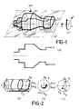
- Figure 1 shows the basic idea of the technique which comprises drawing two profiles on the display screen, an upper (A) and a lower (B) screen, figure 1b, obtained by means of a longitudinal section in a plane containing the main spin axis of the part to machine (MP), figure 1.
- MP part to machine
- the display system takes a sample of points P m1 , P m2 , ... P mn , relative to the position of the tip of the machining tool, as illustrated in figures 2 a and b. From the known sequence of such points, points P a and P b respectively for the upper profile (A) and lower profile (B) points are calculated. This calculation is carried out by means of a simple interpolation process. For instance, and with regard to figure 2c, the intermediate point P b is obtained from points P1 of coordinates (x1, z1, s1) and P2 of coordinates (x2, z2, s2) using:
- step (9) of the system executes a sampling of an initial point P1 of coordinates (x1, z1, s1).
- the angular coordinate s1 of this point P1 is then compared at step (10) to determine whether its value is above or below 180° and continue the procedure at point (C) of figure 3b or at point (D) of figure 3c, as appropriate.
- step numbered (11) in figure 3b involves taking the sampling at the position P2 (x2, z2, s2) at which the tip of the tool used in machining is located, thereafter, at step (12) to determine whether its angular position coordinate, s2, is above the value of 180°. Otherwise the process returns to step (11) executing the sampling at a new point.
- the process applies the profile interpolation technique using P1 determined at step (10) as the starting point and P2 as the end point, determining by means of equations (1) the spatial coordinates, x b , z b for the first point of the new lower profile (B).
- the new starting point from which the profile interpolation shall continue to be applied shall be the end sampling point P2.
- the "bite" is drawn on screen. If the graphic display system is a line system, the profile and tool templates are superposed, figure 4a, replacing the profile sector of the part comprised between the points of intersection of both profiles with the relevant profile sector of the tool, as shown in figure 4b. If the graphic display system is a solid system, the common area of both solids simulating the part and the tool is deemed as “consumed” and the screen points contained in such area are cleared to obtain as a result the profile change shown in figures 5a and b.
- the procedure continues at point (D) of figure 3c with a new sampling step (11) described above to obtain a new point P2 and determine whether the angular position coordinate thereof has in this case exceeded the value of 360° step (16), determining at step (17) the spatial coordinates x a , z a at a point P a , this time for the new upper profile (A), and taking point P2 as the new starting point.
- step (18) similarly to step (14), the profile is updated, in this case the upper profile (A) and the whole procedure is repeated from step (11) point (C) in figure 3b as many times as necessary, obtaining new points that in all make up the true, and not necessarily symmetrical, profile of the machined part.
- FIGS. 6 a-c show the result obtained using the subject system.
- Figures 6b and 6c show the form of the profile viewed on the display, at successive machining stages, using different kinds of cutters (MC, MC′). Such profiles clearly show the crests of unremoved material due to an excessive forward speed of the cutter.
- Figure 6a shows the profile that would be obtained applying a procedure as described in the art.
- This system for the graphic display of lathe machined work can be incorporated to the machine's numerical control.
- Another convenient use is its application in computer aided design (CAD) systems, allowing the detection, even at a simulation stage prior to machining, of possible errors in the data of the machine-tool control programs regarding forward speed of the various axes, which errors would lead to faults in the machining finish or breaking of the cutter used.
- CAD computer aided design
Landscapes
- Engineering & Computer Science (AREA)
- Human Computer Interaction (AREA)
- Manufacturing & Machinery (AREA)
- Physics & Mathematics (AREA)
- General Physics & Mathematics (AREA)
- Automation & Control Theory (AREA)
- Numerical Control (AREA)
Applications Claiming Priority (2)
| Application Number | Priority Date | Filing Date | Title |
|---|---|---|---|
| ES09101839A ES2081729B1 (es) | 1991-08-06 | 1991-08-06 | Sistema para la representacion grafica de mecanizados de torno. |
| ES9101839 | 1991-08-06 |
Publications (2)
| Publication Number | Publication Date |
|---|---|
| EP0527103A2 true EP0527103A2 (de) | 1993-02-10 |
| EP0527103A3 EP0527103A3 (en) | 1993-11-03 |
Family
ID=8273249
Family Applications (1)
| Application Number | Title | Priority Date | Filing Date |
|---|---|---|---|
| EP19920500102 Withdrawn EP0527103A3 (en) | 1991-08-06 | 1992-08-03 | System for the graphic display of lathe machined work |
Country Status (2)
| Country | Link |
|---|---|
| EP (1) | EP0527103A3 (de) |
| ES (1) | ES2081729B1 (de) |
Cited By (2)
| Publication number | Priority date | Publication date | Assignee | Title |
|---|---|---|---|---|
| CN104607672A (zh) * | 2015-02-03 | 2015-05-13 | 山东信和造纸工程股份有限公司 | 一种用于机械加工过程中的观察系统及其使用方法 |
| CN103886120B (zh) * | 2012-12-21 | 2017-08-11 | 中国直升机设计研究所 | 一种大型产品数字样机轻量可视化方法 |
Family Cites Families (9)
| Publication number | Priority date | Publication date | Assignee | Title |
|---|---|---|---|---|
| DE1258636B (de) * | 1965-07-31 | 1968-01-11 | Vyzk Ustav Mat Strojuu | Vorrichtung zur Pruefung eines Programms, insbesondere fuer die numerische Steuerung von Werkzeugmaschinen |
| JPS58177251A (ja) * | 1982-04-07 | 1983-10-17 | Yamazaki Mazak Corp | 図形表示機能をもつ数値制御装置における加工仕上形状表示方法 |
| JPS59216208A (ja) * | 1983-05-23 | 1984-12-06 | Mitsubishi Electric Corp | 数値制御装置 |
| JPS60209810A (ja) * | 1984-04-02 | 1985-10-22 | Mitsubishi Electric Corp | 数値制御装置 |
| JP2685071B2 (ja) * | 1986-03-10 | 1997-12-03 | 三菱電機株式会社 | 数値制御装置 |
| DE3616740A1 (de) * | 1986-05-17 | 1987-11-19 | Heidenhain Gmbh Dr Johannes | Vorrichtung zur gewinnung von werkstueckkonturen |
| ES2000136A6 (es) * | 1986-08-08 | 1987-12-16 | Hernando Padellan David | Sistema de fabricacion para maquina-herramienta por copia de cotas del modelo |
| JPH02252004A (ja) * | 1989-03-24 | 1990-10-09 | Fanuc Ltd | 工具形状描画方式 |
| IT1232128B (it) * | 1989-07-05 | 1992-01-23 | Advanced Data Processing | Dispositivo elettronico di interpolazione polinomiale per controlli numerici di macchine utensili, particolarmente fresatrici per la lavorazione di stampi e macchina incorporante detto dispositivo |
-
1991
- 1991-08-06 ES ES09101839A patent/ES2081729B1/es not_active Expired - Lifetime
-
1992
- 1992-08-03 EP EP19920500102 patent/EP0527103A3/en not_active Withdrawn
Cited By (3)
| Publication number | Priority date | Publication date | Assignee | Title |
|---|---|---|---|---|
| CN103886120B (zh) * | 2012-12-21 | 2017-08-11 | 中国直升机设计研究所 | 一种大型产品数字样机轻量可视化方法 |
| CN104607672A (zh) * | 2015-02-03 | 2015-05-13 | 山东信和造纸工程股份有限公司 | 一种用于机械加工过程中的观察系统及其使用方法 |
| CN104607672B (zh) * | 2015-02-03 | 2017-02-01 | 山东信和造纸工程股份有限公司 | 一种用于机械加工过程中的观察系统及其使用方法 |
Also Published As
| Publication number | Publication date |
|---|---|
| ES2081729A1 (es) | 1996-03-01 |
| ES2081729B1 (es) | 1996-10-01 |
| EP0527103A3 (en) | 1993-11-03 |
Similar Documents
| Publication | Publication Date | Title |
|---|---|---|
| US4949270A (en) | Method of creating NC program for pocket machining | |
| EP0671677B1 (de) | Methode und Vorrichtung zur Feinbearbeitung von Werkstücken mit Hilfe numerischer Steuerung und computerunterstützter Simulationsfunktion | |
| AU713868B2 (en) | Tool grinding simulation system | |
| US5148372A (en) | Interactive graphic system for the mathematical representation of physical models | |
| US4757461A (en) | Process for graphically representing a structure | |
| US7062352B2 (en) | Method for displaying tool locus in NC data and method for analyzing NC data | |
| JP6516865B2 (ja) | 測定対象の寸法特性を決定するための方法及び装置 | |
| JP2578241B2 (ja) | 自動プログラム作成装置 | |
| WO2021044641A1 (ja) | Cadデータによるマシニングセンタの自動運転装置 | |
| EP0164686B1 (de) | Wechselwirkende numerische Steuerung für eine Werkzeugmaschine | |
| US7050925B2 (en) | Apparatus for integrated tool manufacture and method therefor | |
| JPH0962326A (ja) | Nc加工装置 | |
| US5099432A (en) | Method for determining machining process in numerical control information generating function | |
| JPH0565886B2 (de) | ||
| JP3378834B2 (ja) | 仕上げ加工方法および装置 | |
| JP2012018472A (ja) | 加工シミュレーション装置及び方法 | |
| DE19805155B4 (de) | Verfahren zum Erzeugen von Steuerdaten für Koordinatenmeßgeräte | |
| EP0527103A2 (de) | System für die grafische Darstellung von auf Drehbänken bearbeiteten Werkstücken | |
| JP2021072012A (ja) | 表示装置 | |
| EP1398683A2 (de) | System und Verfahren zur Erzeugung von numerisch gesteurten Werkzeugbahnen auf einem Festkörpermodell | |
| EP0113682A2 (de) | Numerisches Steuerungssystem und Verfahren | |
| DE102007044000A1 (de) | Verfahren zur Bestimmung einer Raumform eines Werkstücks | |
| JPH06170763A (ja) | 力制御を用いた研磨方法 | |
| DE19829661A1 (de) | Verfahren zur rechnergestützten Erzeugung von Steuerbefehlssequenzen für Roboter | |
| JPH0695293B2 (ja) | 数値制御装置における加工シミュレーション方法 |
Legal Events
| Date | Code | Title | Description |
|---|---|---|---|
| PUAI | Public reference made under article 153(3) epc to a published international application that has entered the european phase |
Free format text: ORIGINAL CODE: 0009012 |
|
| AK | Designated contracting states |
Kind code of ref document: A2 Designated state(s): CH DE FR IT LI |
|
| PUAL | Search report despatched |
Free format text: ORIGINAL CODE: 0009013 |
|
| RHK1 | Main classification (correction) |
Ipc: G05B 19/405 |
|
| AK | Designated contracting states |
Kind code of ref document: A3 Designated state(s): CH DE FR IT LI |
|
| 18D | Application deemed to be withdrawn |
Effective date: 19940504 |