EP0527204B1 - Am ausserende eines chirurgischen nagels zu befestigende vorrichtung - Google Patents
Am ausserende eines chirurgischen nagels zu befestigende vorrichtung Download PDFInfo
- Publication number
- EP0527204B1 EP0527204B1 EP91909781A EP91909781A EP0527204B1 EP 0527204 B1 EP0527204 B1 EP 0527204B1 EP 91909781 A EP91909781 A EP 91909781A EP 91909781 A EP91909781 A EP 91909781A EP 0527204 B1 EP0527204 B1 EP 0527204B1
- Authority
- EP
- European Patent Office
- Prior art keywords
- bore
- pin
- section
- securing
- cross
- Prior art date
- Legal status (The legal status is an assumption and is not a legal conclusion. Google has not performed a legal analysis and makes no representation as to the accuracy of the status listed.)
- Expired - Lifetime
Links
Images

Classifications
-
- A—HUMAN NECESSITIES
- A61—MEDICAL OR VETERINARY SCIENCE; HYGIENE
- A61B—DIAGNOSIS; SURGERY; IDENTIFICATION
- A61B17/00—Surgical instruments, devices or methods
- A61B17/56—Surgical instruments or methods for treatment of bones or joints; Devices specially adapted therefor
- A61B17/58—Surgical instruments or methods for treatment of bones or joints; Devices specially adapted therefor for osteosynthesis, e.g. bone plates, screws or setting implements
- A61B17/68—Internal fixation devices, including fasteners and spinal fixators, even if a part thereof projects from the skin
- A61B17/685—Elements to be fitted on the end of screws or wires, e.g. protective caps
Definitions
- the invention relates to a universal distal fixation element, in particular for the external protection of the end of a distal pin adaptable in particular to the finger of the hand but not exclusively for the latter.
- the distal pins commonly used in hand surgery for joint consolidation have diameters ranging from 0.8mm to 3mm, increasing from 0.2mm to 0.5mm.
- a distal fixing element in the form of a ball of plastic material resistant to passage through an autoclave. This ball is pierced from pole to pole with a hole allowing the passage of distal pins of neighboring diameters.
- a distal fixation member with a hole diameter of 1.2mm will accept pins of 0.8mm, 1.00mm, 1.2mm.
- the outside diameter of the ball will be larger.
- All these existing distal fixation elements are drilled in the plane of the equator by a tapped hole in which the screwing action of a screwdriver on a grub screw makes a point pressure on the pin inserted in the element , so that this element is thus immobilized in rotation and in translation on the spindle, thus preventing the latter from migrating in the hand, or in any other part of the body where this spindle could be installed.
- the distal fixation element facilitates by its aesthetic form the execution of the care and dressings, it thus avoids the surgeon from performing a 90 ° bending of the distal pin as was done before the creation of the distal fixation element .
- FR-A-2,633,822 To allow the use of a fixing element of this type for all the diameters of the existing pins, it has been proposed (FR-A-2,633,822) to provide the fixing element with two orthogonal bores at the intersection of which opens the threaded hole of the clamping screw.
- This known device is difficult to use for the surgeon who must choose the bore corresponding to the spindle that he has put in place.
- the unused bore constitutes a receptacle for organic products and organisms which are dangerous for the adjacent wound.
- the present invention aims to eliminate these drawbacks of the known fixing device according to FR-A-2,633,822, by means of a new device adapting without hesitation to all the diameters of the existing pins and which does not have an open bore after its implementation.
- the subject of the invention is a universal distal fixation element for surgical pins of all the diameters used, of the type comprising a protective sphere provided with a bore for a pin and a clamping screw housed in a tapped hole. which opens into said bore, characterized in that it comprises an elastically deformable insert by means of said clamping screw and coming into contact with at least one generator of the spindle to be protected, the deformable insert being in the form of a crescent whose length of the concave arc is approximately equal to the length of the circumference of the smallest allowable spindle, the radius before deformation corresponding to the radius of the largest allowable spindle diameter.
- the fixing element according to the invention thus allows a simple and safe adaptation to all spindle diameters, with a single bore for the different spindles.
- the elasticity of the insert causes it to return to the release position by loosening the screw.
- the two ends of the deformable crescent-shaped insert are superimposed in the region of action of the clamping screw.
- said bore has a cross section greater than that of the spindle of larger section, the through bore being formed by a bore portion with circular section of section corresponding to that of the spindle of larger diameter to which a portion is connected. a bore with a parallel axis whose section corresponds to that of the spindle of smaller diameter.
- Figure 1 is a schematic view in diametral section of a fixing device according to an exemplary embodiment of the invention
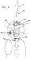
- Figure 2 is a schematic perspective view of a fixing device according to a variant of the invention
- Figure 3 is a diametrical sectional view at right angles to Figure 2
- Figure 4 is similar to Figure 3, for a variant
- FIG. 5 is analogous to FIG. 1, for another variant of the invention
- FIG. 6 is analogous to FIGS. 3 and 4, for the variant of FIG. 5.
- a single bore 20 of circular cross section corresponding to a diameter greater than the maximum admissible spindle diameter receives a deformable insert 19 which, under the action of the screw 28, will wrap the end of the pin to protect.
- This deformable insert 19, in the form of a crescent, can be obtained by spinning or extrusion.
- the length of the concave arc 23 of this crescent will be approximately equal to the length of the circumference of the smallest allowable spindle 21. Its radius 22 before deformation will correspond to the radius generated by the largest allowable spindle diameter in sphere 1.
- the sliding of the generators of the deformable insert 19 in the shape of a crescent along the generatrices of the hole 20 allows the enveloping of all the generatrices of the end of the distal pin to protect, thus involving a very large number of generators in immobilizing the sphere on the distal pin.
- a better centering of the spindle is ensured by making coincide a diameter 109 of the sphere 1 and the axis 110 of the spindle to be protected thanks to the sliding of the internal face starting at l the bevelled end of a ribbon 102 of constant thickness in the shape of a crescent, on the external face of the other beveled end of the same ribbon 102, in a housing 111 of the sphere 1.
- the spiral covering of the ribbon 102 that is to say the internal face 103 of the ribbon 102 against the external face 105, and the relative sliding of these two faces against each other are produced by the rotation of the screw 106 which , by driving the external face 105 of the ribbon 102, forces the latter to reduce the length of the original internal circumference.
- Clamping screw 106 has a thread whose pitch / diameter ratio is 8/100 unlike the thread of commonly used screws which is 6/100. The cessation of the tightening action of the screw allows, as in a spiral spring, the return of the ribbon to its original shape, thanks to the memory property of its material.
- the device allows clamping centered on pins 104 of small diameter as well as on pins 111 ′ of large diameter.
Landscapes
- Health & Medical Sciences (AREA)
- Orthopedic Medicine & Surgery (AREA)
- Surgery (AREA)
- Life Sciences & Earth Sciences (AREA)
- Heart & Thoracic Surgery (AREA)
- Nuclear Medicine, Radiotherapy & Molecular Imaging (AREA)
- Engineering & Computer Science (AREA)
- Biomedical Technology (AREA)
- Neurology (AREA)
- Medical Informatics (AREA)
- Molecular Biology (AREA)
- Animal Behavior & Ethology (AREA)
- General Health & Medical Sciences (AREA)
- Public Health (AREA)
- Veterinary Medicine (AREA)
- Surgical Instruments (AREA)
Claims (3)
- Am äußeren Ende von chirurgischen Nägeln in allen benutzten Durchmessern zu befestigendes Universalelement, bestehend aus einer Schutzkugel mit einer Bohrung für einen Nagel und einer Klemmschraube, die in einem in die genannte Bohrung einmündenden Gewindeloch angeordnet ist, dadurch gekennzeichnet, daß es einen Einsatz (17, 19, 102) umfaßt, der durch die Klemmschraube (28, 106) elastisch verformbar ist und der mit mindestens einer Erzeugenden des zu schützenden Nagels (14, 15, 101, 104) in Berührung kommt, wobei die Bohrung (2, 3) einen größeren Querschnitt als der Nagel mit dem größten Querschnitt (15, 111′) besitzt und wobei der verformbare Einsatz (19, 102) eine Sichelform aufweist, deren konkaver Bogen eine Länge hat, die annähernd gleich der Länge des Kreisumfangs des kleinsten zulässigen Nagels (21) ist, während der Radius vor der Verformung dem Radius des größten zulässigen Durchmessers des Nagels (23) entspricht.
- Befestigungselement nach Anspruch 1, dadurch gekennzeichnet, daß sich die Enden des verformbaren sichelförmigen Einsatzes (102) im Wirkungsbereich der Klemmschraube (106) überlagern.
- Befestigungselement nach einem der Ansprüche 1 oder 2 , dadurch gekennzeichnet, daß die durchgehende Bohrung durch einen Bohrungsabschnitt (2) mit kreisförmigem Querschnitt gebildet wird, dessen Querschnitt dem Querschnitt des Nagels mit dem größten Durchmesser (15) entspricht und an den sich ein Bohrungsabschnitt (3) mit paralleler Achse anschließt, dessen Querschnitt dem Querschnitt des Nagels (14) mit dem kleinsten Durchmesser entspricht.
Applications Claiming Priority (3)
| Application Number | Priority Date | Filing Date | Title |
|---|---|---|---|
| FR9005635A FR2661601B2 (fr) | 1989-12-27 | 1990-05-04 | Element de fixation distal universel pour broches chirurgicales. |
| FR9005635 | 1990-05-04 | ||
| PCT/FR1991/000367 WO1991016860A1 (fr) | 1990-05-04 | 1991-05-03 | Dispositif de fixation d'extremite de broche distale a usage chirurgical |
Publications (2)
| Publication Number | Publication Date |
|---|---|
| EP0527204A1 EP0527204A1 (de) | 1993-02-17 |
| EP0527204B1 true EP0527204B1 (de) | 1994-08-10 |
Family
ID=9396330
Family Applications (1)
| Application Number | Title | Priority Date | Filing Date |
|---|---|---|---|
| EP91909781A Expired - Lifetime EP0527204B1 (de) | 1990-05-04 | 1991-05-03 | Am ausserende eines chirurgischen nagels zu befestigende vorrichtung |
Country Status (4)
| Country | Link |
|---|---|
| US (1) | US5300072A (de) |
| EP (1) | EP0527204B1 (de) |
| DE (1) | DE69103412T2 (de) |
| WO (1) | WO1991016860A1 (de) |
Families Citing this family (19)
| Publication number | Priority date | Publication date | Assignee | Title |
|---|---|---|---|---|
| FR2683712B1 (fr) * | 1991-11-18 | 1995-12-29 | Hades | Capuchon de protection d'une broche d'osteosynthese et ensemble comportant ce capuchon ainsi qu'un organe pour sa fixation sur la broche. |
| US5405328A (en) * | 1992-06-17 | 1995-04-11 | Minnesota Mining And Manufacturing Company | Trocar with replaceable obturator |
| US6162224A (en) * | 1995-02-15 | 2000-12-19 | Acumed, Inc. | External fixator for repairing fractures of distal radius and wrist |
| US6171309B1 (en) | 1995-02-15 | 2001-01-09 | Acumed, Inc. | External fixator for repairing fractures of distal radius and wrist |
| US5976134A (en) * | 1995-06-01 | 1999-11-02 | Huebner; Randall J. | External fixator for repairing fractures |
| GB2280608A (en) * | 1993-08-05 | 1995-02-08 | Hi Shear Fasteners Europ Ltd | External bone fixator |
| US5453094A (en) * | 1993-09-17 | 1995-09-26 | Minnesota Mining And Manufacturing Company | Kit assembly for use during a laparoscopic surgical procedure |
| US5499982A (en) * | 1993-09-28 | 1996-03-19 | Adamson; Paul H. | Surgical pin protector |
| USD367529S (en) | 1994-06-27 | 1996-02-27 | Zimmer, Inc. | External fixation wire retainer |
| US5743898A (en) * | 1995-05-12 | 1998-04-28 | Electro-Biology, Inc. | Method and apparatus for external fixation of small bones |
| US5662650A (en) * | 1995-05-12 | 1997-09-02 | Electro-Biology, Inc. | Method and apparatus for external fixation of large bones |
| FR2734470B1 (fr) * | 1995-05-24 | 1999-06-04 | Martin Jean Jacques | Dispositif d'arret pour une broche engagee dans un os |
| US5976125A (en) * | 1995-08-29 | 1999-11-02 | The Cleveland Clinic Foundation | External distractor/fixator for the management of fractures and dislocations of interphalangeal joints |
| USD373632S (en) | 1995-11-14 | 1996-09-10 | Zimmer, Inc. | External fixation wire retainer |
| FR2744356B1 (fr) * | 1996-02-05 | 1998-04-30 | Kehyayan Georges | Dispositif protecteur pour broche d'implantation osseuse |
| FR2811539B1 (fr) * | 2000-07-11 | 2002-09-20 | Michael Aghion | Dispositif universel de protection de broches chirurgicales |
| US7666212B2 (en) * | 2000-08-22 | 2010-02-23 | Pathak Kartikeya P | Renew compression screw |
| FR2821265B1 (fr) | 2001-02-26 | 2003-05-09 | Newdeal Sa | Dispositif de protection de broches chirurgicales |
| US7147640B2 (en) * | 2003-03-12 | 2006-12-12 | Acumed Llc | External fixator |
Family Cites Families (9)
| Publication number | Priority date | Publication date | Assignee | Title |
|---|---|---|---|---|
| US2346346A (en) * | 1941-01-21 | 1944-04-11 | Anderson Roger | Fracture immobilization splint |
| US2398915A (en) * | 1945-07-06 | 1946-04-23 | William L Bell | Surgical instrument |
| FR1345527A (fr) * | 1963-01-28 | 1963-12-06 | Collier, en particulier pour la fixation de tuyaux sur des supports de tuyaux et analogues | |
| US3916748A (en) * | 1974-05-29 | 1975-11-04 | Lee Yuan Ho | Punch assembly |
| GB2029702B (en) * | 1978-07-20 | 1982-12-15 | Secr Social Service Brit | Fracture fixation aooaratus |
| US4312101A (en) * | 1978-09-26 | 1982-01-26 | Hans Oetiker | Hose clamp with insert member |
| US4244360A (en) * | 1979-10-22 | 1981-01-13 | Ace Orthopedic Manufacturing, Inc. | Orthopedic fixation pin holder |
| SU952244A1 (ru) * | 1980-01-14 | 1982-08-23 | Иркутский Государственный Медицинский Институт | Зажим |
| FR2633822B3 (fr) * | 1988-07-07 | 1991-05-17 | Michael S France | Dispositif d'arret de broche ou tige a usage chirurgical |
-
1991
- 1991-05-03 WO PCT/FR1991/000367 patent/WO1991016860A1/fr not_active Ceased
- 1991-05-03 EP EP91909781A patent/EP0527204B1/de not_active Expired - Lifetime
- 1991-05-03 DE DE69103412T patent/DE69103412T2/de not_active Expired - Fee Related
- 1991-05-03 US US07/945,642 patent/US5300072A/en not_active Expired - Fee Related
Also Published As
| Publication number | Publication date |
|---|---|
| US5300072A (en) | 1994-04-05 |
| EP0527204A1 (de) | 1993-02-17 |
| WO1991016860A1 (fr) | 1991-11-14 |
| DE69103412D1 (de) | 1994-09-15 |
| DE69103412T2 (de) | 1995-02-23 |
Similar Documents
| Publication | Publication Date | Title |
|---|---|---|
| EP0527204B1 (de) | Am ausserende eines chirurgischen nagels zu befestigende vorrichtung | |
| EP2667796B1 (de) | Bohrvorrichtung zur herstellung eines knochenkanals mit gewölbtem profil in einem wirbelkörper | |
| EP1233710B1 (de) | Fixieranordnunge für wirbelsäulenosteosythese | |
| EP0097575B1 (de) | Stecker für faseroptisches Verbindungsstück und Verbindungsstück mit solchem Stecker | |
| EP1186227B1 (de) | Gartenschere | |
| EP0695146A1 (de) | Aufbauteil für eine osteosynthetische vorrichtung | |
| FR2802105A1 (fr) | Dispositif de commande manuelle d'un guide chirurgical | |
| CH681352A5 (de) | ||
| EP0070766B2 (de) | Gelenkbolzen zur Verbindung zweier Teile | |
| FR2487455A1 (fr) | Dispositif de fixation filete difficilement alterable | |
| EP1292527B1 (de) | Schraubspindel | |
| EP1221308A1 (de) | Osteosynthesevorrichtung für die Wirbelsäule | |
| EP2237730B1 (de) | Osteosynthesevorrichtung mit schnellbefestigungsmitteln | |
| CH666398A5 (fr) | Fiche transcutanee de fixation d'un fragment ou element osseux. | |
| FR2901465A1 (fr) | Viseur pour chirurgie ligamentaire | |
| FR2736818A1 (fr) | Prothese pour articulation permettant une flexion avec une certaine laxite laterale | |
| FR2811539A1 (fr) | Dispositif universel de protection de broches chirurgicales | |
| EP0945105A1 (de) | Zahnstangenführung für eine Vorrichtung zur Probeentnahme, z.B. eine Biopsiezange | |
| FR2817185A1 (fr) | Cle dynamometrique | |
| EP0207833B1 (de) | Gewindezapfen mit Drehmomentbegrenzung | |
| EP1234546B1 (de) | Vorrichtung zum Schutz von chirurgischen Stiften | |
| EP0002405B1 (de) | Vorrichtung zur formschlüssigen Sicherung einer Schraube in einer Gewindebohrung | |
| FR2620179A1 (fr) | Dispositif de liaison a vis entre deux pieces avec possibilite de reglage de l'ecartement entre celles-ci | |
| EP0288433A1 (de) | Kugelkäfig für einen Schraubantrieb | |
| FR2749890A3 (fr) | Vis a filetage coupant |
Legal Events
| Date | Code | Title | Description |
|---|---|---|---|
| PUAI | Public reference made under article 153(3) epc to a published international application that has entered the european phase |
Free format text: ORIGINAL CODE: 0009012 |
|
| 17P | Request for examination filed |
Effective date: 19921026 |
|
| AK | Designated contracting states |
Kind code of ref document: A1 Designated state(s): DE ES FR GB IT |
|
| 17Q | First examination report despatched |
Effective date: 19930319 |
|
| GRAA | (expected) grant |
Free format text: ORIGINAL CODE: 0009210 |
|
| AK | Designated contracting states |
Kind code of ref document: B1 Designated state(s): DE ES FR GB IT |
|
| PG25 | Lapsed in a contracting state [announced via postgrant information from national office to epo] |
Ref country code: GB Effective date: 19940810 Ref country code: ES Free format text: THE PATENT HAS BEEN ANNULLED BY A DECISION OF A NATIONAL AUTHORITY Effective date: 19940810 |
|
| REF | Corresponds to: |
Ref document number: 69103412 Country of ref document: DE Date of ref document: 19940915 |
|
| ITF | It: translation for a ep patent filed | ||
| GBV | Gb: ep patent (uk) treated as always having been void in accordance with gb section 77(7)/1977 [no translation filed] |
Effective date: 19940810 |
|
| PLBE | No opposition filed within time limit |
Free format text: ORIGINAL CODE: 0009261 |
|
| STAA | Information on the status of an ep patent application or granted ep patent |
Free format text: STATUS: NO OPPOSITION FILED WITHIN TIME LIMIT |
|
| 26N | No opposition filed | ||
| PGFP | Annual fee paid to national office [announced via postgrant information from national office to epo] |
Ref country code: DE Payment date: 19970716 Year of fee payment: 7 |
|
| PG25 | Lapsed in a contracting state [announced via postgrant information from national office to epo] |
Ref country code: DE Free format text: LAPSE BECAUSE OF NON-PAYMENT OF DUE FEES Effective date: 19990302 |
|
| PGFP | Annual fee paid to national office [announced via postgrant information from national office to epo] |
Ref country code: FR Payment date: 19990430 Year of fee payment: 9 |
|
| PG25 | Lapsed in a contracting state [announced via postgrant information from national office to epo] |
Ref country code: FR Free format text: LAPSE BECAUSE OF NON-PAYMENT OF DUE FEES Effective date: 20010131 |
|
| REG | Reference to a national code |
Ref country code: FR Ref legal event code: ST |
|
| PG25 | Lapsed in a contracting state [announced via postgrant information from national office to epo] |
Ref country code: IT Free format text: LAPSE BECAUSE OF NON-PAYMENT OF DUE FEES;WARNING: LAPSES OF ITALIAN PATENTS WITH EFFECTIVE DATE BEFORE 2007 MAY HAVE OCCURRED AT ANY TIME BEFORE 2007. THE CORRECT EFFECTIVE DATE MAY BE DIFFERENT FROM THE ONE RECORDED. Effective date: 20050503 |