EP0527251B1 - Appareil de propulsion à jet d'eau - Google Patents
Appareil de propulsion à jet d'eau Download PDFInfo
- Publication number
- EP0527251B1 EP0527251B1 EP91113400A EP91113400A EP0527251B1 EP 0527251 B1 EP0527251 B1 EP 0527251B1 EP 91113400 A EP91113400 A EP 91113400A EP 91113400 A EP91113400 A EP 91113400A EP 0527251 B1 EP0527251 B1 EP 0527251B1
- Authority
- EP
- European Patent Office
- Prior art keywords
- water
- impeller
- water jet
- axis
- duct
- Prior art date
- Legal status (The legal status is an assumption and is not a legal conclusion. Google has not performed a legal analysis and makes no representation as to the accuracy of the status listed.)
- Expired - Lifetime
Links
- XLYOFNOQVPJJNP-UHFFFAOYSA-N water Substances O XLYOFNOQVPJJNP-UHFFFAOYSA-N 0.000 title claims abstract description 69
- 239000000498 cooling water Substances 0.000 claims abstract description 7
- 230000001141 propulsive effect Effects 0.000 claims description 7
- 239000012080 ambient air Substances 0.000 claims description 4
- 239000007789 gas Substances 0.000 abstract description 8
- 239000013535 sea water Substances 0.000 abstract description 7
- 238000003915 air pollution Methods 0.000 description 3
- 238000007599 discharging Methods 0.000 description 3
- 230000004907 flux Effects 0.000 description 2
- 238000010276 construction Methods 0.000 description 1
- 238000001816 cooling Methods 0.000 description 1
- 230000001419 dependent effect Effects 0.000 description 1
- 230000000694 effects Effects 0.000 description 1
- 238000005192 partition Methods 0.000 description 1
- 230000002093 peripheral effect Effects 0.000 description 1
- 238000013022 venting Methods 0.000 description 1
Images

Classifications
-
- B—PERFORMING OPERATIONS; TRANSPORTING
- B63—SHIPS OR OTHER WATERBORNE VESSELS; RELATED EQUIPMENT
- B63H—MARINE PROPULSION OR STEERING
- B63H5/00—Arrangements on vessels of propulsion elements directly acting on water
- B63H5/07—Arrangements on vessels of propulsion elements directly acting on water of propellers
- B63H5/14—Arrangements on vessels of propulsion elements directly acting on water of propellers characterised by being mounted in non-rotating ducts or rings, e.g. adjustable for steering purpose
-
- B—PERFORMING OPERATIONS; TRANSPORTING
- B63—SHIPS OR OTHER WATERBORNE VESSELS; RELATED EQUIPMENT
- B63H—MARINE PROPULSION OR STEERING
- B63H11/00—Marine propulsion by water jets
- B63H11/02—Marine propulsion by water jets the propulsive medium being ambient water
- B63H11/10—Marine propulsion by water jets the propulsive medium being ambient water having means for deflecting jet or influencing cross-section thereof
- B63H11/103—Marine propulsion by water jets the propulsive medium being ambient water having means for deflecting jet or influencing cross-section thereof having means to increase efficiency of propulsive fluid, e.g. discharge pipe provided with means to improve the fluid flow
Definitions
- the invention relates to a water jet propulsion apparatus for a vessel or a watercraft, comprising a rearwardly projecting water jet nozzle, a motor-driven impeller pump, whose impeller is arranged in a tubular housing and is fixed to the rear end of an forwardly extending motor-driven shaft, a delivery duct connecting the rear end of the impeller housing with the water jet nozzle, and a forwardly extending water-intake channel connecting a water-inlet opening at the forward end of the impeller housing with a water-intake opening which communicates with the water surrounding the vessel.
- a water jet propulsion apparatus of this kind is known from the documents US-A-3.757.728, US-A-3.934.538 and US-A-3.943.876.
- the water-inlet opening connected with the water-intake channel and provided in the rear end of the impeller housing extends over the whole cross-section of the impeller housing, so that the pump impeller will receive water in the whole circular area thereof, both under and over the level of the axis of the impeller shaft.
- the object of the invention is to provide a water jet propulsion apparatus for a vessel or watercraft, of the type as disclosed above, whereby owing to the features of its quite simple and not much expensive construction, a better propulsive efficiency is ensured, jointly with a reduced noise and a lesser air pollution.
- the problem arising from a reduction in the propulsive efficiency of the water jet propulsion apparatus is solved by the feature that the water-inlet opening provided at the forward end of the impeller housing and connected with the water-intake channel, lies exclusively underneath the level of the axis of the impeller shaft.
- the pump impeller receives water from the sea only in its lower half, so that it is fed with sea water only in its half lying underneath the level of the axis of the impeller shaft.
- the wet surface of the water inlet opening in the forward end of the impeller housing, and then also any resulting friction, are sensibly reduced. This prevents any troubles from being produced in the sucked water flow through the water-intake channel.
- These troubles are further eliminated according to another improvement of the invention, by the feature that when navigating under a normal load, the water line arrives substantially at the level of the axis of the impeller shaft, and/or the impeller shaft is rotatably supported in a bushing arranged as close as possible to the forward end of the impeller housing, so that only a very short length of the shaft carrying the pump impeller, projects into the impeller housing.
- the forward end of the impeller housing can be closed, with the exception of the water-inlet opening lying underneath the level of the axis of the impeller shaft.
- an auxiliary inlet opening can be provided at the forward end of the impeller housing over the level of the axis of the impeller shaft, and this auxiliary opening communicates with a duct which is connected or connectable with the ambient air and/or with the exhaust manifold of the motor and/or with the discharging duct for the motor-cooling water.
- the water-inlet opening provided at the forward end of the impeller housing, and connected with the water-intake channel, may be shaped and arranged as desired.
- the said water-inlet opening is formed as a sector of a circle, the center of which lies on the axis of the impeller shaft, semicircle underneath a substantially horizontal diameter intersecting the axis of the impeller shaft.
- auxiliary inlet opening provided at the forward end of the impeller housing, over the level of the axis of the impeller shaft, may be shaped and arranged as desired.
- the said auxiliary inlet opening is formed as a sector of a circle, the center of which lies on the axis of the impeller shaft, or as a semicircle over a substantially horizontal diameter intersecting the axis of the impeller shaft.
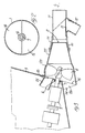
- FIG. 1 Diagrammatically shown in Figure 1 is the astern region of a vessel or watercraft, within which a tubular housing 1 is fitted, and is arranged at such a level that approximately the lower half thereof will be filled with water, as indicated by arrow L.
- a delivery duct 22 terminating with a nozzle 2 extends from the aft end side of, and is substantilly coaxial to the tubular housing 1.
- the said delivery duct 22 is arranged in the fore-and-aft direction of the vessel or watercraft, and extends out of the transom board 3 thereof.
- the water jet for propulsion of the vessel or watercraft is ejected from the rear end nozzle 2 of the delivery duct 22.
- the tubular housing 1 has its fore end side connected with a lower water-intake channel 4 which is directed toward the vessel's or watercraft's head.
- the rear end of the lower water-intake channel 4 is connected with a water-inlet opening 15 at the forward end of the tubular housing 1.
- the forward end of the water-intake channel 4 is connected with a water-intake opening 14 which is provided in the vessel's or watercraft's bottom for sucking the water surrounding the vessel.
- the said lower water-intake channel 4 is inclined downward and is directed toward the vessel's or watercraft's head.
- the tubular housing 1 is further provided at its fore end side with an auxiliary upper inlet opening 14 connected with a duct 5 which in turn is connected or connectable with the ambient air, and/or with the exhaust manifold, and/or with the duct for discharging the water cooling the vessel- or watercraft-propelling engine or engines.
- the water-inlet opening 15 provided at the foward end of the tubular housing 1 and connected through the water-intake channel 4 with the water-intake opening 14, is formed as a semicircle underneath a substantially horizontal diametrical wall which separates this lower water-inlet opening 15 from the auxiliary upper inlet opening 16.
- the auxiliary inlet opening 16 provided at the forward end of the tubular housing 1 and connected with the upper duct 5, is formed as a semicircle over the substantially horizontal diametrical wall, between the two openings 15 and 16.
- a pump impeller 8 is arranged in the tubular housing 1 and is secured to an impeller shaft 7 rotatably supported in a bushing 6 which is fixed on the partition wall between the two openings 15 and 16.
- the impeller 8 is formed as a propeller and constitutes the rotor of the suction pump of the water jet propulsion apparatus of the vessel or watercraft.
- the propeller-driving shaft 7 Owing to the propeller 8 being arranged as close as possible to the forward end of the housing 1, the propeller-driving shaft 7 does not extend, or extends only in a slight degree into the tubular housing 1, as it clearly appears in Figure 1.
- the shaft 7 driving the propeller 8 is connected as usual to the shaft of the not shown engine or engines.
- a stator 10 with spaced diffuser vanes is advantageously provided in the delivery duct 22 by which the tubular housing 1 is connected to the nozzle 2.
- the impeller 8 is fed with sea water only in part, and only into its lower half, through the water-inlet opening 15 that lies underneath the level of the axis of the propeller shaft 7, and is connected with the water-intake opening 14 through the water-intake channel 14.
- the upper half of the pump impeller 8 can be fed at will by means of the duct 5, or can be even left unfed. More particularly, the upper duct 5 can be closed and opened at will, and can be connected with the exhaust manifold of the motor, and at the same time also with the motor-cooling water discharge duct, or it can be connected only with the exhaust manifold of the motor, or only with the motor-cooling water discharge duct.
- the said upper duct 5 can be simply connected to the ambient air, or it may be even omitted and, in this instance, the forward end of the impeller housing 1 can be entirely closed over the bushing 6 and over the level of the axis of the impeller shaft.
- a means for orienting the water jet for propulsion of a vessel or watercraft, so that it performs the function of a rudder.
- This means consists of a water jet-orienting sleeve 11 which by means of diametrically opposite arms 111 is pivotably connected to the free aft end side of the delivery duct 22 ending with the nozzle 2, so as to be angularly movable in a horizontal plane, in both directions relative to the longitudinal axis of the nozzle 2.
- the water jet-orienting sleeve 11 is provided on the lower portion of its peripheral wall with a downwardly inclined, reverse motion duct 12 which is turned toward the vessel's or watercraft's head.
- a shutter member 13 is provided in the water jet-orienting sleeve 11 and is hingedly connected to the downstream rim portion - relative to the direction in which a propulsive water jet is ejected, of the opening between the solidarized reverse motion duct 12 and water jet-orienting sleeve 11.
- the hinged shutter member 13 is so mounted as to be swingable from a position in which it closes the reverse motion duct 12, into a position shown by dash-and-dot lines, in which it closes the water jet-orienting sleeve 11, and deflects the water jet flow through the reverse motion duct 12, whereby a vessel or watercraft is imparted a backward thrust.
- the motion is not reversed by reversing the direction of rotation of the pump impeller 7, or by reversing the inclination of the blades of the pump impeller 7, when the said impeller is in form of a propeller with orintable blades, but the motion is reversed simply by moving the shutter member 13 from the position shown by solid lines in Figure 1, into the position shown by dash-and-dot lines in the said Figure 1.
- the pump impeller receives sea water always in the same direction, and sends the sea water into the delivery duct 22 through its end nozzle 2.
- the pump impeller 8 is fed with sea water always through the water-inlet opening 15 lying underneath the level of the axis of the impeller shaft.
- the propeller 8 that constitutes the pump impeller of the water jet propulsion apparatus is caused to protrude from the vessel's or watercraft's transom board 3, close to the area at which the transom board is connected with the vessel's or watercraft's bottom.
- the propeller 8 may be a propeller emerging partly from the water line L. More particularly, the axis of rotation of propeller 8, and then the propeller-driving shaft 7, are inclined upwardly from the horizontal plane.
- the tubular housing 20 in which the propeller 8 is arranged consists in this embodiment of a tubular body, which is attached to the transom board 3 lower portion connected with the vessel's or watercraft's bottom.
- the tubular body 20 is provided on its aft end side with a delivery duct 22 terminating with a nozzle 2 and which is substantially equal to the delivery duct of the former embodiment.
- the said delivery duct 22 with the nozzle 2 carries a water jet-orienting sleeve 11 which is like the above described one, wherefore the members of this latter sleeve are designated by the same reference numerals.
- the tubular body 20 of the impeller housing is provided on its fore end side with a tubular lower extension arranged below the vessel's or watercraft's bottom, whereby the forward open, water-intake channel 24 is formed together with the underside of the vessel's or watercraft's bottom.
- the water-intake channel 24 is connected with the lower portion lying under the water of the impeller housing 20, and the upper duct 25 for venting the exhaust gases and/or for discharging the engine-cooling water is provided inside the astern region of a vessel or watercraft and is connected with the upper portion of the tubular impeller housing 20. Therefore, also in this embodiment, the propeller 8 dips partly into the water (arrow L indicating the water line) at least when navigating, and preferably substantially by its lower half.
- the exhaust gases from the engine or engines and/or the engine-cooling water may be fed to the propeller upper half and are thus mixed with the sucked water flow from which the propulsive water jet is formed.
- This second embodiment turns particularly to advantage, because it permits to easily convert any type of conventional propeller drive into a water jet propulsion apparatus.
- the water jet propulsion apparatus affords a higher efficiency in that any troubles in the water flow through the water-intake channel are eliminated. Thanks to the possibility of having the exhaust gases from the engine or engines mixed with the sucked water flow from which the propulsive water jet is formed, the flux density of the discharge water flow is reduced, so that any vibrations affecting the pump impeller, and so any noise generation when navigating, are abated. On the other hand, the exhaust gases from the engine or engines are also more efficaciously cooled and scrubbed by the considerable outputs of sucked water, so that a lesser air pollution will be produced.
Landscapes
- Chemical & Material Sciences (AREA)
- Engineering & Computer Science (AREA)
- Combustion & Propulsion (AREA)
- Mechanical Engineering (AREA)
- Ocean & Marine Engineering (AREA)
- Physics & Mathematics (AREA)
- Fluid Mechanics (AREA)
- Jet Pumps And Other Pumps (AREA)
- Earth Drilling (AREA)
- Excavating Of Shafts Or Tunnels (AREA)
- Structures Of Non-Positive Displacement Pumps (AREA)
- Exhaust Silencers (AREA)
Claims (14)
- Appareil de propulsion par jet d'eau pour bateau ou engin naviguant, comprenant :a) une tuyère à jet d'eau (2) s'étendant vers l'arrière ;b) une pompe-hélice entraînée par un moteur, dont l'hélice (8) est disposée dans un logement tubulaire (1, 20) et est fixée à l'extrémité arrière d'un arbre (7) s'étendant vers l'avant et entraîné par un moteur,c) un conduit de décharge (22) reliant l'extrémité arrière du logement d'hélice (1, 20) à la tuyère à jet d'eau (2) ;d) un canal d'amenée d'eau (4, 24) s'étendant vers l'avant et reliant un orifice d'entrée d'eau (15) à l'extrémité avant du logement d'hélice (1, 20) à un orifice d'entrée d'eau (14) ouvert sur l'eau entourant le bateau,
caractérisé en ce quee) l'orifice d'entrée d'eau (15), agencé à l'extrémité avant du logement d'hélice (1, 20) et reliée au canal d'amenée d'eau (4, 24), s'étend exclusivement en-dessous du niveau de l'axe de l'arbre d'hélice (7). - Appareil selon la revendication 1, caractérisé en ce que l'orifice d'entrée d'eau (15), agencé à l'extrémité avant du logement d'hélice (1, 20) en dessous du niveau de l'axe de l'arbre d'hélice (7) et relié au canal d'amenée d'eau (4, 24), est conformée en secteur de cercle dont le centre est sur l'axe de l'arbre d'hélice (7).
- Appareil selon la revendication 1, caractérisé en ce que l'orifice d'entrée d'eau (15), agencé à l'extrémité avant du logement d'hélice (1, 20) et relié au canal d'amenée d'eau (4, 24), est conformé en demi-cercle en dessous d'un diamètre sensiblement horizontal intersectant l'axe de l'arbre d'hélice (7).
- Appareil selon l'une quelconque des revendications précédentes, caractérisé en ce que l'extrémité avant du logement d'hélice (1, 20) est obturée, exception faite de l'orifice d'entrée d'eau (15) agencé en dessous du niveau de l'axe de l'arbre d'hélice (7).
- Appareil selon l'une quelconque des revendications 1 à 3, caractérisé en ce qu'un orifice d'entrée auxiliaire (16), agencé à l'extrémité avant du logement d'hélice (1, 20) au dessus du niveau de l'axe de l'arbre d'hélice (7), communique avec un conduit (5, 25) qui est relié, ou susceptible d'être relié, à l'air ambiant et/ou au collecteur d'échappement du moteur et/ou au conduit d'évacuation de l'eau de refroidissement du moteur.
- Appareil selon la revendication 5, caractérisé en ce que l'orifice d'entrée auxiliaire (16), agencé à l'extrémité avant du logement d'hélice (1, 20) au dessus du niveau de l'axe de l'arbre d'hélice (7), est conformé en secteur de cercle dont le centre est sur l'axe de l'arbre d'hélice (7), ou en demi-cercle au-dessus d'un diamètre sensiblement horizontal intersectant l'axe de l'arbre d'hélice (7).
- Appareil selon l'une quelconque des revendications précédentes, caractérisé en ce que, dans des conditions de navigation en charge normale, la ligne d'eau L est sensiblement au niveau de l'axe de l'arbre d'hélice (7).
- Appareil selon l'une quelconque des revendications précédentes, caractérisé en ce que l'arbre d'hélice (7) est monté rotatif dans un palier étanche (6) disposé aussi près que possible de l'extrémité avant du logement d'hélice (1, 20), de sorte que seule une très faible longueur de l'arbre (7) portant l'hélice (8) s'étend dans le logement d'hélice (1, 20).
- Appareil selon l'une quelconque des revendications précédentes, caractérisé en ce que l'hélice (8) est une hélice de propulsion.
- Appareil selon l'une quelconque des revendications précédentes, caractérisé en ce que le logement d'hélice (1), le canal d'amenée d'eau (4) s'étendant vers l'avant et le conduit auxiliaire (5) sont agencés dans la zone arrière du fond du bâteau ou de l'engin, juste en avant du tableau arrière (3), et en ce que le conduit de décharge (22), muni de la tuyère à jet d'eau (2), s'étend au-delà du tableau arrière.
- Appareil selon l'une quelconque des revendications 1 à 9, caractérisé en ce que l'hélice (8) est agencée en sorte de faire saillie hors du tableau arrière (3), et en ce que le logement d'hélice comprend un corps tubulaire (20) fixé extérieurement au fond du bateau ou de l'engin et comportant, à son extrémité arrière, le conduit de décharge (22) avec la tuyère à jet d'eau (2) et, à son extrémité avant, un prolongement tubulaire inférieur dirigé vers l'avant qui forme, avec la paroi extérieure du fond du bateau ou de l'engin, en particulier dans la zone où le tableau arrière (3) est relié au fond du bateau ou de l'engin, le canal d'amenée d'eau (24).
- Appareil selon l'une quelconque des revendications précédentes, caractérisé en ce qu'un stator (10) muni d'ailettes de diffusion espacées est agencé dans le conduit de décharge (22) de la pompe-hélice.
- Appareil selon l'une quelconque des revendications précédentes, caractérisé en ce que des moyens d'orientation du jet d'eau (11, 12, 13) sont agencés à l'extrémité arrière de la tuyère à jet d'eau (2), lesdits moyens d'orientation faisant office de gouvernail et d'inverseur de marche.
- Appareil selon la revendication 13, caractérisé en ce que les moyens d'orientation du jet d'eau propulsif comprennent un manchon (11) d'orientation du jet d'eau qui est monté pivotant à l'extrémité arrière libre du conduit de décharge (22) terminé par la tuyère à jet d'eau (2), en sorte d'être mobile angulairement dans un plan horizontal de part et d'autre de l'axe longitudinal dudit conduit de décharge (22) et de sa tuyère à jet d'eau (2), le manchon (11) d'orientation du jet d'eau étant muni d'un conduit inférieur (12) d'inversion de marche qui est incliné vers le bas et tourné vers l'avant, ledit manchon (11) étant également muni d'un volet d'obturation (13) mobile qui est susceptible de passer en pivotant d'une position dans laquelle il obture le conduit (12) d'inversion de marche, à une position dans laquelle il obture le manchon (11) d'orientation du jet d'eau en déviant le jet d'eau vers ledit conduit (12) d'inversion de marche.
Priority Applications (4)
| Application Number | Priority Date | Filing Date | Title |
|---|---|---|---|
| AT91113400T ATE129212T1 (de) | 1991-08-09 | 1991-08-09 | Wasserstrahlantriebsgerät. |
| EP91113400A EP0527251B1 (fr) | 1991-08-09 | 1991-08-09 | Appareil de propulsion à jet d'eau |
| DE69114002T DE69114002T4 (de) | 1991-08-09 | 1991-08-09 | Wasserstrahlantriebsgerät. |
| DE69114002A DE69114002D1 (de) | 1991-08-09 | 1991-08-09 | Wasserstrahlantriebsgerät. |
Applications Claiming Priority (1)
| Application Number | Priority Date | Filing Date | Title |
|---|---|---|---|
| EP91113400A EP0527251B1 (fr) | 1991-08-09 | 1991-08-09 | Appareil de propulsion à jet d'eau |
Publications (2)
| Publication Number | Publication Date |
|---|---|
| EP0527251A1 EP0527251A1 (fr) | 1993-02-17 |
| EP0527251B1 true EP0527251B1 (fr) | 1995-10-18 |
Family
ID=8207033
Family Applications (1)
| Application Number | Title | Priority Date | Filing Date |
|---|---|---|---|
| EP91113400A Expired - Lifetime EP0527251B1 (fr) | 1991-08-09 | 1991-08-09 | Appareil de propulsion à jet d'eau |
Country Status (3)
| Country | Link |
|---|---|
| EP (1) | EP0527251B1 (fr) |
| AT (1) | ATE129212T1 (fr) |
| DE (2) | DE69114002D1 (fr) |
Cited By (1)
| Publication number | Priority date | Publication date | Assignee | Title |
|---|---|---|---|---|
| CN106143849A (zh) * | 2016-09-28 | 2016-11-23 | 珠海蓝创科技有限公司 | 一种带防护功能的管道推进器 |
Families Citing this family (8)
| Publication number | Priority date | Publication date | Assignee | Title |
|---|---|---|---|---|
| EP0874753A4 (fr) * | 1996-01-16 | 2001-03-14 | Paulette Renee Burg | Propulsion hydropneumatique |
| GB9810169D0 (en) * | 1998-05-13 | 1998-07-08 | Wilkins Mark V | Propulsion unit |
| US6881110B1 (en) | 2003-03-03 | 2005-04-19 | Siemens Aktiengesellschaft | High-speed vessel powered by at least one water jet propulsion system without exhaust gas trail |
| CN107628214A (zh) * | 2017-08-03 | 2018-01-26 | 南京航空航天大学 | 基于旁路式无源推力矢量喷管的船用推进装置及其推进方法 |
| CN108482613B (zh) * | 2018-04-18 | 2023-08-29 | 苏州东珠龙旺消防器材有限公司 | 一种可远程遣派救援的救生浮艇 |
| CN112776966B (zh) * | 2020-09-09 | 2022-07-29 | 南京航空航天大学 | 基于流体矢量喷管的船舶推进系统及其推进方法 |
| CN113859500B (zh) * | 2021-11-11 | 2022-09-02 | 珠海市水正浮生智能科技有限公司 | 一种用于水上冲浪工具的动力装置 |
| EP4719892A2 (fr) * | 2023-05-31 | 2026-04-08 | Air Mobility, LLC | Moteur de propulsion à base de fluide |
Family Cites Families (7)
| Publication number | Priority date | Publication date | Assignee | Title |
|---|---|---|---|---|
| US3302605A (en) * | 1964-02-14 | 1967-02-07 | Tamco Ltd | Water jet propulsion apparatus |
| US3981262A (en) * | 1971-01-22 | 1976-09-21 | Sidewinder Marine, Inc. | Water jet propulsion apparatus |
| US3757728A (en) * | 1972-03-20 | 1973-09-11 | Berkeley Pump Co | Guide vane for suction side of marine jet propulsion system |
| CH571423A5 (en) * | 1973-05-29 | 1976-01-15 | Kreuger Sten | Reversible turbine for propelling motor boat - has turbine runner with blade rings of opposite pitch screened alternately |
| US3943876A (en) * | 1973-12-06 | 1976-03-16 | Kiekhaefer Aeromarine Motors, Inc. | Water jet boat drive |
| US3934538A (en) * | 1974-05-16 | 1976-01-27 | Canazzi H Donald | Boat propulsion system |
| US3976026A (en) * | 1975-03-24 | 1976-08-24 | Eastling George E | Slow speed steering control for jet-powered water craft |
-
1991
- 1991-08-09 EP EP91113400A patent/EP0527251B1/fr not_active Expired - Lifetime
- 1991-08-09 DE DE69114002A patent/DE69114002D1/de not_active Expired - Fee Related
- 1991-08-09 AT AT91113400T patent/ATE129212T1/de not_active IP Right Cessation
- 1991-08-09 DE DE69114002T patent/DE69114002T4/de not_active Expired - Lifetime
Cited By (1)
| Publication number | Priority date | Publication date | Assignee | Title |
|---|---|---|---|---|
| CN106143849A (zh) * | 2016-09-28 | 2016-11-23 | 珠海蓝创科技有限公司 | 一种带防护功能的管道推进器 |
Also Published As
| Publication number | Publication date |
|---|---|
| DE69114002D1 (de) | 1995-11-23 |
| ATE129212T1 (de) | 1995-11-15 |
| DE69114002T2 (de) | 1996-04-18 |
| EP0527251A1 (fr) | 1993-02-17 |
| DE69114002T4 (de) | 1996-12-19 |
Similar Documents
| Publication | Publication Date | Title |
|---|---|---|
| US3889623A (en) | Jet propulsion unit for boats | |
| US4304558A (en) | Marine propulsion device including propeller shroud | |
| EP0527251B1 (fr) | Appareil de propulsion à jet d'eau | |
| US20110263168A1 (en) | Gaseous fluid vessel propulsion system | |
| JP3385036B2 (ja) | ウォータージェット推進式船外機 | |
| US5066255A (en) | Drive arrangement for a planing boat | |
| US4635582A (en) | Apparatus for preventing a capsized boat from sinking | |
| US3487804A (en) | Underwater propeller with airvented slip stream | |
| US5713769A (en) | Stator and nozzle assembly for jet propelled personal watercraft | |
| US6629866B2 (en) | Marine vehicle propulsion system | |
| WO2002030741A1 (fr) | Dispositif de propulsion pour bateau | |
| US5766046A (en) | Cooling water pickup for marine propulsion unit | |
| US5700169A (en) | Inlet adapter for a personal watercraft | |
| JP4421320B2 (ja) | ウォータージェット推進型の小型滑走艇 | |
| JPH09151719A (ja) | 船舶用2サイクルエンジン | |
| JP3767726B2 (ja) | 潜水艇 | |
| US8403715B1 (en) | Marine jet drive | |
| JPH09309492A (ja) | ウォータージェット船外機 | |
| JPS62238192A (ja) | 舶用推進装置 | |
| CN112912602B (zh) | 船舶发动机组件 | |
| JP2768480B2 (ja) | 小型ジェット推進艇のウォータロック装置 | |
| EP0881142B1 (fr) | Dispositif de propulsion par jet d'eau destine a un navire | |
| JPH04342692A (ja) | 水噴射式推進船のインペラ構造 | |
| JP4628575B2 (ja) | ジェット推進型の滑走艇 | |
| US20070028824A1 (en) | Boat control system |
Legal Events
| Date | Code | Title | Description |
|---|---|---|---|
| PUAI | Public reference made under article 153(3) epc to a published international application that has entered the european phase |
Free format text: ORIGINAL CODE: 0009012 |
|
| AK | Designated contracting states |
Kind code of ref document: A1 Designated state(s): AT BE CH DE DK ES FR GB GR IT LI LU NL SE |
|
| 17P | Request for examination filed |
Effective date: 19930721 |
|
| 17Q | First examination report despatched |
Effective date: 19941215 |
|
| GRAA | (expected) grant |
Free format text: ORIGINAL CODE: 0009210 |
|
| AK | Designated contracting states |
Kind code of ref document: B1 Designated state(s): AT BE CH DE DK ES FR GB GR IT LI LU NL SE |
|
| PG25 | Lapsed in a contracting state [announced via postgrant information from national office to epo] |
Ref country code: IT Free format text: LAPSE BECAUSE OF FAILURE TO SUBMIT A TRANSLATION OF THE DESCRIPTION OR TO PAY THE FEE WITHIN THE PRE;WARNING: LAPSES OF ITALIAN PATENTS WITH EFFECTIVE DATE BEFORE 2007 MAY HAVE OCCURRED AT ANY TIME BEFORE 2007. THE CORRECT EFFECTIVE DATE MAY BE DIFFERENT FROM THE ONE RECORDED.SCRIBED TIME-LIMIT Effective date: 19951018 Ref country code: AT Effective date: 19951018 Ref country code: DK Effective date: 19951018 Ref country code: BE Effective date: 19951018 Ref country code: LI Effective date: 19951018 Ref country code: ES Free format text: THE PATENT HAS BEEN ANNULLED BY A DECISION OF A NATIONAL AUTHORITY Effective date: 19951018 Ref country code: CH Effective date: 19951018 Ref country code: GR Free format text: LAPSE BECAUSE OF FAILURE TO SUBMIT A TRANSLATION OF THE DESCRIPTION OR TO PAY THE FEE WITHIN THE PRESCRIBED TIME-LIMIT Effective date: 19951018 |
|
| REF | Corresponds to: |
Ref document number: 129212 Country of ref document: AT Date of ref document: 19951115 Kind code of ref document: T |
|
| REF | Corresponds to: |
Ref document number: 69114002 Country of ref document: DE Date of ref document: 19951123 |
|
| ET | Fr: translation filed | ||
| REG | Reference to a national code |
Ref country code: CH Ref legal event code: PL |
|
| PG25 | Lapsed in a contracting state [announced via postgrant information from national office to epo] |
Ref country code: GB Effective date: 19960809 |
|
| PLBE | No opposition filed within time limit |
Free format text: ORIGINAL CODE: 0009261 |
|
| STAA | Information on the status of an ep patent application or granted ep patent |
Free format text: STATUS: NO OPPOSITION FILED WITHIN TIME LIMIT |
|
| PG25 | Lapsed in a contracting state [announced via postgrant information from national office to epo] |
Ref country code: LU Free format text: LAPSE BECAUSE OF NON-PAYMENT OF DUE FEES Effective date: 19960831 |
|
| 26N | No opposition filed | ||
| GBPC | Gb: european patent ceased through non-payment of renewal fee |
Effective date: 19960809 |
|
| PGFP | Annual fee paid to national office [announced via postgrant information from national office to epo] |
Ref country code: SE Payment date: 19980709 Year of fee payment: 8 |
|
| PGFP | Annual fee paid to national office [announced via postgrant information from national office to epo] |
Ref country code: DE Payment date: 19980805 Year of fee payment: 8 |
|
| PGFP | Annual fee paid to national office [announced via postgrant information from national office to epo] |
Ref country code: FR Payment date: 19980827 Year of fee payment: 8 |
|
| PGFP | Annual fee paid to national office [announced via postgrant information from national office to epo] |
Ref country code: NL Payment date: 19980831 Year of fee payment: 8 |
|
| PG25 | Lapsed in a contracting state [announced via postgrant information from national office to epo] |
Ref country code: SE Free format text: THE PATENT HAS BEEN ANNULLED BY A DECISION OF A NATIONAL AUTHORITY Effective date: 19990830 |
|
| PG25 | Lapsed in a contracting state [announced via postgrant information from national office to epo] |
Ref country code: NL Free format text: LAPSE BECAUSE OF NON-PAYMENT OF DUE FEES Effective date: 20000301 |
|
| PG25 | Lapsed in a contracting state [announced via postgrant information from national office to epo] |
Ref country code: FR Free format text: LAPSE BECAUSE OF NON-PAYMENT OF DUE FEES Effective date: 20000428 |
|
| EUG | Se: european patent has lapsed |
Ref document number: 91113400.5 |
|
| NLV4 | Nl: lapsed or anulled due to non-payment of the annual fee |
Effective date: 20000301 |
|
| PG25 | Lapsed in a contracting state [announced via postgrant information from national office to epo] |
Ref country code: DE Free format text: LAPSE BECAUSE OF NON-PAYMENT OF DUE FEES Effective date: 20000601 |
|
| REG | Reference to a national code |
Ref country code: FR Ref legal event code: ST |