EP0528140A2 - Magnetisches Aufzeichnungs-/Wiedergabegerät - Google Patents
Magnetisches Aufzeichnungs-/Wiedergabegerät Download PDFInfo
- Publication number
- EP0528140A2 EP0528140A2 EP92110595A EP92110595A EP0528140A2 EP 0528140 A2 EP0528140 A2 EP 0528140A2 EP 92110595 A EP92110595 A EP 92110595A EP 92110595 A EP92110595 A EP 92110595A EP 0528140 A2 EP0528140 A2 EP 0528140A2
- Authority
- EP
- European Patent Office
- Prior art keywords
- recording
- magnetic head
- data
- record current
- erase
- Prior art date
- Legal status (The legal status is an assumption and is not a legal conclusion. Google has not performed a legal analysis and makes no representation as to the accuracy of the status listed.)
- Granted
Links
Images


Classifications
-
- G—PHYSICS
- G11—INFORMATION STORAGE
- G11B—INFORMATION STORAGE BASED ON RELATIVE MOVEMENT BETWEEN RECORD CARRIER AND TRANSDUCER
- G11B20/00—Signal processing not specific to the method of recording or reproducing; Circuits therefor
- G11B20/02—Analogue recording or reproducing
-
- G—PHYSICS
- G11—INFORMATION STORAGE
- G11B—INFORMATION STORAGE BASED ON RELATIVE MOVEMENT BETWEEN RECORD CARRIER AND TRANSDUCER
- G11B19/00—Driving, starting, stopping record carriers not specifically of filamentary or web form, or of supports therefor; Control thereof; Control of operating function ; Driving both disc and head
- G11B19/02—Control of operating function, e.g. switching from recording to reproducing
- G11B19/04—Arrangements for preventing, inhibiting, or warning against double recording on the same blank or against other recording or reproducing malfunctions
-
- G—PHYSICS
- G11—INFORMATION STORAGE
- G11B—INFORMATION STORAGE BASED ON RELATIVE MOVEMENT BETWEEN RECORD CARRIER AND TRANSDUCER
- G11B20/00—Signal processing not specific to the method of recording or reproducing; Circuits therefor
- G11B20/10—Digital recording or reproducing
-
- G—PHYSICS
- G11—INFORMATION STORAGE
- G11B—INFORMATION STORAGE BASED ON RELATIVE MOVEMENT BETWEEN RECORD CARRIER AND TRANSDUCER
- G11B20/00—Signal processing not specific to the method of recording or reproducing; Circuits therefor
- G11B20/10—Digital recording or reproducing
- G11B20/12—Formatting, e.g. arrangement of data block or words on the record carriers
- G11B20/1217—Formatting, e.g. arrangement of data block or words on the record carriers on discs
- G11B20/1252—Formatting, e.g. arrangement of data block or words on the record carriers on discs for discontinuous data, e.g. digital information signals or computer program data
-
- G—PHYSICS
- G11—INFORMATION STORAGE
- G11B—INFORMATION STORAGE BASED ON RELATIVE MOVEMENT BETWEEN RECORD CARRIER AND TRANSDUCER
- G11B5/00—Recording by magnetisation or demagnetisation of a record carrier; Reproducing by magnetic means; Record carriers therefor
- G11B5/012—Recording on, or reproducing or erasing from, magnetic disks
- G11B5/016—Recording on, or reproducing or erasing from, magnetic disks using magnetic foils
-
- G—PHYSICS
- G11—INFORMATION STORAGE
- G11B—INFORMATION STORAGE BASED ON RELATIVE MOVEMENT BETWEEN RECORD CARRIER AND TRANSDUCER
- G11B2220/00—Record carriers by type
- G11B2220/20—Disc-shaped record carriers
- G11B2220/25—Disc-shaped record carriers characterised in that the disc is based on a specific recording technology
- G11B2220/2508—Magnetic discs
Definitions
- This invention relates to a magnetic recording/reproducing apparatus, and is more particularly suitably to apply to a floppy disc device for example.
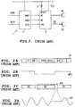
- the desired data are recordable and reproducible by use of an integrated control circuit 2 and a write/read circuit 4 illustrated in Fig. 3.
- a control command COMD is inputted to the control circuit 2 from, e.g., a computer, and, at the same time, input data DATA are also inputted thereto.
- the control circuit 2 herein changes over an operation mode of the floppy disk device 1 in conformity with the control command COMD and drives a mechanical drive circuit (unillustrated) according to the necessity.
- the control circuit 2 causes a fall of an erase control signal XERS and outputs it to the write/read circuit 4, thereby driving an erase magnetic head 6A for a predetermined period.
- control circuit 2 simultaneously causes a fall of a write control signal XWGO and sets the write/read circuit 4 in the recording mode. Thereafter, the control circuit 2 sequentially outputs predetermined record data XWDO.
- the write/read circuit 4 supplies, when the erase control signal XERS has fallen, a predetermined DC current to the erase magnetic head 6A.
- the erase magnetic head 6A is herein constructed integrally with a recording/reproducing magnetic head 6B.
- the magnetic head 6A is arranged to scan a floppy disc in advance of the recording/reproducing magnetic head 6B, thereby erasing the recorded data beforehand with respect to an area scanned by the recording/reproducing magnetic head 6B during a falling period of the erase control signal XERS.
- the write/read circuit 4 drives, when being set in the recording mode, the recording/reproducing magnetic head 6B by a record current IW determined by an externally attached record current setting resistor 8 in accordance with the record data XWDO sequentially inputted.
- the input data DATA are sequentially thereby recordable in a predetermined format.
- the input data are recorded on respective recording tracks TR (Fig. 2A) on the sector unit.
- predetermined gaps 2 and 3 are formed in front and in rear of the respective input data.
- the erase magnetic head 6A is risen in an area of the gap 2, and simultaneously the recording/reproducing magnetic head is fallen in an area of the gap 2, by the falling of write control command WEN (Fig. 2B).
- the erase magnetic head 6B erases an extra non-record data area by scanning the area ARE in which the erase magnetic head 6A proceeds with respect to the recording/reproducing magnetic head 6B.
- a regenerative clock is hard to extract during a period for which the magnetic head 6B scans the abovementioned area when effecting the reproduction. This presents such a problem that the operation of a regenerative system as a whole becomes unstable.
- an object of this invention is to provide a magnetic recording/reproducing apparatus capable of causing the regenerative system to stably operate.
- a magnetic recording/reproducing device 10 in which a succeeding recording/reproducing magnetic head 6B scans an area ARE scanned by an erase magnetic head 6A in a recording mode, a predetermined record current IW is at the same time supplied to the recording/reproducing magnetic head 6B by changing over a polarity of the record current IW in accordance with input data DATA, and the input data DATA is recorded on a predetermined recording medium through the recording/reproducing magnetic head, wherein data (4E) erased by the erase magnetic head 6A is recorded in the area ARE erased by the erase magnetic head 6A after stopping an erasing operation of the erase magnetic head 6A, and the recording mode is thus ended.
- the record current IW is gradually fallen down substantiality a 0 level when recording the erased data (4E).
- a magnetic recording/reproducing device 10 in which a succeeding recording/reproducing magnetic head 6B scans an area ARE scanned by an erase magnetic head 6A in a recording mode, a predetermined record current IW is at the same time supplied to the recording/reproducing magnetic head 6B by changing over a polarity of the record current IW in accordance with input data DATA, and the input data DATA is recorded on a predetermined recording medium through the recording/reproducing magnetic head 6B, wherein data (4E) erased by the erase magnetic head 6A is recorded in the area ARE erased by the erase magnetic head 6A after stopping an erasing operation of the erase magnetic head 6A, subsequently erase data DS in which the polarity is changed over at a constant cycle is recorded in a state where the record current IW is gradually fallen, and the recording mode is thus ended.
- a magnetic recording/reproducing device 20 for recording predetermined input data DATA on a magnetic recording medium in a recording mode, reproducing the data recorded on the recording medium in a reproducing mode and outputting the data, which comprises: a recording/reproducing magnetic head 6B; record current control circuits 12, 14, and 16 for controlling a record current IW of the magnetic head 6B; and a write circuit 4 for outputting the record current IW to the magnetic head 6B by changing over a polarity of the record current IW and thereafter outputting the record current IW to the magnetic head 6B by changing over the polarity of the record current IW in accordance with demagnetization data DS for a predetermined period in the recording mode, the record current being gradually fallen down substantially to a 0 level during a period for which the demagnetization data DS are recorded with the result that the recording mode is ended.
- the record current control circuit 12, 14, and 16 hold the record current to a predetermined value at a rise of the record mode.
- the data (4E) erased by the erase magnetic head 6A is recorded in the area ARE erased by the erase magnetic head 6A, and the recording mode is ended.
- the regenerative signal can be thereby obtained also from the area which is erased extra by the erase magnetic head 6A.
- the operation of the regenerative system can be stabilized, correspondingly.
- the record current IW is gradually fallen down substantially to the 0 level, whereby the C/N ratio of the regenerative signal SRF can be improved.
- the record current IW is outputted to the magnetic head 6B by changing over the polarity of the record current IW in accordance with the input data DATA. Thereafter, the record current IW is outputted to the magnetic head 6B by changing over the polarity of the record current IW in accordance with the demagnetization data DS for a predetermined period. During a period for recording the demagnetization data DS, the record current IW is gradually fallen down substantially to the 0 level, and the recording mode is ended. It is therefore possible to surely demagnetize the magnetic head 6B.
- the record current IW is held to a predetermined value. Even when demagnetizing the magnetic head, the data is surely recordable from the start of recording.
- a floppy disc device designated generally at 10 in Fig. 1 controls a write/read circuit 14 by a control circuit 11.
- an erase control signal XERS (Fig. 4C) are outputted by a write control command WEN (Fig. 4B) at the same timing with the control circuit 2 (Fig. 1) to the recording tracks TR (Fig. 4A).
- the write/read circuit 14 is thereby controlled.
- control circuit 11 causes, after causing a fall of a write gate signal XWGO (Fig. 4D) concurrently with the write control command WEN, a rise of the write control command WEN and also causes, after a predetermined period has elapsed, a rise of the write gate signal XWGO.
- the recording/reproducing magnetic head 6B is held in a recording state till the recording/reproducing magnetic head 6B completely scans the area erased by the erase magnetic head 6A.
- control circuit 11 outputs the input data in a predetermined format during a falling period of the write control command WEN, generates predetermined data inwardly during a period from a rising of the write control command WEN to a falling of the write gate signal XWGO, and outputs the data generated inwardly following the input data DATA.
- the erase magnetic head 6A performs the record in the area erased by the erase magnetic head 6A without exception. A discontinuity of the regenerative signals SRF is thereby prevented.
- the write/read circuit 4 inwardly generates the data (corresponding to the input data of a value 4E in this embodiment) to be recorded in the gap 3 as the relevant data.
- the data concerned is thus recorded (Fig. 4E).
- the pre-erase data is rerecorded in the area which is erased extra by the precedent erase magnetic head 6A, and the generation of an unrecorded portion is effectively prevented.
- the data recorded in the area concerned is rerecorded in the area erased extra by the precedent erase magnetic head.
- the regenerative signal is also thereby obtainable from the area erased extra by the erase magnetic head, thereby stabilizing the operation of the whole of the regenerative system by surely extracting the regenerative clock.
- a floppy disc device 20 supplies a power supply Vcc to a record current setting resistor 8 through a transistor 12.
- a capacitor 13 is connected between a base and a collector of the transistor 12, whereby the power supply Vcc is supplied via a resistor 16 to the base.
- control circuit 22 rises a signal level of a demagnetizing control signal DMAG during a period for which the recording/reproducing magnetic head 6B scans the area which is erased extra by the erase magnetic head 6A.
- the terminal voltage of the record current setting resistor 8 is gradually fallen.
- the record current IW is fallen down substantially to a 0 level just before completing the scan over the relevant area.
- the record current IW is gradually fallen, whereby a residual magnetization of the recording/reproducing magnetic head 6B can be reduced.
- the recording/reproducing magnetic head 6B can be thereby demagnetized by effectively utilizing the area erased extra by the erase magnetic head 6A.
- the operation of the regenerative system is stabilizing by causing the gradual fall of the record current and rerecording the pre-erase data in the extra-erased area. Simultaneously, the C/N ratio of the regenerative signal can be improved.
- the pre-erase data (4E) is recorded for a predetermined period in the area erased extra by the erase magnetic head 6A. Thereafter, the predetermined erase data DS is subsequently recorded.
- the record current is inverted at a clock cycle of the record data, thereby generating the data having a duty ratio of 50 [%].
- the data is recorded as the record data DS on the floppy disc.
- the demagnetization data having duty ratio of 50 [%] as shown in Fig. 8 is generated in this way and recorded while causing the gradual fall of the record current.
- the recording/reproducing magnetic head 6B can be thereby surely demagnetized.
- the C/N ratio of the regenerative signal can be improved, correspondingly.
- pre-erase data is rerecorded in combination,thus stabilizing the operation of the regenerative system.
- a capacitor 13 is charged with the electricity for standing by the record of the subsequent record data. The data immediately after starting the record can be surely recorded, correspondingly.
- the C/N ratio of the regenerative signal can be improved without deteriorating the data just after starting the record. Besides, a peak shift of the regenerative signal and an asymmetrical property can be improved.
- the embodiment discussed above has dealt with the case where the present invention is applied to the floppy disc device in which the demagnetization magnetic head and the recording/reproducing magnetic head are integrally formed.
- the present invention is not, however, limited to this.
- the present invention is applicable to various floppy disc devices and further widely to a variety of recording/reproducing devices such as hard disc devices without being limited to the floppy disc devices.
- the pre-erase data is rerecorded in the area erased extra by the erase magnetic head, thereby surely extracting the regenerative clock at the reproducing time.
- the operation of the regenerative system can be stabilized, correspondingly.
Landscapes
- Engineering & Computer Science (AREA)
- Signal Processing (AREA)
- General Engineering & Computer Science (AREA)
- Digital Magnetic Recording (AREA)
- Management Or Editing Of Information On Record Carriers (AREA)
- Signal Processing For Digital Recording And Reproducing (AREA)
Applications Claiming Priority (4)
| Application Number | Priority Date | Filing Date | Title |
|---|---|---|---|
| JP178754/91 | 1991-06-24 | ||
| JP17875691A JPH052708A (ja) | 1991-06-24 | 1991-06-24 | 磁気記録再生装置 |
| JP17875491A JPH052707A (ja) | 1991-06-24 | 1991-06-24 | 磁気記録再生装置 |
| JP178756/91 | 1991-06-24 |
Publications (3)
| Publication Number | Publication Date |
|---|---|
| EP0528140A2 true EP0528140A2 (de) | 1993-02-24 |
| EP0528140A3 EP0528140A3 (en) | 1993-11-03 |
| EP0528140B1 EP0528140B1 (de) | 1997-10-08 |
Family
ID=26498846
Family Applications (1)
| Application Number | Title | Priority Date | Filing Date |
|---|---|---|---|
| EP92110595A Expired - Lifetime EP0528140B1 (de) | 1991-06-24 | 1992-06-24 | Magnetisches Aufzeichnungs-/Wiedergabegerät |
Country Status (4)
| Country | Link |
|---|---|
| US (1) | US5359470A (de) |
| EP (1) | EP0528140B1 (de) |
| KR (1) | KR100268624B1 (de) |
| DE (1) | DE69222600T2 (de) |
Families Citing this family (1)
| Publication number | Priority date | Publication date | Assignee | Title |
|---|---|---|---|---|
| US7088537B2 (en) * | 2004-03-09 | 2006-08-08 | Seagate Technology Llc | Removing residual magnetization in a data transducer |
Family Cites Families (9)
| Publication number | Priority date | Publication date | Assignee | Title |
|---|---|---|---|---|
| US4471403A (en) * | 1983-10-04 | 1984-09-11 | The United States Of America As Represented By The United States Department Of Energy | Biasing and fast degaussing circuit for magnetic materials |
| US5214545A (en) * | 1983-11-02 | 1993-05-25 | Canon Kabushiki Kaisha | Signal erasing apparatus |
| JPH0610845B2 (ja) * | 1984-02-18 | 1994-02-09 | ティアツク株式会社 | デジタル磁気記録再生装置 |
| US4821127A (en) * | 1985-10-18 | 1989-04-11 | Fuji Photo Film Co., Ltd. | Demagnetizing apparatus for erasing signals recorded on concentric tracks |
| JPS63104262A (ja) * | 1986-10-22 | 1988-05-09 | Asaka:Kk | デイスク状情報記録再生装置 |
| JPH0264903A (ja) * | 1988-08-30 | 1990-03-05 | Toshiba Corp | 磁気記録再生装置のデータ書込み回路 |
| US4970621A (en) * | 1988-09-09 | 1990-11-13 | Hewlett-Packard Company | Demagnetization of thin film magnetic recording transducers utilizing a decreasing AC current |
| US4956788A (en) * | 1988-11-28 | 1990-09-11 | University Of The Pacific | PC-based FT/ICR system |
| US5168395A (en) * | 1990-05-02 | 1992-12-01 | International Business Machines Corporation | Controlled magnetic recording head relaxation in a magnetic recording system |
-
1992
- 1992-06-22 US US07/901,939 patent/US5359470A/en not_active Expired - Fee Related
- 1992-06-23 KR KR1019920010877A patent/KR100268624B1/ko not_active Expired - Fee Related
- 1992-06-24 DE DE69222600T patent/DE69222600T2/de not_active Expired - Fee Related
- 1992-06-24 EP EP92110595A patent/EP0528140B1/de not_active Expired - Lifetime
Also Published As
| Publication number | Publication date |
|---|---|
| KR100268624B1 (ko) | 2000-10-16 |
| EP0528140B1 (de) | 1997-10-08 |
| KR930001183A (ko) | 1993-01-16 |
| EP0528140A3 (en) | 1993-11-03 |
| DE69222600T2 (de) | 1998-02-05 |
| DE69222600D1 (de) | 1997-11-13 |
| US5359470A (en) | 1994-10-25 |
Similar Documents
| Publication | Publication Date | Title |
|---|---|---|
| US5469422A (en) | Writing and erasing information by varying the temperature of an optical recording medium | |
| CN100377213C (zh) | 具有消除记录磁头的剩磁的功能的磁头放大器电路 | |
| EP0528140B1 (de) | Magnetisches Aufzeichnungs-/Wiedergabegerät | |
| US4901169A (en) | Data recording apparatus able to accurately access a floppy disk regardless of recording density | |
| JPH0264903A (ja) | 磁気記録再生装置のデータ書込み回路 | |
| US4633337A (en) | Floppy disk driving with suitable on-delay and off-delay timing | |
| US4841383A (en) | Control pulse recording circuit for magnetic recording and reproducing apparatus | |
| JP5016446B2 (ja) | サーボ信号記録方法、サーボ信号記録装置、および磁気記録媒体 | |
| US7773466B2 (en) | Disk tray mechanism for reproducing apparatus | |
| JPH052707A (ja) | 磁気記録再生装置 | |
| JP2568541B2 (ja) | クロスト−ク低減装置 | |
| JPH052708A (ja) | 磁気記録再生装置 | |
| JP2586363B2 (ja) | 磁気ディスク装置 | |
| US6185061B1 (en) | Semiconductor integrated circuit device for use in a magnetic disk drive with reduced recovery time between operations | |
| JP2674885B2 (ja) | フロッピィディスク装置 | |
| JP2606529B2 (ja) | ディスク装置 | |
| JPH03238602A (ja) | 光磁気ディスクドライブ装置の印加磁界発生用電磁石駆動回路およびその駆動方法 | |
| JPS58125203A (ja) | 磁気記録再生装置 | |
| JPH04177602A (ja) | 磁気ディスク装置 | |
| JPH06162510A (ja) | 光ディスク装置 | |
| JPS6048812B2 (ja) | 全幅信号消去用磁気ヘツドの駆動回路 | |
| JPS58187013U (ja) | 磁気記録再生装置 | |
| JPH08249613A (ja) | 複合型磁気ヘッド | |
| JPH0573910A (ja) | 光デイスク記録装置 | |
| JPH07249245A (ja) | 情報信号消去方法 |
Legal Events
| Date | Code | Title | Description |
|---|---|---|---|
| PUAI | Public reference made under article 153(3) epc to a published international application that has entered the european phase |
Free format text: ORIGINAL CODE: 0009012 |
|
| AK | Designated contracting states |
Kind code of ref document: A2 Designated state(s): DE FR GB |
|
| PUAL | Search report despatched |
Free format text: ORIGINAL CODE: 0009013 |
|
| AK | Designated contracting states |
Kind code of ref document: A3 Designated state(s): DE FR GB |
|
| 17P | Request for examination filed |
Effective date: 19940405 |
|
| 17Q | First examination report despatched |
Effective date: 19951002 |
|
| GRAG | Despatch of communication of intention to grant |
Free format text: ORIGINAL CODE: EPIDOS AGRA |
|
| GRAH | Despatch of communication of intention to grant a patent |
Free format text: ORIGINAL CODE: EPIDOS IGRA |
|
| GRAH | Despatch of communication of intention to grant a patent |
Free format text: ORIGINAL CODE: EPIDOS IGRA |
|
| GRAA | (expected) grant |
Free format text: ORIGINAL CODE: 0009210 |
|
| AK | Designated contracting states |
Kind code of ref document: B1 Designated state(s): DE FR GB |
|
| REF | Corresponds to: |
Ref document number: 69222600 Country of ref document: DE Date of ref document: 19971113 |
|
| ET | Fr: translation filed | ||
| PLBE | No opposition filed within time limit |
Free format text: ORIGINAL CODE: 0009261 |
|
| STAA | Information on the status of an ep patent application or granted ep patent |
Free format text: STATUS: NO OPPOSITION FILED WITHIN TIME LIMIT |
|
| 26N | No opposition filed | ||
| PGFP | Annual fee paid to national office [announced via postgrant information from national office to epo] |
Ref country code: FR Payment date: 20010611 Year of fee payment: 10 |
|
| PGFP | Annual fee paid to national office [announced via postgrant information from national office to epo] |
Ref country code: DE Payment date: 20010618 Year of fee payment: 10 |
|
| PGFP | Annual fee paid to national office [announced via postgrant information from national office to epo] |
Ref country code: GB Payment date: 20010620 Year of fee payment: 10 |
|
| REG | Reference to a national code |
Ref country code: GB Ref legal event code: IF02 |
|
| PG25 | Lapsed in a contracting state [announced via postgrant information from national office to epo] |
Ref country code: GB Free format text: LAPSE BECAUSE OF NON-PAYMENT OF DUE FEES Effective date: 20020624 |
|
| PG25 | Lapsed in a contracting state [announced via postgrant information from national office to epo] |
Ref country code: DE Free format text: LAPSE BECAUSE OF NON-PAYMENT OF DUE FEES Effective date: 20030101 |
|
| GBPC | Gb: european patent ceased through non-payment of renewal fee |
Effective date: 20020624 |
|
| PG25 | Lapsed in a contracting state [announced via postgrant information from national office to epo] |
Ref country code: FR Free format text: LAPSE BECAUSE OF NON-PAYMENT OF DUE FEES Effective date: 20030228 |
|
| REG | Reference to a national code |
Ref country code: FR Ref legal event code: ST |