EP0528589A2 - Réfracteur pour éclairage extérieur - Google Patents
Réfracteur pour éclairage extérieur Download PDFInfo
- Publication number
- EP0528589A2 EP0528589A2 EP92307172A EP92307172A EP0528589A2 EP 0528589 A2 EP0528589 A2 EP 0528589A2 EP 92307172 A EP92307172 A EP 92307172A EP 92307172 A EP92307172 A EP 92307172A EP 0528589 A2 EP0528589 A2 EP 0528589A2
- Authority
- EP
- European Patent Office
- Prior art keywords
- light
- light fixture
- refracting lens
- light source
- fixture according
- Prior art date
- Legal status (The legal status is an assumption and is not a legal conclusion. Google has not performed a legal analysis and makes no representation as to the accuracy of the status listed.)
- Withdrawn
Links
- 238000007373 indentation Methods 0.000 claims description 6
- 239000000463 material Substances 0.000 description 5
- 230000000712 assembly Effects 0.000 description 4
- 238000000429 assembly Methods 0.000 description 4
- 238000009434 installation Methods 0.000 description 3
- 230000003292 diminished effect Effects 0.000 description 2
- 238000012423 maintenance Methods 0.000 description 2
- 239000000049 pigment Substances 0.000 description 2
- 239000004033 plastic Substances 0.000 description 2
- 230000001681 protective effect Effects 0.000 description 2
- 241000196324 Embryophyta Species 0.000 description 1
- 241001465754 Metazoa Species 0.000 description 1
- 229910052782 aluminium Inorganic materials 0.000 description 1
- XAGFODPZIPBFFR-UHFFFAOYSA-N aluminium Chemical compound [Al] XAGFODPZIPBFFR-UHFFFAOYSA-N 0.000 description 1
- 230000005540 biological transmission Effects 0.000 description 1
- 239000000356 contaminant Substances 0.000 description 1
- 238000005260 corrosion Methods 0.000 description 1
- 230000007797 corrosion Effects 0.000 description 1
- 238000005034 decoration Methods 0.000 description 1
- 230000007423 decrease Effects 0.000 description 1
- 230000003247 decreasing effect Effects 0.000 description 1
- 229910003460 diamond Inorganic materials 0.000 description 1
- 239000010432 diamond Substances 0.000 description 1
- 230000003467 diminishing effect Effects 0.000 description 1
- 238000006073 displacement reaction Methods 0.000 description 1
- 239000000428 dust Substances 0.000 description 1
- 230000005611 electricity Effects 0.000 description 1
- 238000003780 insertion Methods 0.000 description 1
- 230000037431 insertion Effects 0.000 description 1
- 229910052751 metal Inorganic materials 0.000 description 1
- 239000002184 metal Substances 0.000 description 1
- 230000036961 partial effect Effects 0.000 description 1
- 239000004417 polycarbonate Substances 0.000 description 1
- 229920000515 polycarbonate Polymers 0.000 description 1
- 229920000642 polymer Polymers 0.000 description 1
- 230000002829 reductive effect Effects 0.000 description 1
- 230000000717 retained effect Effects 0.000 description 1
- 229910001220 stainless steel Inorganic materials 0.000 description 1
- 239000010935 stainless steel Substances 0.000 description 1
- 238000013022 venting Methods 0.000 description 1
Images


Classifications
-
- F—MECHANICAL ENGINEERING; LIGHTING; HEATING; WEAPONS; BLASTING
- F21—LIGHTING
- F21V—FUNCTIONAL FEATURES OR DETAILS OF LIGHTING DEVICES OR SYSTEMS THEREOF; STRUCTURAL COMBINATIONS OF LIGHTING DEVICES WITH OTHER ARTICLES, NOT OTHERWISE PROVIDED FOR
- F21V5/00—Refractors for light sources
- F21V5/02—Refractors for light sources of prismatic shape
-
- F—MECHANICAL ENGINEERING; LIGHTING; HEATING; WEAPONS; BLASTING
- F21—LIGHTING
- F21S—NON-PORTABLE LIGHTING DEVICES; SYSTEMS THEREOF; VEHICLE LIGHTING DEVICES SPECIALLY ADAPTED FOR VEHICLE EXTERIORS
- F21S8/00—Lighting devices intended for fixed installation
- F21S8/08—Lighting devices intended for fixed installation with a standard
- F21S8/081—Lighting devices intended for fixed installation with a standard of low-built type, e.g. landscape light
-
- F—MECHANICAL ENGINEERING; LIGHTING; HEATING; WEAPONS; BLASTING
- F21—LIGHTING
- F21V—FUNCTIONAL FEATURES OR DETAILS OF LIGHTING DEVICES OR SYSTEMS THEREOF; STRUCTURAL COMBINATIONS OF LIGHTING DEVICES WITH OTHER ARTICLES, NOT OTHERWISE PROVIDED FOR
- F21V21/00—Supporting, suspending, or attaching arrangements for lighting devices; Hand grips
- F21V21/08—Devices for easy attachment to any desired place, e.g. clip, clamp, magnet
- F21V21/0824—Ground spikes
-
- F—MECHANICAL ENGINEERING; LIGHTING; HEATING; WEAPONS; BLASTING
- F21—LIGHTING
- F21V—FUNCTIONAL FEATURES OR DETAILS OF LIGHTING DEVICES OR SYSTEMS THEREOF; STRUCTURAL COMBINATIONS OF LIGHTING DEVICES WITH OTHER ARTICLES, NOT OTHERWISE PROVIDED FOR
- F21V5/00—Refractors for light sources
- F21V5/04—Refractors for light sources of lens shape
-
- F—MECHANICAL ENGINEERING; LIGHTING; HEATING; WEAPONS; BLASTING
- F21—LIGHTING
- F21W—INDEXING SCHEME ASSOCIATED WITH SUBCLASSES F21K, F21L, F21S and F21V, RELATING TO USES OR APPLICATIONS OF LIGHTING DEVICES OR SYSTEMS
- F21W2131/00—Use or application of lighting devices or systems not provided for in codes F21W2102/00-F21W2121/00
- F21W2131/10—Outdoor lighting
-
- F—MECHANICAL ENGINEERING; LIGHTING; HEATING; WEAPONS; BLASTING
- F21—LIGHTING
- F21W—INDEXING SCHEME ASSOCIATED WITH SUBCLASSES F21K, F21L, F21S and F21V, RELATING TO USES OR APPLICATIONS OF LIGHTING DEVICES OR SYSTEMS
- F21W2131/00—Use or application of lighting devices or systems not provided for in codes F21W2102/00-F21W2121/00
- F21W2131/10—Outdoor lighting
- F21W2131/109—Outdoor lighting of gardens
Definitions
- the present invention relates to light fixtures and more particularly to refracting lenses for outdoor light fixtures.
- outdoor light fixtures are widely known. Such fixtures typically are used to illuminate gardens, outdoor walkways, driveways, patios and other areas or to floodlight sculptures, trees, structures and other objects.
- low voltage outdoor light fixtures are constructed of metal or plastic, and have a power source, a stake for being inserted into the ground and for supporting the other parts of the light fixture, a light bulb, and a globe assembly that protects the light bulb, diffuses light emitted from the light bulb and provides decoration.
- solar panels are used to generate power for the light bulb.
- a low voltage power supply provides typically about 12 volts AC through a wire that runs, e.g., underground, from the low voltage power supply to the lightfixtures.
- the globe assembly generally serves a number of purposes, including: mounting the light bulb, conductively connecting the light bulb to a wire, protecting the light bulb, shielding the light bulb and associated electrical elements from dust and other contaminants, diffusing or redirecting the light emitted from the light bulb, and providing a decorative appearance.
- Known globe assemblies incorporating translucent pigments, frosted surfaces or ribs possess a number of known disadvantages.
- One such disadvantage is diminished light output. Diminished tight output occurs in frosted and translucent lenses and commonly is seen in commercial globe assemblies incorporating ribbed lenses.
- a further disadvantage is that incorporating the refracting lens in the globe assembly decreases design flexibility. Often clear or unpatterned globe assemblies are preferable for aesthetic as well as functional reasons, such as efficient light transmission and staying cleaner in dusty outdoor conditions.
- the present invention alleviates to a great extent the disadvantages of previously known light fixtures by providing a light fixture that comprises a globe assembly that has a clear pane and an inner refracting lens that fits over a light bulb.
- the light fixture also comprises a stake for mounting the light fixture in the ground, a light bulb, apparatus for mounting the light bulb, apparatus for connecting the fixture to a power source such as a conductive wire, and apparatus for mounting the globe and inner refracting lens.
- An advantage of the present invention is that the refracting lens is separate from the globe assembly, thereby providing greater design flexibility in that the lens incorporated in the globe assembly may be completely clear, or may incorporate various design features such as patterned, ribbed or frosted panes or portions of panes.
- a further advantage of the present invention is that the proportion of light transmitted is increased in embodiments having a clear or partially clear globe assembly.
- Yet another advantage of the present invention is that at least a portion of the globe assembly is clear, thereby aiding in installation and maintenance by providing a view of the interior of the elements of the fixture.
- FIGS. 1-3 illustrate an outdoor light fixture according to the present invention.
- Electric current is provided by insulated wire 10.
- the wire preferably is retained in place by tabs 20 that protrude from stake 30.
- power is provided by solar panels that generate an electric current.
- power is provided by batteries.
- a globe assembly 40 is mounted to the light fixture. Any type of globe assembly 40 may be used which permits light to be emitted.
- Globe assembly 40 illustrated in FIG. 1 has, inter alia, a clear pane 50, a louver 55 and top 60.
- Various types of globe assemblies that may be used in alternate embodiments of the present invention are illustrated in co-pending, commonly-assigned United States design patent applications Serial Nos. 07/696,521, 07/696,528 and 07/696,531, all filed on May 7, 1991.
- a portion of the globe assembly 40 is clear in order to maximize the amount of light passing from the light bulb 70 through the globe.
- Having a clear or partially clear globe assembly 40 also provides a view of the interior of the globe for decorative purposes and to assist in installation and repair.
- the globe assembly 40 may be mounted to the light fixture using any structure that provides sufficient stability.
- the mounting structure is adapted to conditions typical of outdoor use, such as heavy wind, rain or snow. Suitable mounting structures include hooks 75, tabs or snaps.
- An inner refracting lens 80 is mounted to the light fixture.
- the inner refracting 80 lens is mounted to bulb assembly 90 at the top of stake 30 such that it covers light bulb 70.
- the inner refracting lens 80 may be mounted to the stake or to a mounting assembly. Any means for mounting the inner refracting lens 80 may be used, such as hooks, tabs, threads or snaps 91.
- the inner refracting lens 80 preferably has a generally spherical shape with flat ends, but other shapes also may be used.
- the ends preferably define openings 92, 95.
- the opening defined by the bottom end 92 is constructed such that the inner refracting lens 80 fits over the light bulb 70 and snaps into place using snap 91.
- Light bulb 70 thereby sits within the interior of the inner refracting lens 80.
- the light bulb 70 preferably does not protrude from the opening at the top end 95.
- the top end opening 95 provides thermal venting of heat generated by light bulb 70.
- the amount of light from the top of the light bulb 70 is maximized because there is no obstruction from the inner refracting lens 80, but it is reflected in a generally downward direction, thereby diminishing hot spots.
- the light bulb 70 is inserted into bulb receiving elements 98 and then the inner refracting lens 80 is fitted over the light bulb 70 through the bottom opening 92.
- the inner refracting lens 80 is mounted first and then the light bulb 70 is fitted through the top opening 95 of the inner refracting lens and inserted into bulb receiving elements 98.
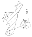
- the outer surface of inner refracting lens 80 preferably has ridges that are arranged such that they refract light emitted by the light bulb 70.
- Other arrangements for refracting light also may be used, such as dimples or polygon shaped ridges on a surface of the inner refracting lens 80. Frosting may be used to soften the light emitted.
- the ridges are arranged so as to maximize the amount of light being transmitted through the inner refracting lens 80.
- the ridges 102 preferably are separated by generally "V" shaped indentations 104 that are spaced apart from each other. Light passing through the arcuate top surface 106 of the ridge 102 generally is not refracted.
- the width of the top of each ridge is less than the length of the filament 107 of the light bulb 70, if a filament-type light source is used. The amount of unrefracted light transmitted may be reduced by decreasing the width of the ridges.
- each of the angled indentations 104 generally has the same interior angle, although, alternatively, varying angles may be used. If the angle of incidence (measured by angle B-B) is too high (i.e., above the "critical angle"), light will be reflected back to the interior of the lens rather than transmitted through the lens as desired. Therefore, in order to maximize the amount of light transmitted it is preferred that an angle of incidence be selected such that all light is transmitted.
- the critical angle varies for different materials, depending on the materials' light transmissibility characteristics. For the preferred clear plastic -- a polycarbonate -- the critical angle is about 40.1°.
- the inner refracting lens 80 is mounted inside the globe assembly 40.
- the bottom 105 of the globe assembly 40 defines an opening such that, in use, the globe may be slid over the mounted inner refracting lens 80 and secured to the light fixture using mounting means 75.
- the top 60 of the globe assembly 40 may be removed and, in use, the globe assembly 40 is mounted to the light fixture and then the inner refracting lens 80 is inserted through the open top of the globe and over the light bulb 70, and then the top is attached.
- the stake 30 may take any shape and be constructed of any material such that it can be inserted into the ground in a stable fashion and support the other components of the light fixture. It is preferred that the stake 30 be constructed of a material that resists decay and corrosion because the preferred use of the light fixtures of the present invention is outdoors. Preferably the stake 30 is constructed of a high impact, weather and ultraviolet light resistant polymer, but other materials, such as stainless steel or aluminum may be used.
- the stake 30 preferably has a pointed tip 120 to ease insertion into the ground.
- the stake also preferably has an "X" shaped cross-section to provide strength and to provide convenient stake channels 125 for guiding the wire 10. Other cross-section patterns such as "U”, circular, diamond or rectangular shapes may be used.
- Tabs 20 help to hold the wire 10 in place.
- a portion of the stake is underground and the remainder is above-ground. The portion underground anchors the stake 30 in position. It is therefore important in use that a sufficient portion of the stake 30 be buried.
- the stake 30 is constructed with markings such as indentations 130 indicating the portion of the stake, below the indentations 130, intended to be buried.
- the tabs 20 are located on the portion of the stake 30 intended to be above-ground.
- a protective cover may be wrapped around the stake to protect the wire from the atmosphere, animals and yard machinery such as lawn mowers and weed cutters.
- the protective cover shields the entire portion of the stake that is intended to be above-ground.
- electricity is supplied through wire 10, which preferably is connected to a power supply.
- Multiple light fixtures may be connected to a single power supply.
- a single wire 10 may. is used to provide power to each of the light fixtures as follows: the wire is run underground from the power supply to the first light fixture; the wire then is run up the stake 30 of the first light fixture, preferably in a stake channel 125; the wire is conductively connected to the light fixture using connector 100; the wire is run down the stake 30, preferably through another stake channel 125, until it is below ground; the wire then is run underground to the next light fixture and is connected as described above. These steps are repeated until each light fixture desired is connected.
- any apparatus may be used to connect the wire 10 to the light fixture such that a conductive contact is achieved.
- the angular displacement connector 100 described in above- identified and co-pending, commonly-assigned United States patent application Serial No. 07/742,917 (BR 105) is used.
- crimped connectors or sliding connectors may be used.
- any source of electric power may be used, such as typical electric outlets in American and European homes.
- a low voltage power source is used.
- wire 10 preferably is connected to a low voltage power supply.
- An acceptable low voltage power supply provides less than 40 volts AC through the wire and preferably generally provides 12 volts AC through the wire.
- a timing mechanism such as an electronic timer or a photosensor may be incorporated which can be set to turn the light fixtures on and off at desired times or light levels.
Landscapes
- Engineering & Computer Science (AREA)
- General Engineering & Computer Science (AREA)
- Non-Portable Lighting Devices Or Systems Thereof (AREA)
- Arrangement Of Elements, Cooling, Sealing, Or The Like Of Lighting Devices (AREA)
- Securing Globes, Refractors, Reflectors Or The Like (AREA)
Applications Claiming Priority (2)
| Application Number | Priority Date | Filing Date | Title |
|---|---|---|---|
| US07/742,916 US5297013A (en) | 1991-08-09 | 1991-08-09 | Outdoor light fixture |
| US742916 | 1991-08-09 |
Publications (2)
| Publication Number | Publication Date |
|---|---|
| EP0528589A2 true EP0528589A2 (fr) | 1993-02-24 |
| EP0528589A3 EP0528589A3 (en) | 1993-06-16 |
Family
ID=24986767
Family Applications (1)
| Application Number | Title | Priority Date | Filing Date |
|---|---|---|---|
| EP19920307172 Withdrawn EP0528589A3 (en) | 1991-08-09 | 1992-08-05 | Refracting lens for outdoor light fixtures |
Country Status (6)
| Country | Link |
|---|---|
| US (1) | US5297013A (fr) |
| EP (1) | EP0528589A3 (fr) |
| JP (1) | JPH05225813A (fr) |
| AU (1) | AU2083292A (fr) |
| CA (1) | CA2075532C (fr) |
| MX (1) | MX9204577A (fr) |
Cited By (1)
| Publication number | Priority date | Publication date | Assignee | Title |
|---|---|---|---|---|
| EP0802369A3 (fr) * | 1996-04-19 | 1998-09-02 | Elkamet Kunststofftechnik GmbH | Boítier de lampe pour lampe d'extérieur, notamment pour lampadaire |
Families Citing this family (40)
| Publication number | Priority date | Publication date | Assignee | Title |
|---|---|---|---|---|
| CA2013408A1 (fr) * | 1989-09-09 | 1991-03-09 | Donald Reum | Bordure de parterre |
| GB2273343B (en) * | 1992-11-18 | 1996-08-28 | Yang Jerry S C | Multipurpose lamp |
| US5483432A (en) * | 1994-07-26 | 1996-01-09 | Wang; Fong-Yi | Pole-mounted park light fixture |
| US5526243A (en) * | 1995-02-03 | 1996-06-11 | Masters; Jack W. | Adjustable low voltage decorative light enclosure |
| US5582477A (en) * | 1995-03-13 | 1996-12-10 | Reinert, Sr.; Gary L. | Finned container bases |
| US5513081A (en) * | 1995-04-27 | 1996-04-30 | Byers; Thomas L. | Multiple light installation and storage system |
| US5655829A (en) * | 1995-06-26 | 1997-08-12 | Kintron Industries (M) Sdn Bhd | Floodlight assembly |
| US5707136A (en) * | 1996-02-26 | 1998-01-13 | Byers; Thomas L. | Multiple light systems |
| USD400635S (en) | 1996-09-30 | 1998-11-03 | Susan Kinzler | Insect exterminator |
| US6093051A (en) * | 1997-06-06 | 2000-07-25 | The Toro Company | Light fixture conductors and methods of assembly |
| US6086221A (en) * | 1998-04-30 | 2000-07-11 | Wu; Jeng-Shyong | Land lamp device |
| USD418935S (en) * | 1998-07-23 | 2000-01-11 | Gilbert Steven E | Landscape light |
| USD416644S (en) | 1998-10-23 | 1999-11-16 | Swope Karl T | Lamp base |
| US6540371B2 (en) * | 2000-04-13 | 2003-04-01 | Leonard Franks | Artificial pumpkin stem |
| CN1353269A (zh) * | 2000-11-14 | 2002-06-12 | 杨泰和 | 具有散热结构的共构型太阳能灯具组 |
| US20020190859A1 (en) * | 2000-11-28 | 2002-12-19 | Bucher John C. | Theft-deterrent outdoor lighting |
| US7036960B1 (en) | 2001-05-17 | 2006-05-02 | Arlington Industries, Inc. | Light louver post |
| MXPA04004823A (es) | 2001-11-20 | 2005-02-17 | Reinert Gary | Aparato de instalacion de cimentacion segmetada y metodo para la instalacion del mismo. |
| US6776508B2 (en) * | 2002-01-23 | 2004-08-17 | King Of Fans, Inc. | Landscaping fixtures with colored lights |
| USD477107S1 (en) | 2002-07-18 | 2003-07-08 | World Factory, Inc. | Light |
| USD495444S1 (en) | 2002-08-23 | 2004-08-31 | Goldmaster Development Limited | Solar powered light |
| US7578597B2 (en) * | 2002-11-15 | 2009-08-25 | Hubbell Incorporated | Outdoor lighting fixture |
| US6802630B2 (en) * | 2003-02-10 | 2004-10-12 | Jerald Doppelt | Outdoor lighting device |
| US7048414B2 (en) * | 2003-04-11 | 2006-05-23 | Martin Thomas Weber | Light fixture cover system and method |
| USD499832S1 (en) | 2004-03-02 | 2004-12-14 | International Development Corporation | Solar light |
| US7393116B1 (en) | 2007-03-08 | 2008-07-01 | Steve Donald Holmes | Plant and room illumination apparatus |
| US20090323339A1 (en) * | 2008-06-04 | 2009-12-31 | The L.D. Kichler Co. | Positionable lighting assemblies |
| US8827512B1 (en) * | 2008-10-19 | 2014-09-09 | Hunter Industries Incorporated | Pathway light fixture with releasably sealed lamp enclosure |
| JP4976463B2 (ja) * | 2009-07-13 | 2012-07-18 | 前澤化成工業株式会社 | スプリンクラー保護装置 |
| US8476847B2 (en) | 2011-04-22 | 2013-07-02 | Crs Electronics | Thermal foldback system |
| US8669711B2 (en) | 2011-04-22 | 2014-03-11 | Crs Electronics | Dynamic-headroom LED power supply |
| US8669715B2 (en) | 2011-04-22 | 2014-03-11 | Crs Electronics | LED driver having constant input current |
| CN108087805B (zh) * | 2017-12-09 | 2019-12-10 | 瑞安市森威家用电器有限公司 | 景观灯 |
| CN108105671B (zh) * | 2017-12-09 | 2019-12-10 | 瑞安市森威家用电器有限公司 | 园林景观灯 |
| USD884246S1 (en) * | 2018-08-21 | 2020-05-12 | Ningbo Solar Tech Imp. & Exp. Co., Ltd. | Solar lamp |
| NL2024425B1 (en) * | 2019-12-11 | 2021-09-01 | Schreder Sa | Luminaire assembly with reduced light pollution |
| USD1031111S1 (en) * | 2022-03-30 | 2024-06-11 | Leedarson Lighting Co., Ltd. | Garden lamp |
| USD1032052S1 (en) * | 2022-03-30 | 2024-06-18 | Leedarson Lighting Co., Ltd. | Garden lamp |
| USD1002896S1 (en) * | 2022-04-27 | 2023-10-24 | Zhenghua Wu | Solar light |
| USD1026298S1 (en) | 2023-02-02 | 2024-05-07 | E. Mishan & Sons, Inc. | Crystal solar light |
Family Cites Families (8)
| Publication number | Priority date | Publication date | Assignee | Title |
|---|---|---|---|---|
| US3366785A (en) * | 1967-02-23 | 1968-01-30 | Pemco Corp | Lighting fixture |
| US4041305A (en) * | 1976-06-28 | 1977-08-09 | International Telephone And Telegraph Corporation | Luminaire using one-way mirror as exterior lens |
| US4438484A (en) * | 1982-09-20 | 1984-03-20 | Urban Systems Streetscape, Inc. | Lighting bollard for use in an urban environment |
| US4638411A (en) * | 1985-10-04 | 1987-01-20 | Adb-Alnaco, Inc. | Modular high-intensity elevated runway edge or threshold light |
| US4814961A (en) * | 1987-12-21 | 1989-03-21 | The Toro Company | Light fixture |
| US4839782A (en) * | 1987-12-29 | 1989-06-13 | Tomar Electronics, Inc. | Weatherproof lighting fixture with hermetically sealed base plate |
| US4969074A (en) * | 1989-01-30 | 1990-11-06 | Intermatic Inc. | Tier light including deflecting and refracting prisms |
| US4996636A (en) * | 1990-03-01 | 1991-02-26 | The Brinkmann Corporation | Low voltage light fixture |
-
1991
- 1991-08-09 US US07/742,916 patent/US5297013A/en not_active Expired - Lifetime
-
1992
- 1992-08-05 EP EP19920307172 patent/EP0528589A3/en not_active Withdrawn
- 1992-08-06 AU AU20832/92A patent/AU2083292A/en not_active Abandoned
- 1992-08-07 CA CA002075532A patent/CA2075532C/fr not_active Expired - Lifetime
- 1992-08-07 MX MX9204577A patent/MX9204577A/es unknown
- 1992-08-10 JP JP4212932A patent/JPH05225813A/ja active Pending
Cited By (1)
| Publication number | Priority date | Publication date | Assignee | Title |
|---|---|---|---|---|
| EP0802369A3 (fr) * | 1996-04-19 | 1998-09-02 | Elkamet Kunststofftechnik GmbH | Boítier de lampe pour lampe d'extérieur, notamment pour lampadaire |
Also Published As
| Publication number | Publication date |
|---|---|
| JPH05225813A (ja) | 1993-09-03 |
| MX9204577A (es) | 1993-02-01 |
| CA2075532C (fr) | 1996-02-27 |
| CA2075532A1 (fr) | 1993-02-10 |
| US5297013A (en) | 1994-03-22 |
| AU2083292A (en) | 1993-02-11 |
| EP0528589A3 (en) | 1993-06-16 |
Similar Documents
| Publication | Publication Date | Title |
|---|---|---|
| US5297013A (en) | Outdoor light fixture | |
| US6784357B1 (en) | Solar energy-operated street-lamp system | |
| US5280417A (en) | Low voltage light fixture | |
| US4870548A (en) | Convertible light fixture | |
| US6037535A (en) | Sunlight collection apparatus | |
| US8858015B2 (en) | Solar collection and illumination apparatus | |
| US7938565B2 (en) | Outdoor light apparatus and assembly | |
| US5117811A (en) | Concentric lighting and air conditioning fixture | |
| US6480336B2 (en) | Mini-optical light shelf daylighting system | |
| US7320533B1 (en) | In ground lighting fixture with adjustable lamp | |
| US7527399B2 (en) | Self-contained full light cut-off light pollution-free bulb | |
| US20130049609A1 (en) | Solar powered light having 3d enhanced lens | |
| US4329021A (en) | Passive solar lighting system | |
| US5042894A (en) | Fiber optic lighting system | |
| US8740423B1 (en) | Unit for use in placing and orienting ground light supporting stake elements | |
| US7264380B1 (en) | Light pollution shield | |
| JP4783203B2 (ja) | 採光装置 | |
| WO2009104067A1 (fr) | Lampadaire de voies publiques a del et procédé de fabrication associé | |
| US4156270A (en) | Outdoor lighting fixture | |
| US6341041B1 (en) | Internal natural light delivery system | |
| KR20110016839A (ko) | 하이브리드 채광 및 전송장치 | |
| KR102242498B1 (ko) | Led 휀스 | |
| KR100713802B1 (ko) | 독립형 자연채광장치 | |
| JP2011060784A (ja) | 採光装置 | |
| CN211625092U (zh) | 太阳能发光风转 |
Legal Events
| Date | Code | Title | Description |
|---|---|---|---|
| PUAI | Public reference made under article 153(3) epc to a published international application that has entered the european phase |
Free format text: ORIGINAL CODE: 0009012 |
|
| AK | Designated contracting states |
Kind code of ref document: A2 Designated state(s): BE DE DK ES FR GB GR IE IT LU NL PT |
|
| PUAL | Search report despatched |
Free format text: ORIGINAL CODE: 0009013 |
|
| AK | Designated contracting states |
Kind code of ref document: A3 Designated state(s): BE DE DK ES FR GB GR IE IT LU NL PT |
|
| STAA | Information on the status of an ep patent application or granted ep patent |
Free format text: STATUS: THE APPLICATION IS DEEMED TO BE WITHDRAWN |
|
| 18D | Application deemed to be withdrawn |
Effective date: 19931217 |