EP0528628A1 - Dénoyauteur pour cerises - Google Patents
Dénoyauteur pour cerises Download PDFInfo
- Publication number
- EP0528628A1 EP0528628A1 EP92307351A EP92307351A EP0528628A1 EP 0528628 A1 EP0528628 A1 EP 0528628A1 EP 92307351 A EP92307351 A EP 92307351A EP 92307351 A EP92307351 A EP 92307351A EP 0528628 A1 EP0528628 A1 EP 0528628A1
- Authority
- EP
- European Patent Office
- Prior art keywords
- cherry
- pit
- ejector
- pitter
- station
- Prior art date
- Legal status (The legal status is an assumption and is not a legal conclusion. Google has not performed a legal analysis and makes no representation as to the accuracy of the status listed.)
- Granted
Links
- 241000167854 Bourreria succulenta Species 0.000 title claims abstract description 114
- 235000019693 cherries Nutrition 0.000 title claims abstract description 114
- 230000004323 axial length Effects 0.000 claims abstract description 3
- 235000013399 edible fruits Nutrition 0.000 description 2
- 230000000149 penetrating effect Effects 0.000 description 2
- 238000013459 approach Methods 0.000 description 1
- 230000000694 effects Effects 0.000 description 1
- 230000005484 gravity Effects 0.000 description 1
- 239000012858 resilient material Substances 0.000 description 1
- 230000000717 retained effect Effects 0.000 description 1
- 238000000926 separation method Methods 0.000 description 1
- 239000004575 stone Substances 0.000 description 1
Images


Classifications
-
- A—HUMAN NECESSITIES
- A47—FURNITURE; DOMESTIC ARTICLES OR APPLIANCES; COFFEE MILLS; SPICE MILLS; SUCTION CLEANERS IN GENERAL
- A47J—KITCHEN EQUIPMENT; COFFEE MILLS; SPICE MILLS; APPARATUS FOR MAKING BEVERAGES
- A47J23/00—Devices for stoning fruit
Definitions
- This invention relates to a cherry pitter or de-stoner as such items are sometimes called.
- cherry pitter Many types of cherry pitter are known and it is an object of the present invention to provide an improved version.
- a cherry pitter comprises a pitting station at which a cherry is supported over an opening of a size to allow passage of a pit but not a cherry, and a pit ejector reciprocatable across that station to press into and through a cherry at the station and push the pit through the flesh of the cherry and out through the opening, the pit ejector comprising an elongate punch having a cross-shaped cross-section with a number of arms radiating out from its longitudinal axis along which it is reciprocatable, each arm having a pointed tip spaced outwardly from the axis and an end inclined such that the end of the punch has a hollowed centre, at least some of the arms having an undercut portion along their length, that is to say, in a direction away from the tip, an initial portion followed by a portion of reduced height, preferably thereafter followed by a portion of increased height.
- the initial portion of an arm adjacent the end is of progressively increasing length outwardly from the axis.
- the resulting inclined faces of the edges of the arms which are of increasing height from the axis cut gently through the flesh of the cherry.
- the tip and sides of the arms of the ejector enter the flesh by cleanly cutting the flesh and substantially without damaging or squashing the flesh.
- the hollowed end of the pit ejector will engage over and centre on the pit even though there will be considerable irregularities as between one cherry and another as to the position and size of a pit.
- the initial portions of the arms need not be very long, indeed they are preferably relatively short, and will generally only need to be sufficiently long in the axial direction to ensure that the tip of the ejector engages the pit before these parts of the arms have fully penetrated the flesh of the cherry.
- the undercut portion of reduced height is provided to support the tip and to keep the ejector and cherry aligned.
- the axial length of this undercut portion should be slightly less than the typical diameter of a cherry so that as the tip finally approaches the other side of the cherry, the subsequent portion of increased height will again engage in the cuts in the flesh already made by the tip. Therefore after the pit has been fully ejected, then the cherry will be engaged by both the tip and the subsequent enlarged portion to hold it reasonably steady and again prevent accidental damage to the flesh.
- the undercut portion is joined to the subsequent portion of increased height by any inclined portion so that there are no sharp or pointed edges to further damage the flesh of the cherry.
- the cherry pitter of the invention can be in the form of a hand-held device as for example shown and described in copending United kingdom Patent Application No 9019949.8. It is preferred however that the cherry pitter of the invention include means to deliver cherries one at a time and one after another to the pitting station and that means be provided to continuously reciprocate the pit ejector so that a relatively large number of cherries can be pitted one after another.
- Such an arrangement can include an upper reservoir for fresh cherries which has a base gently sloping down to a delivery passage narrow enough to align the cherries into a line and deliver them one at a time to the pitting station. In this way cherries placed therein will roll progressively to the station until the reservoir becomes empty.
- a first open-topped chamber is provided beneath the pitting station to receive the pits whilst a second open-topped chamber is provided to receive the pitted cherries.
- the axis of movement of the pit ejector is inclined to the upright so that the pit is pushed to one side and then as the ejector withdraws from the cherry it will pull the cherry to an opposite side clear of the pit and once the ejector become fully withdrawn from the cherry the latter can drop into the separate second chamber.
- a cherry pitter comprising a pitting station at which a cherry is supported over an opening of a size to allow passage of a pit but not a cherry, and a pit ejector reciprocatable across that station to press into and through a cherry at the station and push the pit through the flesh of the cherry and out through the opening, the pit ejector being reciprocatable along a path which is inclined to the upright, whereby the pit will be ejected at the advanced position of the ejector and the pitted cherry can be released from the ejector near to its retracted position and so separate from the pit.
- the first chamber is removably positioned within the second chamber and so can be removed therefrom at the end of a pitting operation to separate the pits completely from the now pitted cherries so avoiding their accidental mixing.
- the path of movement of the pit ejector can for example be at an angle of from 20 to 60° to the upright, an angle of 35 to 40° being preferred.
- the ejector device has four arms each equally spaced around the axis by 90°. According to another aspect of the invention however, it is found when the ejector mechanism is used in a cherry pitter of the type where the cherries form a queue or line waiting to move into the pitting station it is desirable that the arm against which the next cherry waiting to be pitted abuts and rests should have a substantially flat profile. Therefore it should be undercut as noted above since, by providing a flat profile against which the cherry rests, this avoids the possibility of the surface of the next cherry being damaged as the ejector moves to a retracted position ready to eject a pit from the cherry which then rolls into place. That arm should however have a pointed tip at its end as described above which is spaced from the axis and from the other tips on the other arms.
- the base of the pitting station be constituted by means of a resilient member having an opening whose cross-section corresponds to that of the end of the ejector.
- the resilient member will provide support for the cherry prior to and during the ejection of the pit.
- the opening can be distended as the pit is pressed against it to allow the pit to pass through and this ensures good separation of the pit from the flesh and, should the points at the end of the ejector penetrate the pit and so the pit become adhered to the ejector, this will also assist in removing the pit from the end of the ejector.
- the tip of the ejector penetrate completely through the cherry itself and also at least partially through the opening into the resilient member.
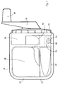
- the cherry pitter 10 shown in the drawings includes an upper portion 12 which supports the pit ejecting mechanism as will be described and this is supported over an open topped bowl 13 which receives the separated pits and cherries.
- the upper portion 12 includes a handle 14 and a rotatable knob 16 at the end of the arm of the handle for operating the pit ejecting mechanism.
- the portion 12 has a downwardly extending rim 19 around its periphery which extends over and encompasses the top edge of the open topped bowl 13. Projecting inwardly from the rim 19 are flanges 19 a and the lower shoulders of these rest on the upper edge 13 a of the bowl 13. Therefore during use the upper portion 12 rests firmly on the bowl 13.
- the portion 12 includes a bowl region 20 into which cherries to be pitted are placed. As best seen in Figures 2, 3 and 4, this region 20 is inclined in a direction towards a passage 22 which is of approximately the width of a typical cherry. In turn this passage 22 is inclined downwardly, as is best seen in Figure 5, so as to feed the cherries to a pitting station 24 (see Figure 1). It is at the pitting station that the cherries are then contacted by an ejector 26 and the pits are removed. Therefore when a number of fresh cherries are placed in the bowl region 20 they will roll gently under gravity across the area 20 into the passage 22 and then down the passage 22 to the station 24. In the passage 22 they will tend to be aligned in a row one behind the other and so will only be received one at a time at the pitting station 24.
- the portion 12 includes an upstanding casing 30 which houses the operating mechanism and supports the handle 16.
- This includes a support block 32 to which the ejector 26 is joined.
- the support block is itself constrained to move up and down an inclined guide 34.
- the ejector 26 is capable of being moved between a retracted position, as shown for example in Figures 2 and 4 where it and the cam member 36 are moved to a top right position in the sense seen in Figure 4, and an advanced ejecting position as shown for example in Figure 3.
- the handle 16 is rotatably supported by means of a cover 40 attached to the casing 30 and the handle 16 is joined on the inside of the cover to a circular rotatable plate 42.
- a cam pin 44 Integrally formed with the circular plate 42 is a cam pin 44. This projects into the slot 38 and can slide from one end to the other end thereof as the handle is rotated. In this way it will move the cam member 36 up and down along the inclined slot 34 as the handle is rotated around a circle.
- the orientation of the pin 44 on the plate 42 is such that, when the pit is being pushed from the flesh of the cherry, ie the hardest part of the operation, the handle is being pushed downwardly.
- the ejector 26 is best shown in Figures 6 and 7. It comprises four arms 50 to 56 which are arranged to radiate out at 90° to one another relative the axis 58 of the ejector. At its pit contacting end each arm has an identical point 60. These points 60 are spaced equally from the axis 58. In addition the ends 62 of each of the arms are inclined so that the end of the ejector is hollowed. In this way the end can engage over the pit of a cherry.
- each of the arms 50 to 54 is identical whilst the arm 56 differs for reasons which will be explained.
- Each arm 50 to 54 includes an initial portion 64 which tapers slightly in a direction towards the tip. It is this portion 64 which initially enters the flesh of the cherry following the tip 60 and cuts the flesh of the cherry. Following the initial portion is a portion 66 of reduced height relative the axis 58. The overall extent of this portion 66 approximates the diameter of a cherry and, because of the smaller size of the arms in this portion 66, there is therefore less contact between the arms and the flesh of the cherry when the ejector is penetrating the cherry and so less chance of damaging the flesh of the cherry. Finally the arms 50 to 54 have at their rear a portion 68 of increased height relative the axis 58 except that this height is still slightly less than the maximum height of the portions 64. The portion 66 and 68 are in turn joined by an inclined portion 70. All of the arms including the arm 56 have a rear end portion 72 which fixes into the block 32 to join the ejector 26 to the latter.
- the arm 56 is of constant height relative the axis 58 the whole way along its length apart from the rear portion 72.
- this arm 56 faces the passage 22. Because it presents a constant flat surface to the incoming cherry it does not trap or mark or cut the skin of the next cherry waiting to arrive at the pitting station as it is retracted from the advance position shown in Figure 3 to the retracted position shown in Figure 2.
- the pitting station 24 is defined at its lower end by means of a wall 80 forming part of the portion 12 and a resilient material flap 82 which, as best shown in Figure 1, includes a cross shaped opening 84 of a shape corresponding to the shape of the ejector 26.
- the arms 50 to 58 cut their way through the flesh of the cherry and also support the cherry as the pit is pushed through the end of the cherry and eventually out through the flesh and through the cross shaped opening in the flap 82.
- the ejector reaches its fully advanced position its tip has penetrated completely through the cherry and also engages into the opening 84 in the flap 82 and so ensures that the pit is fully ejected from the station 24.
- This situation is best shown in Figure 3 where a pit 84 is shown as having been just pushed through the flap 82 from a cherry 86 which is shown with the ejector 26 penetrating fully across it.
- the next cherry 88 is shown in the passage 22.
- the ejector 26 will be withdrawn back to the initial position shown in Figures 2 and 4. Initially the ejector will carry the cherry with it towards the upper most position. However, the cherry will eventually abut against a wall 90 through which the ejector extends. When it does this the wall 90 will prevent further upward movement of the cherry so the ejector will be withdrawn progressively from the cherry. Eventually the pitted cherry will be released and this will drop downwardly. Whilst the cherry is being withdrawn there comes a point where the next cherry 88 ( Figure 3) existing in the passage 22 is able to drop past the now pitted cherry 86 into the station 24.
- the axis of movement of the ejector 26 is inclined according to one aspect of the invention, it is possible to eject the pits in one direction and the pitted cherries in the other direction.
- the bowl 13 on which the upper portion 12 rests will receive the pitted cherries.
- a separate, removable bowl 94 for the pits This is retained in position within the larger bowl 13 by projecting flanges 96.
- the bowl 94 can easily be removed to empty it of accumulated pits and so separate them readily from the pitted cherries at the end of a pitting operation. In that connection the upper portion 12 will of course be first removed from the bowl 13 to obtain access.
Landscapes
- Engineering & Computer Science (AREA)
- Food Science & Technology (AREA)
- Apparatuses For Bulk Treatment Of Fruits And Vegetables And Apparatuses For Preparing Feeds (AREA)
- Confectionery (AREA)
- Food-Manufacturing Devices (AREA)
Applications Claiming Priority (2)
| Application Number | Priority Date | Filing Date | Title |
|---|---|---|---|
| GB919117879A GB9117879D0 (en) | 1991-08-19 | 1991-08-19 | Cherry pitter |
| GB9117879 | 1991-08-19 |
Publications (2)
| Publication Number | Publication Date |
|---|---|
| EP0528628A1 true EP0528628A1 (fr) | 1993-02-24 |
| EP0528628B1 EP0528628B1 (fr) | 1996-10-23 |
Family
ID=10700198
Family Applications (1)
| Application Number | Title | Priority Date | Filing Date |
|---|---|---|---|
| EP92307351A Expired - Lifetime EP0528628B1 (fr) | 1991-08-19 | 1992-08-11 | Dénoyauteur pour cerises |
Country Status (8)
| Country | Link |
|---|---|
| US (1) | US5329843A (fr) |
| EP (1) | EP0528628B1 (fr) |
| CN (1) | CN1037490C (fr) |
| AU (2) | AU658906B2 (fr) |
| CA (1) | CA2075545C (fr) |
| DE (1) | DE69214752T2 (fr) |
| GB (1) | GB9117879D0 (fr) |
| TW (1) | TW213859B (fr) |
Families Citing this family (7)
| Publication number | Priority date | Publication date | Assignee | Title |
|---|---|---|---|---|
| US5619912A (en) * | 1996-04-26 | 1997-04-15 | Ashlock Company, A Division Of Vistan Corporation | Pitting knife drive assembly with box cam and cherry pitting apparatus including same |
| US6289543B1 (en) * | 1999-07-16 | 2001-09-18 | Frans Segers | Process and system for processing cherry pits |
| USD546135S1 (en) | 2004-04-08 | 2007-07-10 | Stephen Howard Ricks | Combination tomato corer and knife |
| US8578845B2 (en) * | 2010-02-02 | 2013-11-12 | Talisman Design, Llc | Cherry pitter having safety and convenience |
| US8196508B2 (en) | 2010-09-21 | 2012-06-12 | Larsen Lawrence J | Continuous fruit pitting by singularization of fruit pieces |
| CN113080474A (zh) * | 2021-05-18 | 2021-07-09 | 王续续 | 一种山楂手工去核设备 |
| USD1057527S1 (en) * | 2024-07-30 | 2025-01-14 | Dan Luo | Cherry separator |
Citations (6)
| Publication number | Priority date | Publication date | Assignee | Title |
|---|---|---|---|---|
| DE146425C (fr) * | ||||
| DE85769C (fr) * | ||||
| CH108037A (fr) * | 1923-01-20 | 1924-12-16 | Plumettaz Emile | Machine à enlever les noyaux de cerises. |
| CH168975A (de) * | 1933-05-27 | 1934-05-15 | Injecta Ag | Früchteentsteiner. |
| US2730149A (en) * | 1952-10-07 | 1956-01-10 | John G Aguilar | Method of pitting fruit |
| FR2452903A1 (fr) * | 1979-04-04 | 1980-10-31 | Baade Kurt | Appareil a denoyauter les quetsches, prunes, cerises |
Family Cites Families (12)
| Publication number | Priority date | Publication date | Assignee | Title |
|---|---|---|---|---|
| US405118A (en) * | 1889-06-11 | Bisch | ||
| US578790A (en) * | 1897-03-16 | Prentice mellen trask | ||
| US1318181A (en) * | 1919-10-07 | Planocfijaph co | ||
| US1047786A (en) * | 1910-07-25 | 1912-12-17 | Leslie S Hackney | Fruit pitter and splitter. |
| US1235706A (en) * | 1917-05-11 | 1917-08-07 | Schroeter Brothers Hardware Company | Cherry-seeder. |
| US2196772A (en) * | 1938-06-09 | 1940-04-09 | S & W Fine Foods Inc | Fruit pitting machinery |
| US2463854A (en) * | 1945-11-02 | 1949-03-08 | Irma M Cowan | Fruit pitter |
| US2552971A (en) * | 1949-02-02 | 1951-05-15 | Smith W Hoover | Cherry pitter |
| US3411556A (en) * | 1966-12-29 | 1968-11-19 | Geo W Ashlock Co | Olive holder for olive pitter |
| US3731615A (en) * | 1970-10-05 | 1973-05-08 | Vistan Corp | Cherry pitter |
| DE3601079A1 (de) * | 1986-01-16 | 1987-07-23 | Leifheit Ag | Geraet zum entsteinen von fruechten |
| ES1000770Y (es) * | 1986-11-11 | 1988-11-01 | Sociedad Anonima De Racionalizacion Y Mecanizacion (Sadrym) | Punzon deshuesador para maquinas deshuesadoras de frutos |
-
1991
- 1991-08-19 GB GB919117879A patent/GB9117879D0/en active Pending
-
1992
- 1992-08-06 TW TW081106238A patent/TW213859B/zh active
- 1992-08-07 CA CA002075545A patent/CA2075545C/fr not_active Expired - Fee Related
- 1992-08-11 US US07/928,514 patent/US5329843A/en not_active Expired - Lifetime
- 1992-08-11 EP EP92307351A patent/EP0528628B1/fr not_active Expired - Lifetime
- 1992-08-11 DE DE69214752T patent/DE69214752T2/de not_active Expired - Fee Related
- 1992-08-18 AU AU21098/92A patent/AU658906B2/en not_active Ceased
- 1992-08-19 CN CN92109419A patent/CN1037490C/zh not_active Expired - Fee Related
-
1995
- 1995-02-01 AU AU11507/95A patent/AU667020B2/en not_active Ceased
Patent Citations (6)
| Publication number | Priority date | Publication date | Assignee | Title |
|---|---|---|---|---|
| DE146425C (fr) * | ||||
| DE85769C (fr) * | ||||
| CH108037A (fr) * | 1923-01-20 | 1924-12-16 | Plumettaz Emile | Machine à enlever les noyaux de cerises. |
| CH168975A (de) * | 1933-05-27 | 1934-05-15 | Injecta Ag | Früchteentsteiner. |
| US2730149A (en) * | 1952-10-07 | 1956-01-10 | John G Aguilar | Method of pitting fruit |
| FR2452903A1 (fr) * | 1979-04-04 | 1980-10-31 | Baade Kurt | Appareil a denoyauter les quetsches, prunes, cerises |
Also Published As
| Publication number | Publication date |
|---|---|
| AU2109892A (en) | 1993-02-25 |
| US5329843A (en) | 1994-07-19 |
| AU667020B2 (en) | 1996-02-29 |
| AU658906B2 (en) | 1995-05-04 |
| DE69214752T2 (de) | 1997-02-20 |
| AU1150795A (en) | 1995-04-27 |
| TW213859B (fr) | 1993-10-01 |
| CA2075545A1 (fr) | 1993-02-20 |
| CA2075545C (fr) | 2003-06-03 |
| CN1037490C (zh) | 1998-02-25 |
| EP0528628B1 (fr) | 1996-10-23 |
| GB9117879D0 (en) | 1991-10-09 |
| CN1070809A (zh) | 1993-04-14 |
| DE69214752D1 (de) | 1996-11-28 |
Similar Documents
| Publication | Publication Date | Title |
|---|---|---|
| EP0400722A2 (fr) | Procédé et installation d'un produit végétal | |
| US4771682A (en) | Peeling machine | |
| KR101184870B1 (ko) | 양파 껍질 제거기 | |
| JP3167028B2 (ja) | 切断アセンブリ | |
| US5410955A (en) | Pear processing method and apparatus | |
| EP0627284A2 (fr) | Appareil pour couper des fruits | |
| US2667118A (en) | Fruit juicer | |
| WO2016030866A1 (fr) | Préparation produire | |
| US4917007A (en) | Juicing apparatus | |
| EP0528628B1 (fr) | Dénoyauteur pour cerises | |
| US5181458A (en) | Apparatus for producing a vegetable product | |
| US6969535B2 (en) | Method for pitting and slicing olives with spring-loaded, adjustable slicing knife assembly | |
| US5199350A (en) | Cutting device | |
| US4545297A (en) | Onion peeling device | |
| EP1251743B1 (fr) | Moyens pour ejecter a distance la lame d'une machine de decouennage de viande | |
| JPS6261302B2 (fr) | ||
| US2753903A (en) | Fruit juicing machine with rind ejector | |
| US3842727A (en) | Fruit slicing apparatus | |
| US4006677A (en) | Peach repitting machine | |
| US1823854A (en) | Fruit paring machine | |
| US20180020713A1 (en) | Fruit flesh extracting machine | |
| US2687156A (en) | Apparatus for removing the hearts from artichokes and method | |
| US2525990A (en) | Feeding and cutting means for citrus fruit juice extractors | |
| US4479425A (en) | Fruit cutter and juicer | |
| US2406736A (en) | Pitting machine |
Legal Events
| Date | Code | Title | Description |
|---|---|---|---|
| PUAI | Public reference made under article 153(3) epc to a published international application that has entered the european phase |
Free format text: ORIGINAL CODE: 0009012 |
|
| AK | Designated contracting states |
Kind code of ref document: A1 Designated state(s): CH DE FR GB IT LI |
|
| 17P | Request for examination filed |
Effective date: 19930818 |
|
| 17Q | First examination report despatched |
Effective date: 19940714 |
|
| GRAH | Despatch of communication of intention to grant a patent |
Free format text: ORIGINAL CODE: EPIDOS IGRA |
|
| GRAH | Despatch of communication of intention to grant a patent |
Free format text: ORIGINAL CODE: EPIDOS IGRA |
|
| GRAA | (expected) grant |
Free format text: ORIGINAL CODE: 0009210 |
|
| AK | Designated contracting states |
Kind code of ref document: B1 Designated state(s): CH DE FR GB IT LI |
|
| PG25 | Lapsed in a contracting state [announced via postgrant information from national office to epo] |
Ref country code: LI Effective date: 19961023 Ref country code: FR Effective date: 19961023 Ref country code: CH Effective date: 19961023 |
|
| REF | Corresponds to: |
Ref document number: 69214752 Country of ref document: DE Date of ref document: 19961128 |
|
| ITF | It: translation for a ep patent filed | ||
| EN | Fr: translation not filed | ||
| REG | Reference to a national code |
Ref country code: CH Ref legal event code: PL |
|
| PLBE | No opposition filed within time limit |
Free format text: ORIGINAL CODE: 0009261 |
|
| STAA | Information on the status of an ep patent application or granted ep patent |
Free format text: STATUS: NO OPPOSITION FILED WITHIN TIME LIMIT |
|
| 26N | No opposition filed | ||
| REG | Reference to a national code |
Ref country code: GB Ref legal event code: IF02 |
|
| PG25 | Lapsed in a contracting state [announced via postgrant information from national office to epo] |
Ref country code: IT Free format text: LAPSE BECAUSE OF NON-PAYMENT OF DUE FEES;WARNING: LAPSES OF ITALIAN PATENTS WITH EFFECTIVE DATE BEFORE 2007 MAY HAVE OCCURRED AT ANY TIME BEFORE 2007. THE CORRECT EFFECTIVE DATE MAY BE DIFFERENT FROM THE ONE RECORDED. Effective date: 20050811 |
|
| PGFP | Annual fee paid to national office [announced via postgrant information from national office to epo] |
Ref country code: DE Payment date: 20080821 Year of fee payment: 17 |
|
| PGFP | Annual fee paid to national office [announced via postgrant information from national office to epo] |
Ref country code: GB Payment date: 20080820 Year of fee payment: 17 |
|
| GBPC | Gb: european patent ceased through non-payment of renewal fee |
Effective date: 20090811 |
|
| PG25 | Lapsed in a contracting state [announced via postgrant information from national office to epo] |
Ref country code: DE Free format text: LAPSE BECAUSE OF NON-PAYMENT OF DUE FEES Effective date: 20100302 |
|
| PG25 | Lapsed in a contracting state [announced via postgrant information from national office to epo] |
Ref country code: GB Free format text: LAPSE BECAUSE OF NON-PAYMENT OF DUE FEES Effective date: 20090811 |