EP0528700A1 - Verstellbare Klemme für Feuerzeughalter - Google Patents
Verstellbare Klemme für Feuerzeughalter Download PDFInfo
- Publication number
- EP0528700A1 EP0528700A1 EP92401356A EP92401356A EP0528700A1 EP 0528700 A1 EP0528700 A1 EP 0528700A1 EP 92401356 A EP92401356 A EP 92401356A EP 92401356 A EP92401356 A EP 92401356A EP 0528700 A1 EP0528700 A1 EP 0528700A1
- Authority
- EP
- European Patent Office
- Prior art keywords
- lighter
- base
- tongue
- clip according
- support
- Prior art date
- Legal status (The legal status is an assumption and is not a legal conclusion. Google has not performed a legal analysis and makes no representation as to the accuracy of the status listed.)
- Withdrawn
Links
- 210000002105 tongue Anatomy 0.000 claims abstract description 71
- 238000007373 indentation Methods 0.000 claims description 9
- 230000002093 peripheral effect Effects 0.000 claims description 5
- 230000000903 blocking effect Effects 0.000 abstract 1
- 235000019504 cigarettes Nutrition 0.000 description 20
- 230000000295 complement effect Effects 0.000 description 3
- 230000000284 resting effect Effects 0.000 description 3
- 210000002445 nipple Anatomy 0.000 description 2
- 230000006978 adaptation Effects 0.000 description 1
- 239000000470 constituent Substances 0.000 description 1
- 230000000694 effects Effects 0.000 description 1
- 239000000463 material Substances 0.000 description 1
- 238000000034 method Methods 0.000 description 1
- 230000002028 premature Effects 0.000 description 1
- 238000003825 pressing Methods 0.000 description 1
- 230000000717 retained effect Effects 0.000 description 1
Images


Classifications
-
- F—MECHANICAL ENGINEERING; LIGHTING; HEATING; WEAPONS; BLASTING
- F23—COMBUSTION APPARATUS; COMBUSTION PROCESSES
- F23Q—IGNITION; EXTINGUISHING-DEVICES
- F23Q2/00—Lighters containing fuel, e.g. for cigarettes
- F23Q2/34—Component parts or accessories
-
- A—HUMAN NECESSITIES
- A24—TOBACCO; CIGARS; CIGARETTES; SIMULATED SMOKING DEVICES; SMOKERS' REQUISITES
- A24F—SMOKERS' REQUISITES; MATCH BOXES; SIMULATED SMOKING DEVICES
- A24F15/00—Receptacles or boxes specially adapted for cigars, cigarettes, simulated smoking devices or cigarettes therefor
- A24F15/12—Receptacles or boxes specially adapted for cigars, cigarettes, simulated smoking devices or cigarettes therefor for pocket use
- A24F15/18—Receptacles or boxes specially adapted for cigars, cigarettes, simulated smoking devices or cigarettes therefor for pocket use combined with other objects
Definitions
- the present invention relates to a lighter clip.
- Various cigarette lighter holders are already on the market today, some of which include a clip to be fixed to the wall of a pack of cigarettes in order to secure the pack of cigarettes and the lighter, thereby facilitating the user search for these two objects which he generally uses simultaneously. This joining also makes it possible to ensure that one of the two objects is never transported without the other.
- lighter clip Such a lighter clip is described in French patent application No. 2,414,688. In this application, the lighter is however not very maintained. Also known, sold under the trade name "Lighter Loc", a lighter holder having a support tab provided with a base for determining the longitudinal position of the lighter. In both cases, nothing is provided on the lighter clip to adapt it to lighters of different dimensions, and there is nothing provided for the lighter clip to adapt to packs of cigarettes of different sizes.
- the present invention provides a lighter clip in which various adjustable elements are provided to adapt both to cigarette packs and to lighters of different dimensions.
- the present invention therefore relates to a lighter clip comprising two pinch tongues of longitudinal lamellar shape and a pinch device connecting elastically the upper ends of the two pinch tabs, one pinch pin being said to be hooked, the other pinch tab being said to be of support and comprising, on the one hand, in its upper part a strapping ring consisting of two arms arranged to hold in longitudinal support against itself the upper part of a lighter of elongated shape, on the other part, in its lower part, a square base to longitudinally block the base of the lighter, characterized in that said base is detachably fixed in height between at least two predetermined positions on said support tongue.
- the lighter will always be supported on the base so that even when pressing firmly on its wheel when lighting the lighter, it will not be necessary to hold it to prevent it from sliding down.
- the fixing of the base on the support tongue is a snap-fastening, which comprises at least two snap-on studs snapping into housings of corresponding shape.
- a lighter clip is a cheap object, usually made of plastic, which lends itself well to snap fastening.
- the pins are three in number and arranged on the base and two sets of three housings are arranged in the support tongue, at a distance of approximately 20 mm from one another; indeed it is preferable that the support tongue does not itself include the pins so that there are no unnecessary roughness on the lighter clip; more the number of three for the nipples, and obviously for the housing, allows a good positioning even assuming that one of the three nipples is broken; as for the distance of 20 mm, it corresponds appreciably to the difference in length which is observed on lighters sold on the market.
- the fixing of the base on the support tongue is obtained by a drawer assembly of the base on the lower end of the support tongue by means of grooves made on the face of the base in contact with the tongue and defined by lateral angles carried by this rear face; advantageously, the returns from the lateral angles, parallel to the rear face of the base, bear on their inner face at least one tooth which cooperates with a plurality of notches formed laterally along the support tongue on its face opposite the attachment tab, the plurality of notches defining the predetermined positions of the base on the support tab.
- the base includes a peripheral outer surface which is substantially flat and slightly set back so as to present a decorative, advertising or other element therein; thus the base which could have had only the shape of a simple square, can become an advertising medium; the surface is slightly recessed to avoid premature wear.
- the base is capped with a box-shaped part which carries the decorative, advertising or other element.
- the lighter clip is characterized by the fact that the support tab has in its lower part at least one transverse breakable pre-cutting groove to remove any excess length by breaking.
- the support tab has in its lower part at least one transverse breakable pre-cutting groove to remove any excess length by breaking.
- the hooking tab the one that slides into the cigarette pack
- the hooking tab can be excessively long compared to the height of the cigarette pack; it is therefore also advantageous to be able to get rid of the excess length by breaking it; one can envisage several pre-cutting grooves, but in practice only one is sufficient.
- the strapping ring is an unclosed ring made up of two elastic arms; provision can be made for each elastic arm of the unclosed strapping pliers to have a ball-shaped protuberance at its end to facilitate its handling when introducing a lighter of different dimensions; indeed the elastic arms must hold the small lighters and therefore they must be wide enough to slide the large lighters there, the ball-shaped outgrowth makes this maneuver easier.
- the strapping ring can be closed, like a belt, to better adapt to the different dimensions of lighters; thus, in this case, the two arms carry, at their end, means for adjustable closure of the strapping ring; the closing means are constituted by a series of indentations carried by one of the arms and cooperating with indentations formed inside a passer-by carries by the other arm when the arm which carries the indentations crosses the passer-by.
- each tongue is provided, internally and in its upper part, with grooves and longitudinal projections facing each other. each other ; thus the wall of the cigarette packet, which has just been slid between the tongues, follows the shapes of these grooves and projections which interpenetrate, so that the packet is held securely in place for good joining of the assembly.
- the two tongues are separable from one another and the clamping device is an elastic snap-in system for elastically assembling, by their upper part, the two tongues; elastic snap-fastening systems between plastic parts are well known today, they make it possible to assemble elements which are also molded separately without problem.
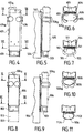
- FIG. 1 a hooking tongue 1, a support tongue 2, and a removable base 3, which, after assembly, constitute a lighter clip. At least the two tongues 1, 2 are made of plastic material having a certain flexibility.
- the latching tongue 1 comprises, in its upper part, a stud 11 and two shoulders 16, 17, as well as grooves and projections 15 longitudinal; the strip 12 of the hooking tongue 1 extends downwards with a thinned part 13 delimited by a transverse pre-cut groove 14.
- the tongue support 2 comprises, in its upper part, a housing 21 provided between two shoulders 16a, 17a; on its face, facing the hooking tongue 1, it has longitudinal grooves and projections 25; on the other face, it comprises two arms 26, 26 a , the ends of which are provided with a protuberance 27, 27 a in the form of a hemisphere; in its lower part, a zone 23 is delimited by a transverse groove 24 for pre-cutting; on either side of this groove 24 are arranged two identical sets of base elements, here the three holes 29 and the three holes 28.
- the base 3 is a small domino of which at least two faces are square l 'One relative to the other, one vertical face, hidden in the figure, has three legs 39, and the other face 32, horizontal and on top, is a support face; the vertical peripheral face 31, which is opposite to that hidden which carries the base elements 39, is shown slightly hollow to be able to accommodate a decorative, advertising, or other element.
- the attachment tab 201 comprises, in its upper part, the end piece 211 and the two shoulders 216, 217; we also see the longitudinal grooves and projections 215; the thinned lower part 213 is delimited by the pre-cut groove 214.
- the support tab 202 comprises, in its upper part, a housing 221 and two shoulders 216 a , 217 a ; the inner face has longitudinal grooves and projections 225; on the opposite face is shown the arm 226 a , the end of which comprises a hemispherical element 227 a ; the lower part 223 of the support tongue 202 is delimited by a pre-cut groove 224; on either side of this groove 224, the support tongue 2 is provided with base elements 229, 228. On the removable base 203, there are the base elements 239 and the peripheral face 231 slightly set back.
- FIG. 3 the method of mounting the lighter clip will be explained; in this figure, the attachment tab is shown twice, a first time partially dashed 301 a during assembly, and a second time in solid line 301 after assembly; for mounting, the end piece 11 of the hooking tab of FIG. 1 is introduced into the housing 21 of the support tab of FIG. 1 to end up in one another 311/321 in FIG.
- the base 303 is here shown assembled with the support tongue 302 on its lower part 323; assembly is carried out by cooperation of the legs already mentioned; the base elements can be small studs, snap-fit into housings provided for this purpose; preferably, the pins are provided on the base, and the housings are provided on the plate so that the assembly does not have unnecessary roughness; in FIG. 3, the length of the two attachment tabs 301 and of support 302 are the same but this is not an obligation; similarly, the precut grooves 314, 324 are shown opposite one another but this is not an obligation.
- the lighter clip, object of the invention is mainly intended for lighters of elongated shape and of oval section which are commonly found today in commerce and of which there are two models: a large one 80 mm high, oval, inscribed in a 25/15 mm rectangle, and a small one 60 mm high and an oval inscribed in a 20/10 mm rectangle; it can also be noted that there are various heights of cigarette packs, the most common of which are 70 and 90 mm; the height difference is therefore 20 mm.
- Figure 5 is a side view of the same large lighter 505 positioned on the support tongue by the base 503 and the arm 526 a ; we also see, partially, a packet of cigarettes 504, the side wall 541 of which is pinched between the two pinching tongues which are found in FIG. 6, which is a view along the cutting plane VI-VI of FIG. 4
- FIG. 6 we see the large lighter 605 sandwiched between the arms 626, 626 a and a packet of cigarettes 604, the side wall of which is slid between the fastening tab 601 and the support tab 602; the cut being made at the height of the longitudinal grooves and protrusions (marks 15 and 25 in FIG. 1); these grooves and projections of complementary shape improve the pinching effect of the wall of the cigarette packet; however for the sake of clarity of the drawing they have not been shown.
- Figure 7 is a sectional view along the plane VII-VII of Figure 4; the large lighter 705 is supported on the base 703, and the wall 741 of the pack of cigarettes 704 is pinched between the latching tab 701 and the support tab 702.
- FIGS. 4, 5, 6 and 7 are an example of the use of the lighter tongs pinching the wall of a large packet of cigarettes and supporting a large lighter; in this case, the base is in the low position, and the two tabs have their initial length, that is to say that the possibilities of pre-cutting provided by the grooves (marks 14 and 24 of FIG. 1) n have not been used.
- Figure 8 is a front view showing a small lighter 806 resting on the base 803 while the operating members 806 a are released upwards; the removable base 803 is here in the high position and the breakable ends of the tongues, whose position 813, 823 is mentioned in dashed, are absent because they were broken at the height of the pre-cut grooves.
- Figure 10 is a view along section XX of Figure 8, that is to say that it is similar to the view of Figure 6, but, this time, with a small lighter 1006 so that the arms 1026, 1026 a are more closed than in FIG. 6; this difference was already visible in Figure 8 by comparison with Figure 4.
- Figure 11 is a sectional view along the plane XI-XI of Figure 8; we see the small lighter 1106 resting on the base 1103, and we note that, advantageously, the external shape 1124 of the base 1103 is similar to the shape of the small lighter so that the packet of cigarettes, clamp lighter holder and small lighter does not present an element unnecessarily in relief.
- the support tongue 1202 has a lower end 1262 whose face intended to be opposite the hooking tongue carries, laterally, two rows of notches 1264, 1264 a , visible in FIGS. 12 and 13.
- the base 1203 is mounted, on the tongue 1202, in the manner of a drawer: for this, the base 1203 carries lateral angles 1261, 1261 a , extending the lateral faces of the base and provided with returns parallel to the rear face of the base, so that grooves 1260, 1260 a are defined, in which the end 1262 of the tongue 1202 takes place by sliding. This sliding is not free; in fact, the interior surface, parallel to the rear face of the base 1203, of the returns 1266, 1266 has a tooth, one of which, 1263 a , is visible in FIG.
- said inner surface of the returns 1266, 1266 a is at a distance from the rear face of the base 1203 equal to the thickness, constant, of the lower end 1262 of the tongue 1202, so that when the base is mounted on the tongue 1202 , the base is retained vertically in one of the positions for which the lug 1263 a is in a groove 1264, 1264 a , the passage from one position to the other being made possible, by exerting a sufficient vertical relative force, by the elasticity of the plastic.
- the lug 1263 has a section in the shape of a right triangle, as visible in FIG.
- the right angle being located at the bottom of the lug, and the notches 1264, 1264 a have an exactly complementary section: thus , the short side of the triangle, section of the lug 1263 a and the notches 1264, 1264 a , is horizontal and the base is well supported vertically by the tongue 1202. Note that the inclined part of this same section facilitates the adjustment in height, in the direction of movement of the base from bottom to top on the tongue.
- the support tongue 1202 is provided with two arms 1206, 1206 a ; at each of their ends, the arms 1206, 1206 a carry adjustable closing means; the arm 1206 carries on its outer face a series of vertical striations (in the position of FIG.
- the arm 1206 has at the end a loop 1250 a for the arm 1250;
- the loop 1250 a has, on one side, a transverse bar 1270 a internally provided with grooves and indentations 1271 a , complementary to the 1250 series of the arm 1206, and, on the other side, two transverse bars 1272 a , 1273 a , providing between them axially a space to the right of which is located the strip 1270 a ; transversely, the bar 1270 a and the bars 1271 a , 1272 a are at a distance equal to the thickness of the arm 1206 and define a space in which the arm 1206 can slide, on condition of exercising, during this sliding movement , sufficient effort so that the indentations 1250 and 1271 a can pass one over the other taking advantage of the elasticity of the plastic; the assembly functions in the manner of an adjustable belt buckle and allows adaptation to any lighter section to maintain it.
- the tongue 1202 has a pre-cut groove 1224 making it possible to detach any excess length 1223; the base 1203 also includes a peripheral outer surface 1231 which is substantially flat and slightly set back so as to present a decorative, advertising or other element therein.
- the support tongue 1202 equipped with its base 1203, is associated with a hooking tongue as previously described, the other constituent elements of the support tongue 1202 being identical to those of the support tabs previously described; this is the reason why they are not detailed about the tongue 1202.
- the decorative element, advertising or other is carried by a plastic part having the general shape of a box covering the five visible faces of the base 3, 203, 303, 403, 503 , 703, 803, 903, 1103, 1203 on which it is elastically mounted; this arrangement makes it possible to increase the presentation surface of the decorative, advertising or other element.
Landscapes
- Engineering & Computer Science (AREA)
- Chemical & Material Sciences (AREA)
- Combustion & Propulsion (AREA)
- Mechanical Engineering (AREA)
- General Engineering & Computer Science (AREA)
- Lighters Containing Fuel (AREA)
Applications Claiming Priority (2)
| Application Number | Priority Date | Filing Date | Title |
|---|---|---|---|
| FR9110400 | 1991-08-19 | ||
| FR9110400A FR2680562B1 (fr) | 1991-08-19 | 1991-08-19 | Pince porte-briquet ajustable. |
Publications (1)
| Publication Number | Publication Date |
|---|---|
| EP0528700A1 true EP0528700A1 (de) | 1993-02-24 |
Family
ID=9416255
Family Applications (1)
| Application Number | Title | Priority Date | Filing Date |
|---|---|---|---|
| EP92401356A Withdrawn EP0528700A1 (de) | 1991-08-19 | 1992-05-19 | Verstellbare Klemme für Feuerzeughalter |
Country Status (2)
| Country | Link |
|---|---|
| EP (1) | EP0528700A1 (de) |
| FR (1) | FR2680562B1 (de) |
Cited By (3)
| Publication number | Priority date | Publication date | Assignee | Title |
|---|---|---|---|---|
| DE29520344U1 (de) * | 1995-12-22 | 1996-02-15 | Tokai Seiki GmbH, 41199 Mönchengladbach | Portabler Aschenbecher |
| GB2330172A (en) * | 1997-10-13 | 1999-04-14 | Terence Peter Bond | Clip for cigarette lighter |
| WO1999065344A1 (de) * | 1998-06-12 | 1999-12-23 | Nicole Keppler | Feuerzeughalter für eine zigarettenschachtel |
Citations (4)
| Publication number | Priority date | Publication date | Assignee | Title |
|---|---|---|---|---|
| FR1316197A (fr) * | 1962-02-26 | 1963-01-25 | Article de fumeurs | |
| US4363432A (en) * | 1980-11-18 | 1982-12-14 | Warthen William H | Cigarette lighter support |
| FR2578030A1 (fr) * | 1985-02-26 | 1986-08-29 | Seval Herve | Dispositif d'agrafage amovible d'un briquet sur un paquet de cigarettes |
| US4852729A (en) * | 1988-03-01 | 1989-08-01 | Conte John R | Cigarette-lighter holder |
-
1991
- 1991-08-19 FR FR9110400A patent/FR2680562B1/fr not_active Expired - Fee Related
-
1992
- 1992-05-19 EP EP92401356A patent/EP0528700A1/de not_active Withdrawn
Patent Citations (4)
| Publication number | Priority date | Publication date | Assignee | Title |
|---|---|---|---|---|
| FR1316197A (fr) * | 1962-02-26 | 1963-01-25 | Article de fumeurs | |
| US4363432A (en) * | 1980-11-18 | 1982-12-14 | Warthen William H | Cigarette lighter support |
| FR2578030A1 (fr) * | 1985-02-26 | 1986-08-29 | Seval Herve | Dispositif d'agrafage amovible d'un briquet sur un paquet de cigarettes |
| US4852729A (en) * | 1988-03-01 | 1989-08-01 | Conte John R | Cigarette-lighter holder |
Cited By (3)
| Publication number | Priority date | Publication date | Assignee | Title |
|---|---|---|---|---|
| DE29520344U1 (de) * | 1995-12-22 | 1996-02-15 | Tokai Seiki GmbH, 41199 Mönchengladbach | Portabler Aschenbecher |
| GB2330172A (en) * | 1997-10-13 | 1999-04-14 | Terence Peter Bond | Clip for cigarette lighter |
| WO1999065344A1 (de) * | 1998-06-12 | 1999-12-23 | Nicole Keppler | Feuerzeughalter für eine zigarettenschachtel |
Also Published As
| Publication number | Publication date |
|---|---|
| FR2680562B1 (fr) | 1993-11-05 |
| FR2680562A1 (fr) | 1993-02-26 |
Similar Documents
| Publication | Publication Date | Title |
|---|---|---|
| EP0847710B1 (de) | Federgelenk für Haarartikel | |
| EP0150046A2 (de) | Armband für Uhren | |
| FR2751863A1 (fr) | Support de clips hemostatiques | |
| FR2460640A1 (fr) | Etui a lunettes | |
| EP0466656A1 (de) | Armbandverschluss | |
| EP0287583B1 (de) | Armbandverschluss | |
| EP0528700A1 (de) | Verstellbare Klemme für Feuerzeughalter | |
| CH667979A5 (en) | Adjustable fastener for bracelet - has curved central plate having groove in which arm of one part slides and locks in notches in groove | |
| EP0115364A2 (de) | Faltverschluss für Armbänder | |
| CH682290A5 (en) | Wrist watch bracelet - has holder between two sections of bracelet on opposite side to watch, designed to hold second instrument or container | |
| FR2680050A1 (fr) | Serre-cable. | |
| FR2536730A1 (fr) | Dispositif pour ramasser un materiau en forme de fil | |
| EP0744088A1 (de) | Elektrische stecker in englischer ausführung | |
| EP0836822B1 (de) | Verpackungs- und Ausstellungsvorrichtung für Schmuckobjekte oder Uhren, sowie darin benutzbares Halte- oder Aufbewahrungselement | |
| EP1875823A1 (de) | Schnallen mit zwei trennbaren Teilen zur Befestigung eines V-Gurts und ihre Benutzung zur Befestigung eines Schutzhelms | |
| EP0113604A1 (de) | Kleiderbügel mit Klemmvorrichtung | |
| FR2704120A1 (fr) | Fermoir dépliant pour bracelet. | |
| MC1028A1 (fr) | Stylo ou objet analogue, à agrafe escamotables | |
| FR2766676A1 (fr) | Articulation a ressort encapsule pour article de chevelure | |
| FR2690486A1 (fr) | Pince à serrage instantané et à ouverture et à force de serrage réglables, et porte-copie équipé d'une telle pince. | |
| EP1183958B1 (de) | Uhrarmbandverschluss | |
| FR2647316A1 (fr) | Boucle pour ceinture ou analogue | |
| EP0784251A1 (de) | Anschlussvorrichtung für ein Uhrarmband | |
| FR2769804A1 (fr) | Dispositif de maintien de cheveux ou d'un ornement de coiffure dans une chevelure | |
| FR2581297A1 (fr) | Mecanisme de pincement pour pince a cheveux |
Legal Events
| Date | Code | Title | Description |
|---|---|---|---|
| PUAI | Public reference made under article 153(3) epc to a published international application that has entered the european phase |
Free format text: ORIGINAL CODE: 0009012 |
|
| AK | Designated contracting states |
Kind code of ref document: A1 Designated state(s): AT BE CH DE DK ES FR GB GR IT LI LU MC NL PT SE |
|
| 17P | Request for examination filed |
Effective date: 19930621 |
|
| STAA | Information on the status of an ep patent application or granted ep patent |
Free format text: STATUS: THE APPLICATION IS DEEMED TO BE WITHDRAWN |
|
| 18D | Application deemed to be withdrawn |
Effective date: 19941201 |