EP0528962B1 - Verfahren zur speicherung von daten welche das leben eines komplexen produkts betreffen - Google Patents
Verfahren zur speicherung von daten welche das leben eines komplexen produkts betreffen Download PDFInfo
- Publication number
- EP0528962B1 EP0528962B1 EP91910222A EP91910222A EP0528962B1 EP 0528962 B1 EP0528962 B1 EP 0528962B1 EP 91910222 A EP91910222 A EP 91910222A EP 91910222 A EP91910222 A EP 91910222A EP 0528962 B1 EP0528962 B1 EP 0528962B1
- Authority
- EP
- European Patent Office
- Prior art keywords
- transponder
- transmitter
- product
- receiver unit
- signals
- Prior art date
- Legal status (The legal status is an assumption and is not a legal conclusion. Google has not performed a legal analysis and makes no representation as to the accuracy of the status listed.)
- Expired - Lifetime
Links
Images
Classifications
-
- G—PHYSICS
- G06—COMPUTING OR CALCULATING; COUNTING
- G06K—GRAPHICAL DATA READING; PRESENTATION OF DATA; RECORD CARRIERS; HANDLING RECORD CARRIERS
- G06K7/00—Methods or arrangements for sensing record carriers, e.g. for reading patterns
- G06K7/10—Methods or arrangements for sensing record carriers, e.g. for reading patterns by electromagnetic radiation, e.g. optical sensing; by corpuscular radiation
- G06K7/10009—Methods or arrangements for sensing record carriers, e.g. for reading patterns by electromagnetic radiation, e.g. optical sensing; by corpuscular radiation sensing by radiation using wavelengths larger than 0.1 mm, e.g. radio-waves or microwaves
- G06K7/10316—Methods or arrangements for sensing record carriers, e.g. for reading patterns by electromagnetic radiation, e.g. optical sensing; by corpuscular radiation sensing by radiation using wavelengths larger than 0.1 mm, e.g. radio-waves or microwaves using at least one antenna particularly designed for interrogating the wireless record carriers
- G06K7/10346—Methods or arrangements for sensing record carriers, e.g. for reading patterns by electromagnetic radiation, e.g. optical sensing; by corpuscular radiation sensing by radiation using wavelengths larger than 0.1 mm, e.g. radio-waves or microwaves using at least one antenna particularly designed for interrogating the wireless record carriers the antenna being of the far field type, e.g. HF types or dipoles
-
- G—PHYSICS
- G06—COMPUTING OR CALCULATING; COUNTING
- G06K—GRAPHICAL DATA READING; PRESENTATION OF DATA; RECORD CARRIERS; HANDLING RECORD CARRIERS
- G06K7/00—Methods or arrangements for sensing record carriers, e.g. for reading patterns
- G06K7/0008—General problems related to the reading of electronic memory record carriers, independent of its reading method, e.g. power transfer
-
- G—PHYSICS
- G06—COMPUTING OR CALCULATING; COUNTING
- G06K—GRAPHICAL DATA READING; PRESENTATION OF DATA; RECORD CARRIERS; HANDLING RECORD CARRIERS
- G06K7/00—Methods or arrangements for sensing record carriers, e.g. for reading patterns
- G06K7/10—Methods or arrangements for sensing record carriers, e.g. for reading patterns by electromagnetic radiation, e.g. optical sensing; by corpuscular radiation
- G06K7/10009—Methods or arrangements for sensing record carriers, e.g. for reading patterns by electromagnetic radiation, e.g. optical sensing; by corpuscular radiation sensing by radiation using wavelengths larger than 0.1 mm, e.g. radio-waves or microwaves
- G06K7/10158—Methods or arrangements for sensing record carriers, e.g. for reading patterns by electromagnetic radiation, e.g. optical sensing; by corpuscular radiation sensing by radiation using wavelengths larger than 0.1 mm, e.g. radio-waves or microwaves methods and means used by the interrogation device for reliably powering the wireless record carriers using an electromagnetic interrogation field
- G06K7/10178—Methods or arrangements for sensing record carriers, e.g. for reading patterns by electromagnetic radiation, e.g. optical sensing; by corpuscular radiation sensing by radiation using wavelengths larger than 0.1 mm, e.g. radio-waves or microwaves methods and means used by the interrogation device for reliably powering the wireless record carriers using an electromagnetic interrogation field including auxiliary means for focusing, repeating or boosting the electromagnetic interrogation field
-
- G—PHYSICS
- G07—CHECKING-DEVICES
- G07C—TIME OR ATTENDANCE REGISTERS; REGISTERING OR INDICATING THE WORKING OF MACHINES; GENERATING RANDOM NUMBERS; VOTING OR LOTTERY APPARATUS; ARRANGEMENTS, SYSTEMS OR APPARATUS FOR CHECKING NOT PROVIDED FOR ELSEWHERE
- G07C5/00—Registering or indicating the working of vehicles
- G07C5/008—Registering or indicating the working of vehicles communicating information to a remotely located station
-
- G—PHYSICS
- G07—CHECKING-DEVICES
- G07C—TIME OR ATTENDANCE REGISTERS; REGISTERING OR INDICATING THE WORKING OF MACHINES; GENERATING RANDOM NUMBERS; VOTING OR LOTTERY APPARATUS; ARRANGEMENTS, SYSTEMS OR APPARATUS FOR CHECKING NOT PROVIDED FOR ELSEWHERE
- G07C9/00—Individual registration on entry or exit
- G07C9/20—Individual registration on entry or exit involving the use of a pass
- G07C9/28—Individual registration on entry or exit involving the use of a pass the pass enabling tracking or indicating presence
Definitions
- the present invention relates to a method of storing data relating to the life or history of complicated products.
- An example of such products are various kinds of automotive vehicle, particularly cars.
- US-A-4,714,925 shows a system where data are collected in a device in a vehicle. Said data can be transmitted to a collecting point. Said device only operates on a finished product, i.e. on an operating vehicle.
- DE-A-37 29 941 shows a control - and monitoring system for vehicles Wich collects information about the vehicles.
- the system can communicate with a transmitter/receiver unit separate from the vehicle.
- the kind of device used in the present invention is a transponder, a registration transmitter or a so-called escort memory.
- a common feature of all devices of this kind is that they are able to communicate with a so-called registration unit wich includes a transmitter/receiver unit. This communication is two-directional, since the registration unit is able to transmit a signal containing information wich is received by the transponder and stored therein. Furthermore, the registration unit can transmit a query signal which is reflected by the transponder while the signal is modulated with a signal corresponding to the information found stored in the transponder. By reflection is meant that the transmitted query signal is received by the transponder and re-transmitted without adding new energy to the signal.
- Such registration transmitter, transponders or escort memories are well known to the art. These units are based on a two-way communication link which utilizes electromagnetic waves in a freguency range of from 100 kHz and up to IR.
- Such registration transmitters have properties which are adapted to different applications, with respect to signal range, memory capacity, data speed, etc.
- the registration transmitter shall be able to pass though varnishing furnaces heated to temperatures of up to 250°C. This requirement is satisfied by providing the registration transmitter with a heat protector, or by supplying the registration transmitter with energy in a cordless fashion from the registration unit and therewith omitting a battery, although the range is much smaller in this case.
- the registration transmitters or escort memories are reused subsequent to having passed through a production line, i.e. are returned to the beginning of the line and fitted to a new product. It is also normal to use different registration transmitters in different sections of a production line.
- the transmitter includes an oscillator and a modulator which is intended for modulating the signal generated by the oscillator in response to the signal on the clock line and data line respectively.
- the modulator is constructed to perform two significant, separate modulation steps which do not coincide in time on the signal generated by the oscillator, and consequently two independent signal channels are formed, of which a first is intended to carry data signals and the other to carry clock signals.
- the demodulator is intended to demodulate a signal which has been modulated by the receiver and received in the aforesaid manner, and is constructed to recreate the aforesaid two signals.
- the demodulator has a clock-line output and a data-line output.
- This patent specification thus teaches a method of separating the data and clock lines, despite using only one single communication signal with the contactless transmission of data.
- this Patent Application SE-A-8902808-8 teaches a method of contactless transmitting information between a transmitter/receiver unit and a transponder, this transmitter/receiver unit including oscillators, transmitting and receiving antennas, a modulator and a detection circuit.
- the transponder includes a transmitter/receiver antenna, a modulator and a detection circuit.
- the above mentioned Patent Application proposes a solution whereby the transmitter/receiver unit is caused to transmit a first and a second carrier wave which have different frequencies (f1, f2) but the same phase; whereby the difference frequency is formed in the transponder; whereby a third signal having the difference frequency (f3) is caused to be divided into a fourth signal having half the difference frequency (f4) ; whereby the fourth signal is caused to modulate the two carrier waves received in the transponder by applying the carrier waves to a diode or the like, so that the received carrier waves are reflected back to the transmitter/receiver unit; whereby the signal received in the transmitter/receiver unit is mixed therein with one of the frequencies of the first or the second carrier waves; and whereby the two sidebands on respective sides of the carrier wave frequency at which said mixing takes place are produced, these sidebands differing from the last mentioned carrier wave frequency by a frequency wich is equal to half the difference frequency (f4), wherein that sideband which has a frequency midway of the carrier wave frequency
- the present invention thus relates to a method for storing the life data of complicated products, the method having the features mentioned in claim 1.
- the present invention relates to a method of storing data concerning the life history of complicated products, primarily different types of automotive vehicle, particularly cars, comprising the contactless transmission of informtion between a transmitter/receiver unit and a transponder.
- the transponder may be of any suitable known kind, and it will therefore be understood that the invention is not limited to the use of dry particular type of transponder.
- the invention is described with reference to its application with cars, although it will be understood that the invention can be applied with all sorts of products that are complicated and with which it may be important to have knowledge of production data in, for instance, the subsequent service of the product concerned.
- examples of such products include household machines, electric apparatus, copying machines, etc.
- the transponder is thus intended to accompany the product during its manufacture and also to accompany the finished product.
- the transmitter/receiver unit includes one or more oscillators, transmitter and receiver antennas, a modulator and a detection circuit.
- the transponder includes a transmitter/receiver antenna, a modulator and a detection circuit.
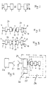
- FIG. 1 is a block schematic of a serial two-wire data bus construted in accordance with the above mentioned Swedish Patent Specification SE-C-459 775, in which there is provided on the "master"-side a transmitter which includes an oscillator 1 which is intended to transmit a signal to a receiver 2 on the "slave"-side in a so-called cordless manner.
- the transmitter includes a modulator 3, to which there is connected a clock line 5 and a data line 4 belonging to the serial bus.
- the modulator is intended to modulate the signal generated by the oscillator, this modulated signal being transmitted.
- the receiver 2 is intended to deliver the received signal to a demodulator 6 which has an output 7 for the clock line 8 of said bus and an output 9 for the data line 10 of said bus.
- the demodulator 6 is intended to recreate the signal content in the clock line 4 and the data line 5 respectively.
- the receiver 2 and the demodulator 6 are included in the transponder, which is also provided with a memory 13, see Figure 4.
- the memory is constructed so that information can be both written into and read from the memory.
- the transponder can be constructed without its own local oscillator, when arranged in accordance with the above mentioned Swedish Patent Application SE-A-8902808-8, where the transmitted clock signal generates an internal frequency.
- the person skilled in this art is fully capable of constructing the transponder in this manner.
- the transponder may also be provided with a local oscillator, in a known manner.
- the frequency generated in the oscillator 1 is comparable with the data speed applied and is therewith in the order of magnitude kHz.
- the aforesaid cordless transmission is effected with the aid of an inductive transmission device, where both the aforesaid transmitter and the aforesaid receiver include a coil 11, 12, see Figure 2.
- Figure 2 illustrates schematically an arrangement according to prior art, in which the oscillator 1 drives an alternating current through the transmitter coil 11, this alternating current being sinusoidal, for example.
- An alternating voltage is generated in the receiver coil 12 by inductance coupling.
- the receiver 2 includes a rectifier bridge and a smoothing capacitor, thereby producing a direct voltage for transponder operation.
- a nonvolatile memory in the transponder i.e. a memory which maintains information without having a voltage applied thereto, no battery is needed in the transponder. This is an important feature, because it enables the transponder to be mounted on the chassis of the car as the car passes through the varnishing ovens, without needing to insulate the transponder to an extent such as to ensure that the transponder will not be heated to a temperature harmful to the battery.
- the transponder is caused to communicate in a contactless fashion with both the transmitter/receiver unit 27 and a transmitter device provided in a vehicle and incorporated in a data network in said vehicle, and in that the data network in the product is made identical to or compatible with the data network used for the contactless transmission between the transmitter/receiver unit and the transponder 24 during the manufacture of the product.
- transponder This affords significant advantages.
- One important advantage is that it enables the transponder to be produced in a simple and inexpensive basic design, wich accompanies the vehicle all the way, where it is unnecessary to interfere with the transponder or the transponder connections in order for the transponder to be able to communicate with, for example, the onboard computer of the vehicle.
- the transponder is attached in some suitable position on the bottom plate of the car at the beginning of the production line. The transponder is not subsequently moved from this position.
- a transmitter device When fitting the electric cables and wires to the car, a transmitter device is fitted and connected through said cables to the onboard computer of the car. This transmitter device is constructed as and corresponds to the trnasmitter/receiver unit 1, 3 - 5, 11.
- the transponter is immediately ready for communication when the transmitter-receiver device is fitted.
- the communication interface at the transponder is inductive. This interface thus lies between the coils 11, 12.
- the range of such inductive transmission will be in the order of 1 meter.
- the communication interface at the transponder 29 is capacitive. This is illustrated in Figure 3, in wich the reference figures as those used in Figure 2 have been used to identify equivalent or corresponding devices.
- a number of electrodes 14-17 are used for transmission, instead of coils. It is also conceivable to combine a capacitive communication interface with coils for transmitting energy to the transponder inductively.
- the range of a capacitive communication interface is in the order of 1 decimeter.
- the transmitter device fitted to the vehicle is caused to transmit and receive signals from the transponder, in the same manner as the transmitter/receiver unit, i.e. inductively or capacitively.
- the transponder may be given a longer range than the aforesaid ranges, by fitting an auxiliary unit temporarily to the transponder.
- the transmitter/receiver unit is therefore caused to communicate by transmitting and receiving signals of microwave frequency, at the same time as the transponder is caused to communicate at its communication interface in the aforesaid manner, i.e. either inductively or capacitively, by means of a transponder auxiliary unit.
- the auxiliary unit is caused to convert received signals of microwave frequency to an inductive or, alternatively, a capacitive signal for transmission to the transponder, and also to convert signals transmitted by the transponder to signals of microwave frequency and to transmit these signals to the transmitter/receiver unit.
- the reference numeral 20 identifies the transmitter/receiver unit with a microwave antenna 21.
- the reference numeral 22 identifies the auxiliary unit with its antenna 23.
- the auxiliary unit may be constructed to include a microwave receiver of known kind which is adapted, in a suitable known manner, to control means intended to control the current in a transmitter coil 11 in accordance with the modulation of the received microwave signal.
- the auxiliary unit is adapted to control a modulator in response to the signal transmitted by the transponder coil 12, in a corresponding manner, such that the transmitted microwave signal is modulated to contain the information as that transmitted by the transponder coil 12.
- the area or section bordered by broken lines in Figure 4 constitutes the transponder 24 in its basic design.
- the transmitter/receiver unit 20 will understand the region 25 defined by chain lines to be a transponder.
- the temporary use of the auxiliary unit 22 temporarily increases the range.
- the auxiliary unit is reused and therefore does not add to the cost of the transponder.
- the transponder 24 can thus be of a very inexpensive and simple basic design.
- the aforesaid auxiliary unit forms an additional memory, by means of which the data storage capacity of the transponder is increased when the transponder 24 coacts with the auxiliary unit 22.
- This additional memory is referenced 26 in Figure 4. This enables the of the transponder 24 to be made smaller and less expensive.
- This additional memory is often necessary during the manufacturing phase of a product, in order to be able to store all of the production data.
- the need of a memory is great on the assembly line.
- the assembly line also has the need of a long-range transponder. There is less need for a memory upstream and downstream of the assembly line.
- the demand placed on transponder range is also less stringent.
- the auxiliary unit has been exemplified by working with microwave frequencies.
- light can be used as the communication means, instead of microwaves.
- the transmitter/receiver unit is caused to communicate by transmitting and receiving light signals, such as infrared light, while the transponder is caused to communicate at its communication interface in the aforesaid manner, i.e. inductively or capacitively, with a transponder auxiliary unit, this auxiliary unit being caused to convert received light signals to an inductive or, alternatively, a capacitive signal for transmission to the transponder, and also to convert signals transmitted by the transponder to light signals and transmit these light signals to the transmitter/receiver unit.
- light signals such as infrared light
Landscapes
- Physics & Mathematics (AREA)
- Engineering & Computer Science (AREA)
- General Physics & Mathematics (AREA)
- Health & Medical Sciences (AREA)
- Electromagnetism (AREA)
- Toxicology (AREA)
- Computer Vision & Pattern Recognition (AREA)
- Theoretical Computer Science (AREA)
- Artificial Intelligence (AREA)
- Computer Networks & Wireless Communication (AREA)
- General Health & Medical Sciences (AREA)
- Arrangements For Transmission Of Measured Signals (AREA)
- Near-Field Transmission Systems (AREA)
- Recording Measured Values (AREA)
- Electrical Discharge Machining, Electrochemical Machining, And Combined Machining (AREA)
- Information Retrieval, Db Structures And Fs Structures Therefor (AREA)
- Radar Systems Or Details Thereof (AREA)
- Time Recorders, Dirve Recorders, Access Control (AREA)
Claims (7)
- Verfahren zum Speicher der Lebensdaten komplexer Gegenstände, hauptsächlich der Lebensdaten unterschiedlicher Arten von selbstfahrenden Fahrzeugen, insbesondere Kraftfahrzeugen, das eine berührungsfreie Übertragung von Information zwischen einer Sender-/Empfängereinheit (27; 28; 20) und einem Transponder (24; 29) umfaßt, wobei die Sender-/Empfängereinheit einen oder mehrere Oszillatoren, Sender- und Empfängerantennen, einen Modulator sowie, eine Detektierschaltung aufweist, und wobei der Transponder eine Sender-/Empfängerantenne, einen Modulator, eine Detektierschaltung sowie einen Speicher (13; 26) aufweist, wobei der Transponder den Gegenstand während seiner Herstellung und ebenso den fertigen Gegenstand begleitet, wobei der Transponder (24; 29) in einer drahtlosen Weise mit der Sender-/Empfängereinheit (27; 28; 20) kommuniziert, dadurch gekennzeichnet, daß der Transponder in einer drahtlosen Weise mit einer Sendereinrichtung kommuniziert, die in dem Gegenstand angeordnet und in ein Datennetz in dem Gegenstand eingefügt ist, daß das Datennetz in dem Gegenstand so ausgelegt ist, daß es identisch zu oder kompatibel mit dem Datennetz ist, das für die berührungsfreie Übertragung zwischen der Sender-/Empfängereinheit (27; 28; 20) und dem Transponder (24; 29) bei der Herstellung des Gegenstands verwendet wird, und daß Lebensdaten während des Gebrauchs des Gegenstands von dem Netz in dem Ggenstand in den Transponder eingespeist und in dem Speicher (13; 26) des Transponders gespeichert werden.
- Verfahren nach Anspruch 1, daduch gekennzeichnet, daß die Kommunikationsschnittstelle an dem Transponder (24) induktiv gebildet wird.
- Verfahren nach Anspruch 1, dadurch gekennzeichnet, daß die Kommunikationsschnittstelle an dem Transponder (29) kapazitiv gebildet wird.
- Verfahren nach Anspruch 2 oder 3, dadurch gekennzeichnet, daß die Sendereinrichtung veranlaßt wird, Signale von dem Transponder (24; 29) in der gleichen Weise wie die Sender-/Empfängereinheit (27; 28) zu senden und zu empfangen, das heißt entweder induktiv oder kapazitiv.
- Verfahren nach Anspruch 1, 2, 3 oder 4, dadurch gekennzeichnet, daß die Sender/Empfängereinheit (20) veranlaßt wird, durch das Senden und Empfangen von Signalen mit Mikrowellenfrequenz zu kommunizieren; und daß ein Transponder (24; 29) veranlaßt wird, an seiner Kommunikationsschnittstelle in einer ähnlichen Weise zu kommunizieren, das heißt entweder induktiv oder kapazitiv, mit der Hilfe einer Unterstützungseinheit (22) für den Transponder, wobei die Unterstützungseinheit (22) veranlaßt wird, empfangene Signale mit Mikrowellenfrequenz in ein induktives oder alternativ ein kapazitives Signal für die Übertragung an den Transponder (24; 29) zu konvertieren, und wobei sie außerdern veranlaßt wird, von dem Transponder (24; 29) übertragene Signale in Signale mit Mikrowellenfrequenz zu konvertieren und die Signale an die Sender-/Empfängereinheit (20) zu senden.
- Verfahren nach Anspruch 1, 2, 3 oder 4, dadurch gekennzeichnet, daß die Sender/Empfängereinheit (20) veranlaßt wird, durch das Senden und Empfangen von Licht-signalen, wie beispielsweise Infrarot-Lichtsignalen, zu kommunizieren, und daß, der Transponder (24; 29) veranlaßt wird, an seiner Kommunikationsschnittstelle induktiv oder kapazitiv mit einer Unterstützungseinheit (22) des Transponders (24; 29) zu kommunizieren, wobei die Unterstützungseinheit (22) veranlaßt wird, empfangene Lichtsignale in ein induktives oder alternativ ein kapazitives Signal für die Übertragung an den Transponder (24; 29) zu konvertieren, und wobei sie außerdem veranlaßt wird, von dem Transponder übertragene Signale in Lichtsignale zu konvertieren und die Signale and die Sender-/Empfängereinheit (20) zu senden.
- Verfahren nach Anspruch 5 oder 6, dadurch gekennzeichnet, daß die Unterstützungseinheit (22) veranlaßt wird, einen zusätzlichen Speicher (26) zu bilden, der derart wirkt, daß die Datenspeicherkapazität des Tranponders (24; 29) gesteigert wird, wenn der Transponder mit der Unterstützungseinheit (22) zusammenwirkt.
Applications Claiming Priority (3)
| Application Number | Priority Date | Filing Date | Title |
|---|---|---|---|
| SE9001729 | 1990-05-14 | ||
| SE9001729A SE500030C2 (sv) | 1990-05-14 | 1990-05-14 | Förfarande för att lagra komplicerade produkters livsdata |
| PCT/SE1991/000341 WO1991018452A1 (en) | 1990-05-14 | 1991-05-14 | A method of storing data relating to the life of a complicated product |
Publications (2)
| Publication Number | Publication Date |
|---|---|
| EP0528962A1 EP0528962A1 (de) | 1993-03-03 |
| EP0528962B1 true EP0528962B1 (de) | 1996-12-11 |
Family
ID=20379473
Family Applications (1)
| Application Number | Title | Priority Date | Filing Date |
|---|---|---|---|
| EP91910222A Expired - Lifetime EP0528962B1 (de) | 1990-05-14 | 1991-05-14 | Verfahren zur speicherung von daten welche das leben eines komplexen produkts betreffen |
Country Status (7)
| Country | Link |
|---|---|
| US (1) | US5379042A (de) |
| EP (1) | EP0528962B1 (de) |
| JP (1) | JPH05507570A (de) |
| AT (1) | ATE146318T1 (de) |
| DE (1) | DE69123576T2 (de) |
| SE (1) | SE500030C2 (de) |
| WO (1) | WO1991018452A1 (de) |
Families Citing this family (21)
| Publication number | Priority date | Publication date | Assignee | Title |
|---|---|---|---|---|
| SE516570C2 (sv) * | 1992-02-14 | 2002-01-29 | Combitech Traffic Syst Ab | System för överföring av information medelst mikrovågor, samt kommunikationsenhet |
| FI94562C (fi) * | 1992-11-09 | 1995-09-25 | Tapio Robertsson | Rullan tunnistuslaite ja menetelmä sen valmistamiseksi |
| DE19507721C2 (de) * | 1995-03-07 | 1997-10-02 | Aeg Identifikationssys Gmbh | Transponderanordnung für elektromagnetische Abfragesysteme |
| US6111524A (en) | 1995-11-09 | 2000-08-29 | Vehicle Enhancement Systems, Inc. | Systems and methods for identifying tractor/trailers and components thereof |
| US7449993B2 (en) * | 1995-11-09 | 2008-11-11 | Vehicle Enhancement Systems, Inc. | System, apparatus and methods for data communication between vehicle and remote data communication terminal, between portions of vehicle and other portions of vehicle, between two or more vehicles, and between vehicle and communications network |
| SE9600015D0 (sv) * | 1996-01-02 | 1996-01-02 | Tagmaster Ab | Anordning och system med trå databärare |
| ZA9710865B (en) * | 1996-12-04 | 1998-06-23 | Frederic Pagnol | A method of monitoring and programming a plurality of transponders simultaneously, and apparatus for implementing the method. |
| US5995898A (en) * | 1996-12-06 | 1999-11-30 | Micron Communication, Inc. | RFID system in communication with vehicle on-board computer |
| DE19848938A1 (de) * | 1998-10-23 | 2000-04-27 | Aeg Identifikationssys Gmbh | Objektidentifikationssystem |
| FI111880B (fi) * | 1999-04-26 | 2003-09-30 | Metso Paper Inc | Menetelmä ja laite paperi-/kartonki- tai sellu- tai jälkikäsittelykoneen erilaisten komponenttien ominaisuuksien ja/tai ympäristöolosuhteiden sekä niissä tapahtuvien muutosten seuraamiseksi ja tallentamiseksi |
| US6320169B1 (en) | 1999-09-07 | 2001-11-20 | Thermal Solutions, Inc. | Method and apparatus for magnetic induction heating using radio frequency identification of object to be heated |
| US6714133B2 (en) * | 1999-12-15 | 2004-03-30 | Koninklijke Philips Electronics N.V. | Short range communication system |
| WO2001045038A2 (en) * | 1999-12-15 | 2001-06-21 | Starlab Nv/Sa | Short range communication system |
| EP1215616A3 (de) * | 2000-12-07 | 2002-10-30 | Valter Mazzarolo | Informative Daten-Identifizierungseinrichtung für Brillen |
| US6953919B2 (en) * | 2003-01-30 | 2005-10-11 | Thermal Solutions, Inc. | RFID-controlled smart range and method of cooking and heating |
| US6970092B2 (en) | 2003-04-15 | 2005-11-29 | Koninklijke Philips Electronics,N.V. | Short range communication system |
| EP1533748A1 (de) * | 2003-11-20 | 2005-05-25 | Steiner AG Weggis | Einrichtung zum elektronischen Aufzeichnen bestimmter Daten, insbesondere für einzelne Funktionseinheiten einer Kaffeemaschine |
| US7573005B2 (en) * | 2004-04-22 | 2009-08-11 | Thermal Solutions, Inc. | Boil detection method and computer program |
| US8643474B2 (en) | 2008-05-05 | 2014-02-04 | Round Rock Research, Llc | Computer with RFID interrogator |
| FR2934941B1 (fr) * | 2008-08-08 | 2010-09-10 | Inside Contactless | Procede et dispositif pour echanger des donnees entre un lecteur a champ h et un dispositif a champ e |
| DE102018201332A1 (de) * | 2018-01-11 | 2019-07-11 | Fraunhofer-Gesellschaft zur Förderung der angewandten Forschung e.V. | Synchronisation in Mehrträger-RFID Systemen |
Family Cites Families (18)
| Publication number | Priority date | Publication date | Assignee | Title |
|---|---|---|---|---|
| DK134666B (da) * | 1970-02-20 | 1976-12-20 | Svejsecentralen | Fremgangsmåde til mærkning og senere lokalisering, identifikation og registrering af fysiske objekter samt elektronisk mærkningsoragn til anvendelse ved udøvelse af fremgangsmåden. |
| US3774205A (en) * | 1971-08-02 | 1973-11-20 | Ncr Co | Merchandise mark sensing system |
| US3832530A (en) * | 1972-01-04 | 1974-08-27 | Westinghouse Electric Corp | Object identifying apparatus |
| SE380220B (sv) * | 1973-11-13 | 1975-11-03 | K O I Olsson | Informationsoverforingsanleggning for tradlos overforing med en fragestation och ett svarsdon |
| SE417026C (sv) * | 1976-09-02 | 1982-05-17 | Inst For Mikrovagsteknik Vid T | Anordning for registrering av en forsta typ av foremal, som ror sig relativt en andra typ av foremal |
| SE413359B (sv) * | 1978-08-25 | 1980-05-19 | Stiftelsen Inst Mikrovags | Anordning for astadkommande av ett enkelt sidband |
| US4937581A (en) * | 1980-02-13 | 1990-06-26 | Eid Electronic Identification Systems Ltd. | Electronic identification system |
| US5164732A (en) * | 1980-02-13 | 1992-11-17 | Eid Electronic Identification Systems Ltd. | Highway vehicle identification system with high gain antenna |
| GB2076259B (en) * | 1980-05-13 | 1984-03-28 | Rodrian James A | Animal identification and estrus detection system |
| US4827395A (en) * | 1983-04-21 | 1989-05-02 | Intelli-Tech Corporation | Manufacturing monitoring and control systems |
| US4912471A (en) * | 1983-11-03 | 1990-03-27 | Mitron Systems Corporation | Interrogator-responder communication system |
| GB8432807D0 (en) * | 1984-12-31 | 1985-02-06 | Emx International Ltd | Loop data link |
| DE3786836T2 (de) * | 1986-05-30 | 1994-01-13 | Sharp Kk | Mikrowellen-Datenübertragungsgerät. |
| DE3729941A1 (de) * | 1987-09-07 | 1989-03-23 | Dopp Hans Joachim | Steuer-, regel- und/oder ueberwachungssystem fuer fahrzeuge, insbesondere landgebundene kraftfahrzeuge |
| JP2612190B2 (ja) * | 1988-08-31 | 1997-05-21 | 山武ハネウエル株式会社 | 応答装置と質問装置からなる全二重通信装置 |
| NO884144L (no) * | 1988-09-16 | 1990-03-19 | Universal Tracking Systems Ltd | Identifikasjonssystem. |
| US5030807A (en) * | 1990-01-16 | 1991-07-09 | Amtech Corporation | System for reading and writing data from and into remote tags |
| US5055659A (en) * | 1990-02-06 | 1991-10-08 | Amtech Technology Corp. | High speed system for reading and writing data from and into remote tags |
-
1990
- 1990-05-14 SE SE9001729A patent/SE500030C2/sv unknown
-
1991
- 1991-05-14 EP EP91910222A patent/EP0528962B1/de not_active Expired - Lifetime
- 1991-05-14 DE DE69123576T patent/DE69123576T2/de not_active Expired - Lifetime
- 1991-05-14 AT AT91910222T patent/ATE146318T1/de not_active IP Right Cessation
- 1991-05-14 JP JP91509623A patent/JPH05507570A/ja active Pending
- 1991-05-14 US US07/941,145 patent/US5379042A/en not_active Expired - Lifetime
- 1991-05-14 WO PCT/SE1991/000341 patent/WO1991018452A1/en not_active Ceased
Also Published As
| Publication number | Publication date |
|---|---|
| DE69123576D1 (de) | 1997-01-23 |
| ATE146318T1 (de) | 1996-12-15 |
| US5379042A (en) | 1995-01-03 |
| EP0528962A1 (de) | 1993-03-03 |
| SE500030C2 (sv) | 1994-03-21 |
| DE69123576T2 (de) | 1997-06-26 |
| SE9001729D0 (sv) | 1990-05-14 |
| WO1991018452A1 (en) | 1991-11-28 |
| JPH05507570A (ja) | 1993-10-28 |
| SE9001729L (sv) | 1991-11-15 |
Similar Documents
| Publication | Publication Date | Title |
|---|---|---|
| US5379042A (en) | Method of storing data relating to the life of a complicated product | |
| US11091052B2 (en) | Wireless charging station device with frequency selection and vehicle position determination | |
| JP3621560B2 (ja) | 電磁誘導型データキャリアシステム | |
| CN100573564C (zh) | 双频段多协议射频识别设备系统 | |
| US7150407B1 (en) | System for interchanging data between at least two contactless data storage media | |
| EP0428322A1 (de) | Funkfernmessystem | |
| US10110019B2 (en) | Battery with communication interface | |
| US9811696B2 (en) | Method for operating a field device of process automation technology | |
| JPH1188241A (ja) | データキャリアシステム | |
| EP1261933B1 (de) | System für den drahtlosen bidirektionalen Transfer elektrischer Signale | |
| US20070176823A1 (en) | Potential Separation for Filling Level Radar | |
| HUP0000897A2 (en) | Method for contactless information and power transmission | |
| EP1933260B1 (de) | System und Verfahren zur RFID-basierten Überwachung | |
| CN101587558A (zh) | 一种有源应答机的重复充电 | |
| KR20000057368A (ko) | 비접촉형 통신시스템 및 그에 사용되는 질문기 | |
| KR102834690B1 (ko) | 액세스 시스템 | |
| US20230283114A1 (en) | Cross talk and interference mitigation in dual wireless power transmitter | |
| CN109245789A (zh) | 将车辆与电子装置耦合的无线耦合装置 | |
| CN119599037A (zh) | 一种实现光交箱中识别端口占用的监控系统 | |
| JP2002507526A (ja) | データ処理装置または通信装置を備えた在庫品目録作成システム | |
| CN218866485U (zh) | 一种rfid读卡模块电路 | |
| JP3862112B2 (ja) | データキャリア | |
| KR101603598B1 (ko) | 철도차량관리용 듀얼밴드 알에프아이디 능동형 태그 | |
| US20090289766A1 (en) | Smartcard and method for the production of a smartcard | |
| JP2561020B2 (ja) | 非接触式データ設定装置およびそれを用いた通信システム |
Legal Events
| Date | Code | Title | Description |
|---|---|---|---|
| PUAI | Public reference made under article 153(3) epc to a published international application that has entered the european phase |
Free format text: ORIGINAL CODE: 0009012 |
|
| 17P | Request for examination filed |
Effective date: 19921117 |
|
| AK | Designated contracting states |
Kind code of ref document: A1 Designated state(s): AT BE CH DE DK ES FR GB GR IT LI LU NL SE |
|
| 17Q | First examination report despatched |
Effective date: 19950213 |
|
| GRAG | Despatch of communication of intention to grant |
Free format text: ORIGINAL CODE: EPIDOS AGRA |
|
| GRAH | Despatch of communication of intention to grant a patent |
Free format text: ORIGINAL CODE: EPIDOS IGRA |
|
| GRAH | Despatch of communication of intention to grant a patent |
Free format text: ORIGINAL CODE: EPIDOS IGRA |
|
| GRAA | (expected) grant |
Free format text: ORIGINAL CODE: 0009210 |
|
| AK | Designated contracting states |
Kind code of ref document: B1 Designated state(s): AT BE CH DE DK ES FR GB GR IT LI LU NL SE |
|
| PG25 | Lapsed in a contracting state [announced via postgrant information from national office to epo] |
Ref country code: IT Free format text: LAPSE BECAUSE OF FAILURE TO SUBMIT A TRANSLATION OF THE DESCRIPTION OR TO PAY THE FEE WITHIN THE PRE;WARNING: LAPSES OF ITALIAN PATENTS WITH EFFECTIVE DATE BEFORE 2007 MAY HAVE OCCURRED AT ANY TIME BEFORE 2007. THE CORRECT EFFECTIVE DATE MAY BE DIFFERENT FROM THE ONE RECORDED.SCRIBED TIME-LIMIT Effective date: 19961211 Ref country code: ES Free format text: THE PATENT HAS BEEN ANNULLED BY A DECISION OF A NATIONAL AUTHORITY Effective date: 19961211 Ref country code: BE Effective date: 19961211 Ref country code: NL Free format text: LAPSE BECAUSE OF FAILURE TO SUBMIT A TRANSLATION OF THE DESCRIPTION OR TO PAY THE FEE WITHIN THE PRESCRIBED TIME-LIMIT Effective date: 19961211 Ref country code: LI Effective date: 19961211 Ref country code: GR Free format text: LAPSE BECAUSE OF FAILURE TO SUBMIT A TRANSLATION OF THE DESCRIPTION OR TO PAY THE FEE WITHIN THE PRESCRIBED TIME-LIMIT Effective date: 19961211 Ref country code: AT Effective date: 19961211 Ref country code: DK Effective date: 19961211 Ref country code: CH Effective date: 19961211 |
|
| REF | Corresponds to: |
Ref document number: 146318 Country of ref document: AT Date of ref document: 19961215 Kind code of ref document: T |
|
| ET | Fr: translation filed | ||
| REF | Corresponds to: |
Ref document number: 69123576 Country of ref document: DE Date of ref document: 19970123 |
|
| PG25 | Lapsed in a contracting state [announced via postgrant information from national office to epo] |
Ref country code: SE Effective date: 19970311 |
|
| NLV1 | Nl: lapsed or annulled due to failure to fulfill the requirements of art. 29p and 29m of the patents act | ||
| PG25 | Lapsed in a contracting state [announced via postgrant information from national office to epo] |
Ref country code: LU Free format text: LAPSE BECAUSE OF NON-PAYMENT OF DUE FEES Effective date: 19970531 |
|
| REG | Reference to a national code |
Ref country code: CH Ref legal event code: PL |
|
| PLBE | No opposition filed within time limit |
Free format text: ORIGINAL CODE: 0009261 |
|
| STAA | Information on the status of an ep patent application or granted ep patent |
Free format text: STATUS: NO OPPOSITION FILED WITHIN TIME LIMIT |
|
| 26N | No opposition filed | ||
| GBPC | Gb: european patent ceased through non-payment of renewal fee |
Effective date: 19970514 |
|
| REG | Reference to a national code |
Ref country code: GB Ref legal event code: 728V |
|
| REG | Reference to a national code |
Ref country code: FR Ref legal event code: ST |
|
| REG | Reference to a national code |
Ref country code: FR Ref legal event code: RN |
|
| REG | Reference to a national code |
Ref country code: GB Ref legal event code: 732E Ref country code: GB Ref legal event code: 728Y |
|
| REG | Reference to a national code |
Ref country code: FR Ref legal event code: FC |
|
| REG | Reference to a national code |
Ref country code: GB Ref legal event code: IF02 |
|
| PGFP | Annual fee paid to national office [announced via postgrant information from national office to epo] |
Ref country code: FR Payment date: 20100622 Year of fee payment: 20 |
|
| PGFP | Annual fee paid to national office [announced via postgrant information from national office to epo] |
Ref country code: DE Payment date: 20100526 Year of fee payment: 20 |
|
| PGFP | Annual fee paid to national office [announced via postgrant information from national office to epo] |
Ref country code: GB Payment date: 20100527 Year of fee payment: 20 |
|
| REG | Reference to a national code |
Ref country code: DE Ref legal event code: R071 Ref document number: 69123576 Country of ref document: DE |
|
| REG | Reference to a national code |
Ref country code: GB Ref legal event code: PE20 Expiry date: 20110513 |
|
| PG25 | Lapsed in a contracting state [announced via postgrant information from national office to epo] |
Ref country code: GB Free format text: LAPSE BECAUSE OF EXPIRATION OF PROTECTION Effective date: 20110513 |
|
| PG25 | Lapsed in a contracting state [announced via postgrant information from national office to epo] |
Ref country code: DE Free format text: LAPSE BECAUSE OF EXPIRATION OF PROTECTION Effective date: 20110514 |