EP0529165A1 - Gurt zum Begrenzen des Ausfederns - Google Patents
Gurt zum Begrenzen des Ausfederns Download PDFInfo
- Publication number
- EP0529165A1 EP0529165A1 EP91309853A EP91309853A EP0529165A1 EP 0529165 A1 EP0529165 A1 EP 0529165A1 EP 91309853 A EP91309853 A EP 91309853A EP 91309853 A EP91309853 A EP 91309853A EP 0529165 A1 EP0529165 A1 EP 0529165A1
- Authority
- EP
- European Patent Office
- Prior art keywords
- suspension system
- strap
- shock absorber
- vehicle
- shock
- Prior art date
- Legal status (The legal status is an assumption and is not a legal conclusion. Google has not performed a legal analysis and makes no representation as to the accuracy of the status listed.)
- Withdrawn
Links
Images


Classifications
-
- B—PERFORMING OPERATIONS; TRANSPORTING
- B60—VEHICLES IN GENERAL
- B60G—VEHICLE SUSPENSION ARRANGEMENTS
- B60G7/00—Pivoted suspension arms; Accessories thereof
- B60G7/04—Buffer means for limiting movement of arms
-
- B—PERFORMING OPERATIONS; TRANSPORTING
- B60—VEHICLES IN GENERAL
- B60G—VEHICLE SUSPENSION ARRANGEMENTS
- B60G2200/00—Indexing codes relating to suspension types
- B60G2200/30—Rigid axle suspensions
- B60G2200/31—Rigid axle suspensions with two trailing arms rigidly connected to the axle
-
- B—PERFORMING OPERATIONS; TRANSPORTING
- B60—VEHICLES IN GENERAL
- B60G—VEHICLE SUSPENSION ARRANGEMENTS
- B60G2202/00—Indexing codes relating to the type of spring, damper or actuator
- B60G2202/10—Type of spring
- B60G2202/15—Fluid spring
- B60G2202/152—Pneumatic spring
-
- B—PERFORMING OPERATIONS; TRANSPORTING
- B60—VEHICLES IN GENERAL
- B60G—VEHICLE SUSPENSION ARRANGEMENTS
- B60G2202/00—Indexing codes relating to the type of spring, damper or actuator
- B60G2202/20—Type of damper
- B60G2202/24—Fluid damper
-
- B—PERFORMING OPERATIONS; TRANSPORTING
- B60—VEHICLES IN GENERAL
- B60G—VEHICLE SUSPENSION ARRANGEMENTS
- B60G2204/00—Indexing codes related to suspensions per se or to auxiliary parts
- B60G2204/10—Mounting of suspension elements
- B60G2204/12—Mounting of springs or dampers
- B60G2204/128—Damper mount on vehicle body or chassis
-
- B—PERFORMING OPERATIONS; TRANSPORTING
- B60—VEHICLES IN GENERAL
- B60G—VEHICLE SUSPENSION ARRANGEMENTS
- B60G2204/00—Indexing codes related to suspensions per se or to auxiliary parts
- B60G2204/10—Mounting of suspension elements
- B60G2204/12—Mounting of springs or dampers
- B60G2204/129—Damper mount on wheel suspension or knuckle
-
- B—PERFORMING OPERATIONS; TRANSPORTING
- B60—VEHICLES IN GENERAL
- B60G—VEHICLE SUSPENSION ARRANGEMENTS
- B60G2204/00—Indexing codes related to suspensions per se or to auxiliary parts
- B60G2204/40—Auxiliary suspension parts; Adjustment of suspensions
- B60G2204/43—Fittings, brackets or knuckles
- B60G2204/4306—Bracket or knuckle for rigid axles, e.g. for clamping
-
- B—PERFORMING OPERATIONS; TRANSPORTING
- B60—VEHICLES IN GENERAL
- B60G—VEHICLE SUSPENSION ARRANGEMENTS
- B60G2204/00—Indexing codes related to suspensions per se or to auxiliary parts
- B60G2204/40—Auxiliary suspension parts; Adjustment of suspensions
- B60G2204/45—Stops limiting travel
- B60G2204/4504—Stops limiting travel using cable or band to prevent extension
Definitions
- This invention relates to suspension systems for wheeled vehicles. More particularly, the present invention relates to an improved device for controlling and restricting travel of the suspension during use.
- All suspension systems for wheeled vehicles are designed to operate within a given range of travel or articulation. As a wheeled vehicle moves over a road or other surface, the wheels continually encounter irregularities in those surfaces that result in forces being transmitted to the vehicle suspension system.
- the vehicle's suspension system therefore, must be able to articulate up and down in the vertical plane from its designed ride height, to accommodate irregularities in the road surface. Although it is important to allow this articulation of the suspension system, it is equally important to provide some type of positive restraint on the maximum amount of allowable travel in both upward and downward directions, to assure that suspension parameters are not exceeded, and thereby prevent any resultant damage to the suspension system components or the vehicle itself.
- Air spring damage may occur, for example, if the stroke of the suspension is not limited and the air spring is overextended. Limitation of downward travel of the suspension system is also particularly important in frameless dump vehicles and vehicles designed to carry materials such as coil steel, wherein a heavy load will be completely removed from the vehicle very quickly.
- Travel of the suspension system in an upward direction has been most commonly restricted by a stop built into the air spring, usually referred to as a "bumper". Travel of the suspension system in a downward direction (also referred to as "rebound") has traditionally been restricted in a variety of different ways.
- the most common method utilizes a hydraulic down stop built into the shock absorbers of the suspension system. Although these systems have the benefit of being simple, they were also somewhat limited, with respect to their ability to restrict articulation of the suspension. In severe applications, the hydraulic stop may not be sufficient to handle the loads imposed on it.
- Yet another object of the present invention is to provide an energy-absorbing strap that can be used alone, or in conjunction with a shock absorber, to restrict downward travel of a vehicle suspension system.
- a vehicle suspension system having a beam, a beam-connecting means between the beam and the vehicle frame, and a continuous energy-absorbing band that restrains vertical movement of the suspension system and may also prevent bottoming-out of a shock absorber associated with the suspension system.
- Figure 1 is a perspective view of one embodiment of the present invention illustrated in conjunction with a vehicle suspension system.
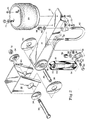
- Figure 2 is an exploded view of the embodiment of the present invention illustrated in Figure 1, in conjunction with a different shock mounting bracket.
- Figure 3 is an exploded perspective view of one embodiment of the present invention, in conjunction with a shock absorber and shock absorber connecting element.
- Figure 4 is a side plan of one embodiment of the present invention, illustrated in conjunction with a vehicle suspension system.
- the present invention is designed to be used in conjunction with a vehicle suspension system.
- Strap 10 of the present invention can be utilized effectively in conjunction with most known mechanical and air suspension systems, to provide resistance against downward or rebound forces.
- the present invention is illustrated in conjunction with a particularly preferred lightweight air suspension system 12 in Figures 1, 2 and 4.
- the structure and operation of the air suspension system illustrated in these drawings is fully described in the co-pending application, also owned by the assignee of the present application: Lightweight Beam Suspension System of Gottschalk et al., Serial No. 578,780, filed September 7, 1990 which incorporates the preferred resilient bushing construction, which is described in detail in U.S. Patent No. 4,166,640 to VanDenberg. If used together as illustrated, the benefits of all three of these inventions can be realized in a single suspension installation. It should be understood, however, as previously stated, that strap 10 of the present invention is not limited in any way in its application to use with this particular suspension system.
- strap 10 is illustrated in combination with suspension system 12, having beam 14 with resilient bushing 16 mounted therein at one end, and flanged member 18 extending along its sides in close proximity to its opposite end.
- the top of beam 14 is connected to air bag 20 using bolts 22 and washers 24.
- the top of air bag 20 is likewise rigidly connected to the frame of vehicle 76 by fastening elements 26.
- Apertured hanger bracket 28 connects the opposite end of beam 14 to vehicle frame 76 by means of nut 30 and bolt 32, with bolt 32 passing through aligned outer washers 34, bracket 28, inner washers 36, and liner 38 within resilient bushing 16.
- Bracket 28 can alternatively be provided with mount 40 for a ride height adjustment mechanism 80, as illustrated in Figures 1 and 4.
- An axle locus is formed by the combination of flange 18, beam 14 and U-shaped member 42 to position and retain axle 68.
- Suspension 12 is also provided with shock absorber 44.
- Shock absorber 44 absorbs energy to prevent suspension oscillation.
- shock absorbers are used alone as rebound stops in some vehicle suspensions. Although many suspensions function satisfactorily without shock absorbers in some environments, an inadequate rebound stop can allow damage to occur to air spring 20 or other components of the suspension.
- Bracket 64 is structurally quite similar to previously described bracket 46. It differs only in that base 66 of bracket 64 does not have an aperture, and is welded to flanged member 18 at a slight distance from nut 56, rather than being attached to member 18 by U-shaped member 42 and nut 56. With bottom of shock absorber 44 secured in bracket 64, strap is also restrained and secured in position looped around shock absorber 44 in the space between bottom end 54 of shock absorber 44 and top surface 66 of bracket 64. This demonstrates the flexibility of strap 10, in that it can be used and secured in position with most shock mounting brackets currently in use without any addition or modification thereto.
- Strap 10 is constructed as a continuous seamless band for structural integrity. Strap 10 must have good energy absorption characteristics to resist downward force of rebound force. To provide proper energy absorption and wear characteristics, strap 10 is constructed of a resilient material. Given the rather harsh environment that strap 10 is exposed to, it is preferred to construct strap 10 of nylon, polyester or another woven polymer. In use, when mounted on suspension system 12, strap 10 is almost always relatively loosely looped around shock absorber 44, except when strong rebound or downward forces are encountered. Shock absorber 44 is under partial compression at rest, and can be further compressed or expanded in reaction to forces encountered. Strap 10 at rest is preferably on the order of about two inches longer than shock absorber 44.
- strap 10 does not act until suspension system 12 moves downward, away from frame 76, and shock absorber 44 is further extended from its initial resting position.
- strap 10 encircles shock absorber 44 and is restrained by the same fasteners that restrain shock absorber 44.
- strap 10 becomes taut and acts to absorb energy and restrict downward travel before shock absorber 44 bottoms out. In this manner, axle travel is restricted and potential damage to air bag 20, or other components of suspension system 12, is prevented.
- strap 10 can be constructed in a variety of different widths, depending upon the desired resistance to forces and materials selected, it has been found that strap widths in the range of one to two inches are preferred. It has also been found that straps 10 can be constructed of a material and size sufficient to withstand up to more than 15,000 pounds of force, with the most preferable constructions being able to withstand forces between 3,000 and 15,000 pounds It should also be understood that the looped construction of strap 10 of the present invention allows a greater magnitude of force to be accommodated than existing devices. Construction of strap 10 presents two flexible bands (one on each side), along the entire length of shock absorber 44, to absorb and counteract rebound forces. Since these forces are acted upon by two bands of strap 10, rather than just one as in prior art devices, each band need only react one-half of the total rebound force, thereby increasing strength and longevity of strap 10 and suspension system 12.
- strap 10 could be used as a rebound stop in a suspension system that does not contain a shock absorber, by mounting strap 10 around existing shock brackets and their fasteners, or using other fastening elements on the beam or axle mount and the frame to secure strap 10. In this manner, strap 10 is used alone as the rebound stop for suspension system 12. Suspension system 12 gains the benefit of the looped endless construction of strap 10 (presenting two bands of flexible resilient material between the frame and the beam to absorb and counteract rebound forces), while eliminating the weight of shock absorber 44 is eliminated. With reference to Figures 1-3, strap 10 used in this configuration would be wrapped around, and, therefore, encircle, bolts 74 and 60 to provide a resilient connection between frame 76 and beam 14.
Landscapes
- Engineering & Computer Science (AREA)
- Mechanical Engineering (AREA)
- Vehicle Body Suspensions (AREA)
- Air Bags (AREA)
Applications Claiming Priority (2)
| Application Number | Priority Date | Filing Date | Title |
|---|---|---|---|
| US07/750,656 US5171036A (en) | 1991-08-27 | 1991-08-27 | Rebound strap |
| US750656 | 1991-08-27 |
Publications (1)
| Publication Number | Publication Date |
|---|---|
| EP0529165A1 true EP0529165A1 (de) | 1993-03-03 |
Family
ID=25018724
Family Applications (1)
| Application Number | Title | Priority Date | Filing Date |
|---|---|---|---|
| EP91309853A Withdrawn EP0529165A1 (de) | 1991-08-27 | 1991-10-24 | Gurt zum Begrenzen des Ausfederns |
Country Status (4)
| Country | Link |
|---|---|
| US (1) | US5171036A (de) |
| EP (1) | EP0529165A1 (de) |
| CA (1) | CA2074056A1 (de) |
| MX (1) | MX9102888A (de) |
Cited By (4)
| Publication number | Priority date | Publication date | Assignee | Title |
|---|---|---|---|---|
| NL1002022C2 (nl) * | 1996-01-04 | 1997-07-07 | Weweler Nv | Luchtveersysteem met beveiliging tegen breuk van de draagarm. |
| WO2006026591A1 (en) * | 2004-08-30 | 2006-03-09 | Behr America, Inc. | Adjustable mounting bracket and method for securing a part in place |
| US8333396B2 (en) | 2010-01-05 | 2012-12-18 | Arvinmeritor Technology, Llc | Top mount trailing arm suspension |
| DE102015209351A1 (de) * | 2015-05-21 | 2016-11-24 | Saf-Holland Gmbh | Längslenker |
Families Citing this family (41)
| Publication number | Priority date | Publication date | Assignee | Title |
|---|---|---|---|---|
| US5328198A (en) * | 1991-04-26 | 1994-07-12 | Adams Andy B | Fluid and tension band-operated hitch adaptor |
| US5667231A (en) * | 1995-09-14 | 1997-09-16 | Dakota Mfg. Co., Inc. | Trailer |
| US5785345A (en) * | 1995-10-16 | 1998-07-28 | The Boler Company | Means for and method of controlling frame rise in vehicle suspensions |
| NZ524252A (en) * | 2000-07-20 | 2004-03-26 | Lauras As | Cox-2 inhibitors for treating HIV and AIDS |
| GB0021718D0 (en) * | 2000-09-05 | 2000-10-18 | Meritor Heavy Vehicle Sys Ltd | Vehicle suspension beam |
| GB0021716D0 (en) * | 2000-09-05 | 2000-10-18 | Meritor Heavy Vehicle Sys Ltd | Vehicle suspension axle wrap |
| US6854749B2 (en) * | 2001-10-31 | 2005-02-15 | International Truck Intellectual Property Company, Llc | Assembly with clamp-force-check-component |
| US7144041B2 (en) * | 2002-07-12 | 2006-12-05 | East Manufacturing Corporation | Aluminum hanger and hanger assembly |
| US6890003B2 (en) * | 2002-07-12 | 2005-05-10 | East Manufacturing Corporation | Suspension subframe assembly |
| US6659479B1 (en) * | 2002-07-18 | 2003-12-09 | Ridewell Corporation | Adjustable suspension hanger assembly |
| US6827360B2 (en) * | 2002-10-24 | 2004-12-07 | Arvinmeritor Technology, Llc | One-piece trailing arm section |
| GB2396140C (en) * | 2002-12-13 | 2011-06-23 | Meritor Heavy Vehicle Sys Ltd | A suspension trailing arm and method of making a suspension trailing arm |
| US7445220B2 (en) | 2004-02-06 | 2008-11-04 | Daimler Trucks North America Llc | Vehicle axle apparatus |
| US8424885B2 (en) | 2005-12-22 | 2013-04-23 | Elliptical Mobile Solutions, LLC | Method and apparatus for an environmentally-protected electronic equipment enclosure |
| US9822923B2 (en) | 2005-04-06 | 2017-11-21 | Suspension Systems Technologies, Llc | Methods and apparatus for a suspension system |
| AU2006242425B2 (en) * | 2005-04-29 | 2010-06-10 | Hendrickson International Corporation | Heavy-duty vehicle axle/suspension system |
| GB0619981D0 (en) * | 2006-10-10 | 2006-11-15 | Meritor Heavy Vehicle Sys Ltd | Suspension sub-assembly |
| US7753391B1 (en) | 2008-04-17 | 2010-07-13 | Automatic Equipment Manufacturing Company | Torsionally-biased, shock-absorbing fifth wheel hitch |
| FR2957555B1 (fr) * | 2010-03-18 | 2012-06-01 | Peugeot Citroen Automobiles Sa | Vehicule comportant un ensemble de liaison positionne entre la structure et l'element de suspension du vehicule, et ensemble de liaison correspondant |
| FR2974540A1 (fr) * | 2011-04-29 | 2012-11-02 | Peugeot Citroen Automobiles Sa | Dispositif de suspension, vehicule et element elastiquement deformable associes |
| US9096108B2 (en) | 2011-05-12 | 2015-08-04 | Vdl Weweler B.V. | Wheel axle suspension |
| US8622406B2 (en) * | 2012-01-13 | 2014-01-07 | Nicholas Eveley | Trailing beam mounting and alignment apparatus |
| CN103057379A (zh) * | 2012-12-29 | 2013-04-24 | 山东美晨科技股份有限公司 | 汽车底盘悬挂限位装置 |
| WO2014113678A1 (en) | 2013-01-17 | 2014-07-24 | Hendrickson Usa, L.L.C. | Mechanical stop for axle/suspension systems |
| US9150072B2 (en) | 2013-11-14 | 2015-10-06 | Hendrickson Usa, L.L.C. | Heavy-duty vehicle axle/suspension system with composite beam |
| FR3026059A1 (fr) * | 2014-09-23 | 2016-03-25 | Peugeot Citroen Automobiles Sa | Amortisseur avec crochets de fixation d'une sangle de montage |
| FR3027083B1 (fr) * | 2014-10-09 | 2016-12-09 | Peugeot Citroen Automobiles Sa | Systeme de protection pour amortisseur hydraulique comportant des decoupes pour une sangle de compression |
| CN107405970B (zh) | 2015-03-20 | 2019-09-06 | 亨德里克森美国有限责任公司 | 车轴/悬架系统的吊架 |
| US9421840B1 (en) * | 2015-05-04 | 2016-08-23 | Motive Power Industry Co., Ltd. | Suspension mechanism |
| US9803715B1 (en) | 2015-09-11 | 2017-10-31 | Robert J. Simmons | Safety strap apparatus to protect a super single truck rim from damage during a tire blowout |
| CA3068073C (en) | 2017-08-16 | 2021-11-16 | Hendrickson Usa, L.L.C. | Axle/suspension system with down stop |
| US10308088B2 (en) | 2017-08-30 | 2019-06-04 | Hendrickson Usa, L.L.C. | Mechanical down-stop for axle/suspension systems |
| EP3678667A4 (de) | 2017-09-08 | 2021-10-20 | Eleszto Genetika, Inc. | Mikroorganismen und verfahren bei der fermentation von benzylisochinolin-alkaloiden |
| WO2019119091A1 (pt) * | 2017-12-20 | 2019-06-27 | Randon S/A Implementos E Participações | Aperfeiçoamento em sistema de fixação para braço de suspensão pneumática |
| FR3077769B1 (fr) * | 2018-02-09 | 2020-01-17 | Psa Automobiles Sa | Amortisseur de suspension de vehicule comprime avec une sangle de maintien et procede de montage associe |
| US11084348B2 (en) | 2018-02-28 | 2021-08-10 | J & J Holdings and Investments, LLC | Clamp, mount tab and tether for limit strap |
| US11173767B2 (en) * | 2019-10-22 | 2021-11-16 | Christopher Cox Creative | Hydraulic anti-roll bar link |
| US11634003B2 (en) | 2020-12-17 | 2023-04-25 | Fox Factory, Inc. | Automated control system for an electronically controlled sway bar link |
| US12502923B2 (en) | 2022-02-23 | 2025-12-23 | Fox Factory, Inc. | Hydraulic cross-linked suspension |
| US12311720B2 (en) | 2022-02-23 | 2025-05-27 | Fox Factory, Inc. | Hydraulic cross-linked suspension |
| US12522042B1 (en) | 2024-10-24 | 2026-01-13 | Fox Factory, Inc. | Linked gas chambers for e-sway disconnect |
Citations (6)
| Publication number | Priority date | Publication date | Assignee | Title |
|---|---|---|---|---|
| FR598814A (fr) * | 1925-05-26 | 1925-12-26 | Amortisseur pour automobiles | |
| US1636386A (en) * | 1924-03-05 | 1927-07-19 | Louie H Oberreich | Cushion rebound check |
| FR875616A (fr) * | 1939-09-15 | 1942-09-29 | A W Kaniss G M B H | Sangle de sécurité en fils métalliques, tresses ou câbles, notamment pour essieux oscillants de véhicules automobiles |
| AT317698B (de) * | 1972-01-20 | 1974-09-10 | Steyr Daimler Puch Ag | Vorrichtung zur begrenzung der abwaertsbewegung von fahrzeug-schwingachsen |
| US4786035A (en) * | 1986-11-21 | 1988-11-22 | The Firestone Tire & Rubber Company | Airspring with internal restraint |
| US4858949A (en) * | 1987-11-20 | 1989-08-22 | Lear Siegler Neway Corp. | Lightweight trailing arm suspension |
Family Cites Families (9)
| Publication number | Priority date | Publication date | Assignee | Title |
|---|---|---|---|---|
| US1579183A (en) * | 1924-01-10 | 1926-03-30 | Weiland Alfred | Shock absorber |
| US2771291A (en) * | 1951-04-10 | 1956-11-20 | Chester H Webb | Elastic cord shock absorber |
| US3228481A (en) * | 1964-04-24 | 1966-01-11 | Bendix Corp | Tie bar bushing |
| US4162090A (en) * | 1978-03-06 | 1979-07-24 | Fruehauf Corporation | Vehicle axle suspension assembly |
| US4166640B1 (en) * | 1978-04-14 | 1994-03-22 | Boler Company Inc | Axle suspension for wheeled vehicles |
| IT1166654B (it) * | 1979-02-23 | 1987-05-06 | Pirelli | Accumulatore di energia |
| US4434721A (en) * | 1982-04-05 | 1984-03-06 | Huey Company | Anti-snap device for drafting board tilting mechanism |
| JPS6177505A (ja) * | 1984-09-26 | 1986-04-21 | Kinugawa Rubber Ind Co Ltd | リバウンドバンパ |
| US5037126A (en) * | 1990-09-07 | 1991-08-06 | The Boler Company | Lightweight beam suspension system |
-
1991
- 1991-08-27 US US07/750,656 patent/US5171036A/en not_active Expired - Lifetime
- 1991-10-24 EP EP91309853A patent/EP0529165A1/de not_active Withdrawn
- 1991-12-31 MX MX9102888A patent/MX9102888A/es unknown
-
1992
- 1992-07-16 CA CA002074056A patent/CA2074056A1/en not_active Abandoned
Patent Citations (6)
| Publication number | Priority date | Publication date | Assignee | Title |
|---|---|---|---|---|
| US1636386A (en) * | 1924-03-05 | 1927-07-19 | Louie H Oberreich | Cushion rebound check |
| FR598814A (fr) * | 1925-05-26 | 1925-12-26 | Amortisseur pour automobiles | |
| FR875616A (fr) * | 1939-09-15 | 1942-09-29 | A W Kaniss G M B H | Sangle de sécurité en fils métalliques, tresses ou câbles, notamment pour essieux oscillants de véhicules automobiles |
| AT317698B (de) * | 1972-01-20 | 1974-09-10 | Steyr Daimler Puch Ag | Vorrichtung zur begrenzung der abwaertsbewegung von fahrzeug-schwingachsen |
| US4786035A (en) * | 1986-11-21 | 1988-11-22 | The Firestone Tire & Rubber Company | Airspring with internal restraint |
| US4858949A (en) * | 1987-11-20 | 1989-08-22 | Lear Siegler Neway Corp. | Lightweight trailing arm suspension |
Cited By (6)
| Publication number | Priority date | Publication date | Assignee | Title |
|---|---|---|---|---|
| NL1002022C2 (nl) * | 1996-01-04 | 1997-07-07 | Weweler Nv | Luchtveersysteem met beveiliging tegen breuk van de draagarm. |
| WO2006026591A1 (en) * | 2004-08-30 | 2006-03-09 | Behr America, Inc. | Adjustable mounting bracket and method for securing a part in place |
| US8210299B2 (en) | 2004-08-30 | 2012-07-03 | Behr America, Inc. | Adjustable mounting bracket and method for securing a part in place |
| US8333396B2 (en) | 2010-01-05 | 2012-12-18 | Arvinmeritor Technology, Llc | Top mount trailing arm suspension |
| DE102015209351A1 (de) * | 2015-05-21 | 2016-11-24 | Saf-Holland Gmbh | Längslenker |
| DE102015209351B4 (de) | 2015-05-21 | 2023-02-02 | Saf-Holland Gmbh | Längslenker |
Also Published As
| Publication number | Publication date |
|---|---|
| US5171036A (en) | 1992-12-15 |
| MX9102888A (es) | 1993-02-01 |
| CA2074056A1 (en) | 1993-02-28 |
Similar Documents
| Publication | Publication Date | Title |
|---|---|---|
| US5171036A (en) | Rebound strap | |
| EP0633852B1 (de) | Dämpfendes und abgefedertes aufhängungssystem | |
| KR101978652B1 (ko) | 와이어로프 마운트 및 유압댐퍼를 이용한 진동저감 장치 | |
| US5109939A (en) | Vibration dampening suspension device for the cab of a truck vehicle | |
| US8807633B2 (en) | Cab suspension system for an off-road vehicle | |
| US6170849B1 (en) | McCall air ride 5th wheel hitch system | |
| CA2144329C (en) | Vibration dampening device | |
| EP2934992B1 (de) | Kabinenfederungssystem für ein arbeitsfahrzeug mit in rundum verlaufenden anschlagpuffern | |
| EP0410680B1 (de) | Verbesserte Vibrationsdampfung und Aufhangungsvorrichtung für eine Lastfahrzeugkabine | |
| EP2868534B1 (de) | Überrollschutzrückhaltesystem für ein Arbeitsfahrzeug | |
| KR101726377B1 (ko) | 자동차용 현가장치 | |
| US5265907A (en) | Auxiliary suspension assembly for Ford "F" and "E" series trucks | |
| US5957231A (en) | Vehicle cab suspension unit | |
| US5785330A (en) | Trailer support wheel assembly | |
| US6725957B2 (en) | Truck cab suspension with lateral locating wheel | |
| US20030111501A1 (en) | ATV load support system | |
| GB2095630A (en) | Vehicle underride protective device | |
| EP0787090A1 (de) | Anordnung für eine elastische aufhängung zwischen fahrerhaus und fahrzeugrahmen | |
| US6193251B1 (en) | Automotive suspension system having a plurality of hydraulic cylinders | |
| EP1957298A1 (de) | Querstabilisator für kraftfahrzeuge | |
| US7798505B2 (en) | Suspension interlock system | |
| US3326544A (en) | Shock absorber for vehicles | |
| US3705742A (en) | Vehicle bumper assembly | |
| KR102253495B1 (ko) | 자동차 서스펜션용 코일스프링장치 | |
| CA1208664A (en) | Vehicle leaf spring suspension |
Legal Events
| Date | Code | Title | Description |
|---|---|---|---|
| PUAI | Public reference made under article 153(3) epc to a published international application that has entered the european phase |
Free format text: ORIGINAL CODE: 0009012 |
|
| AK | Designated contracting states |
Kind code of ref document: A1 Designated state(s): DE ES FR GB IT |
|
| STAA | Information on the status of an ep patent application or granted ep patent |
Free format text: STATUS: THE APPLICATION IS DEEMED TO BE WITHDRAWN |
|
| 18D | Application deemed to be withdrawn |
Effective date: 19930904 |