EP0529232A1 - Gasinjektionsbaustein für das Gasinnendruckspritzen - Google Patents
Gasinjektionsbaustein für das Gasinnendruckspritzen Download PDFInfo
- Publication number
- EP0529232A1 EP0529232A1 EP92110708A EP92110708A EP0529232A1 EP 0529232 A1 EP0529232 A1 EP 0529232A1 EP 92110708 A EP92110708 A EP 92110708A EP 92110708 A EP92110708 A EP 92110708A EP 0529232 A1 EP0529232 A1 EP 0529232A1
- Authority
- EP
- European Patent Office
- Prior art keywords
- gas injection
- feed channel
- gas
- module according
- injection module
- Prior art date
- Legal status (The legal status is an assumption and is not a legal conclusion. Google has not performed a legal analysis and makes no representation as to the accuracy of the status listed.)
- Granted
Links
- 238000002347 injection Methods 0.000 title claims abstract description 39
- 239000007924 injection Substances 0.000 title claims abstract description 39
- 238000001746 injection moulding Methods 0.000 title description 7
- 239000002184 metal Substances 0.000 claims abstract description 5
- 238000007789 sealing Methods 0.000 claims description 17
- 238000005507 spraying Methods 0.000 claims description 5
- 239000011148 porous material Substances 0.000 claims description 3
- 239000004413 injection moulding compound Substances 0.000 abstract description 5
- 150000001875 compounds Chemical class 0.000 abstract 1
- 238000011144 upstream manufacturing Methods 0.000 abstract 1
- 239000007789 gas Substances 0.000 description 27
- 238000007664 blowing Methods 0.000 description 3
- 238000000034 method Methods 0.000 description 3
- 241000589614 Pseudomonas stutzeri Species 0.000 description 2
- 239000000463 material Substances 0.000 description 2
- 230000035515 penetration Effects 0.000 description 2
- 239000007787 solid Substances 0.000 description 2
- 230000001154 acute effect Effects 0.000 description 1
- 230000015572 biosynthetic process Effects 0.000 description 1
- 239000000919 ceramic Substances 0.000 description 1
- 238000001816 cooling Methods 0.000 description 1
- 238000004519 manufacturing process Methods 0.000 description 1
- 230000003014 reinforcing effect Effects 0.000 description 1
- 239000000243 solution Substances 0.000 description 1
- 239000007921 spray Substances 0.000 description 1
Images
Classifications
-
- B—PERFORMING OPERATIONS; TRANSPORTING
- B29—WORKING OF PLASTICS; WORKING OF SUBSTANCES IN A PLASTIC STATE IN GENERAL
- B29C—SHAPING OR JOINING OF PLASTICS; SHAPING OF MATERIAL IN A PLASTIC STATE, NOT OTHERWISE PROVIDED FOR; AFTER-TREATMENT OF THE SHAPED PRODUCTS, e.g. REPAIRING
- B29C45/00—Injection moulding, i.e. forcing the required volume of moulding material through a nozzle into a closed mould; Apparatus therefor
- B29C45/17—Component parts, details or accessories; Auxiliary operations
- B29C45/1703—Introducing an auxiliary fluid into the mould
- B29C45/1734—Nozzles therefor
- B29C45/1736—Nozzles therefor provided with small holes permitting the flow of gas therethrough, e.g. using a porous element of sintered material
Definitions
- the invention relates to a gas injection module for internal gas pressure spraying, in particular pressure-controlled internal gas pressure spraying (airmould method).
- plastic injection molding to make parts of larger cross-section such as reinforcing ribs, handles and the like. Not to spray massively, but to make them hollow by injecting gas during the spraying process. In addition to saving material and weight, this also results in faster cooling and thus a reduction in the cycle time. In addition, the shrinkage problem that often occurs when spraying solid parts can be alleviated.
- the gas e.g. B. nitrogen
- gas injection modules which can be integrated with a plastic injection nozzle or can also be isolated in places on the injection mold, at which cavities are to be produced.
- the invention is intended to remedy this.
- the invention as characterized in the claims, creates a gas injection module in which penetration of injection molding compound cannot occur with certainty. This significantly improves the functional reliability of the injection molding device.
- the gas injection module according to the invention is extremely simple and therefore easy to manufacture, durable and practically maintenance-free. It can easily be designed so that it can also be used to discharge gas at the end of the injection molding process.
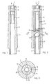
- the gas injection module according to FIG. 1 has an elongated, rotationally symmetrical, slightly conical housing 1 with a threaded extension 2 serving to fasten it, through which a feed channel 3 is guided in the longitudinal direction and ends in an injection opening 4.
- the feed channel 3 it has a sealing plug 5 which is designed as a cylindrical sintered metal plate and which is clamped between an end face of the pipe section 6 facing the injection port 4 as an abutment and a clamping part 7 designed as a grub screw.
- the sealing plug 5 is located immediately behind the injection mouth 4 and is offset from the same only by the thickness of the clamping part 7.
- the pipe section 6 is screwed into the feed channel 3.
- the clamping part 7 also has a hexagonal central opening 8, which can serve as an Allen key seat and permits rapid removal and mounting thereof and replacement of the sealing plug 5.
- sealing plug 5 is impenetrable for materials of higher viscosity, at most a small plug can be formed which fills the opening 8 of the clamping part 7, which plug is however harmless and is thrown away by the gas stream during the next blowing process. By slightly changing the assembly of the sealing plug 5, the formation of a plug could also be completely prevented if necessary.
- the sealing plug 5 could also consist of a ceramic mass instead of sintered metal. It is crucial that it consists of a solid and at the same time porous material, the pore size must be in a range in which the passage of the gas is only slightly obstructed, but penetration of the relatively highly viscous injection molding compound is impossible. Above all, various sintered metal plates, for example those offered by Pressmetall Krebsöge GmbH, Postfach 1250, D-5608 Radevormwald under the product name SIKA-R15, have proven themselves very well.
- the embodiment according to FIGS. 2 and 3 has a largely identical structure to that just described, but has a ball check valve 9 arranged behind the sealing plug 5, which reduces the pressure load on the latter after the blowing phase.
- the end face of the pipe section 6 pointing away from the injection mouth 4 is of inverse conical design and has a plurality of radial grooves 10.
- a second pipe section 11 is also screwed into the feed channel 3, the end face of which facing the first-mentioned pipe section 6 is also inversely conical, but has no grooves, while it forms the thread extension 2 at the opposite end.
- a ball 13 is arranged, the diameter of which is slightly smaller than the inside width of the feed channel 3.
- the ball check valve 9 relieves the sealing plug 5, but makes it impossible for gas to be drawn off by the gas injection module.
- Gas injection modules of the type described can be used at various points in the injection mold, regardless of the plastic injection nozzle.
Landscapes
- Engineering & Computer Science (AREA)
- Manufacturing & Machinery (AREA)
- Mechanical Engineering (AREA)
- Injection Moulding Of Plastics Or The Like (AREA)
- Moulds For Moulding Plastics Or The Like (AREA)
- Percussion Or Vibration Massage (AREA)
Abstract
Description
- Die Erfindung betrifft einen Gasinjektionsbaustein für das Gasinndruckspritzen, insbesondere das druckkontrollierte Gasinnendruckspritzen (Airmould-Verfahren).
- Es ist mehr und mehr üblich, beim Kunststoffspritzgiessen Teile grösseren Querschnitts wie Verstärkungsrippen, Griffe u. dgl. nicht massiv zu spritzen, sondern sie durch Injektion von Gas während des Spritzvorgangs hohl auszubilden. Dadurch wird neben Material- und Gewichtsersparnis auch eine raschere Abkühlung und damit eine Verkürzung der Zykluszeit erreicht. Ausserdem kann das beim Spritzen massiver Teile oft auftretende Problem der Schwindung entschärft werden.
- Das Gas, z. B. Stickstoff, wird mittels Gasinjektionsbausteinen in die Form gepresst, welche mit einer Kunststoffeinspritzdüse integriert oder auch isoliert an Stellen der Spritzgussform angesetzt sein können, an welchen Hohlräume erzeugt werden sollen.
- Es ist bekannt, als Gasinjektionsbaustein ein offenes Rohr zu verwenden (EP-A-0 127 961). Das ist insofern keine zufriedenstellende Lösung, als es sehr leicht zu einem Eindringen von Spritzgussmasse in das Rohr kommt, die dort aushärtet und einen Pfropfen bildet, der die Funktion des Bausteins empfindlich stört oder ganz zum Erliegen bringt. Das Problem ist besonders akut, wenn der Gasinjektionsbaustein auch zur Ableitung des Gases beim Druckabbau am Ende des Spritzgiessens dient.
- Hier soll die Erfindung Abhilfe schaffen. Die Erfindung, wie sie in den Ansprüchen gekennzeichnet ist, schafft einen Gasinjektionsbaustein, bei welchem ein Eindringen von Spritzgussmasse mit Sicherheit nicht auftreten kann. Dadurch wird die Funktionssicherheit der Spritzgussvorrichtung wesentlich verbessert.
- Dieser Vorteil wird gemäss der Erfindung erreicht, ohne dass der Einsatz beweglicher Teile nötig wäre und ohne dass steuerungsbedürftige Schaltvorgänge während des Spritzgiessens erforderlich wären. Der erfindungsgemässe Gasinjektionsbaustein ist äusserst einfach aufgebaut und daher leicht herzustellen, dauerhaft und praktisch wartungsfrei. Er kann ohne weiteres so ausgeführt werden, dass er problemlos auch zum Ableiten von Gas am Ende des Spritzgussvorgangs eingesetzt werden kann.
- Im folgenden wird die Erfindung anhand von nur Ausführungsbeispiele darstellenden Zeichnungen näher erläutert. Es zeigen
- Fig. 1
- ein erste Ausführung eines erfindungsgemässen Gasinjektionsbausteins im Längsschnitt,
- Fig. 2
- eine zweite Ausführung eines erfindungsgemässen Gasinjektionsbaustein im Längsschnitt und
- Fig. 3
- vergrössert einen Querschnitt längs III - III in Fig. 2.
- Der Gasinjektionsbaustein nach Fig. 1 weist ein längliches, rotationssymmetrisches, leicht konisches Gehäuse 1 mit einem seiner Befestigung dienenden Gewindefortsatz 2 auf, durch welches in Längsrichtung ein Zuführkanal 3 geführt ist, welcher in einer Injektionsmündung 4 endet.
- Im Zuführkanal 3 weist er einen als zylindrisches Sintermetallplättchen ausgebildeten Verschlussstopfen 5 auf, welcher zwischen eine der Injektionsmündung 4 zugewandte Stirnfläche eines Rohrstücks 6 als Widerlager und einem als Madenschraube ausgebildeten Klemmteil 7 festgeklemmt ist. Der Verschlussstopfen 5 liegt unmittelbar hinter der Injektionsmündung 4 und ist von derselben nur um die Dicke des Klemmteils 7 abgesetzt. Das Rohrstück 6 ist in den Zuführkanal 3 eingeschraubt. Es weist an seinem dem Verschlussstopfen 5 zugewandten Ende einen Abschnitt auf, an welchem seine Innenwand sechskantig ausgebildet ist, sodass er zwecks leichterer Montage und Entfernung als Inbusschlüsselsitz dienen kann.
- Aehnlich weist auch das Klemmteil 7 eine sechskantige zentrale Oeffnung 8 auf, welche als Inbusschlüsselsitz dienen kann und ein rasches Entfernen und Montieren desselben und Auswechseln des Verschlussstopfens 5 erlaubt.
- Beim Spritzgiessen wird nun nach Beginn der Kunststoffeinspritzung durch den Zuführkanal 3, das Rohrstück 6, den gasdurchlässigen Verschlussstopfen 5 und die Oeffnung 8 im Klemmteil 7 z. B. Stickstoff unter einem Blasdruck von beispielsweise 80 at während 2,5 sec in die Form eingeblasen, dann der Druck auf einen Haltedruck von beispielsweise 50 at reduziert, einige Sekunden lang gehalten und dann langsam entspannt. Die Ableitung von Gas zur Druckreduzierung kann durch den Gasinjektionsbaustein erfolgen.
- Nach dem Ende der Gasinjektion kann es sehr leicht zu einem Eindringen von Spritzgussmasse in die Injektionsmündung 4 kommen. Da jedoch der Verschlussstopfen 5 für Materialien höherer Viskosität undurchdringlich ist, kann es höchstens zur Bildung eines kleinen, die Oeffnung 8 des Klemmteils 7 ausfüllenden Pfropfens kommen, der jedoch unschädlich ist und beim nächsten Blasvorgang durch den Gasstrom weggeschleudert wird. Durch geringfügige Aenderung der Montage des Verschlussstopfens 5 könnte Pfropfenbildung falls nötig auch völlig verhindert werden.
- Der Verschlussstopfen 5 könnte statt aus Sintermetall etwa auch aus einer keramischen Masse bestehen. Entscheidend ist, dass er aus festem und zugleich porösem Material besteht, wobei die Porengrösse in einem Bereich liegen muss, bei welchem der Durchgang des Gases nur wenig behindert wird, jedoch ein Eindringen der relativ hochviskosen Spritzgussmasse ausgeschlossen ist. Vor allem verschiedene Sintermetallplättchen, beispielsweise die von der Firma Pressmetall Krebsöge GmbH, Postfach 1250, D-5608 Radevormwald unter dem Produktnamen SIKA-R15 angebotenen, haben sich sehr gut bewährt.
- Die Ausführung nach Fig. 2 und 3 ist weitgehend gleichartig aufgebaut wie die eben beschriebene, weist jedoch ein hinter dem Verschlussstopfen 5 angeordnetes Kugelrückschlagventil 9 auf, welches die Druckbelastung desselben nach der Blasphase reduziert. Die von der Injektionsmündung 4 wegweisende Stirnfläche des Rohrstücks 6 ist invers konisch ausgebildet und weist mehrere radiale Nuten 10 auf. Demselben mit Abstand gegenüberliegend ist ein zweites Rohrstück 11 ebenfalls in den Zuführkanal 3 eingeschraubt, dessen gegen das erstgenannte Rohrstück 6 weisende Stirnfläche ebenfalls invers konisch ausgebildet ist, jedoch keine Nuten aufweist, während es am entgegengesetzten Ende den Gewindefortsatz 2 bildet. In einer zwischen den beiden Rohrstücken 6 und 11 gebildeten Ventilkammer 12 ist eine Kugel 13 angeordnet, deren Durchmesser etwas geringer ist als die lichte Weite des Zuführkanals 3.
- Strömt nun Gas durch den Zuführkanal 3 zur Injektionsmündung 4, so wird die Kugel 13 gegen die Stirnfläche des Rohrstücks 6 gepresst, sodass Gasströmung seitlich an der Kugel 13 vorbei und durch die Nuten 10 möglich ist. Bei Gasströmung in umgekehrter Richtung wird dagegen die Kugel 13, wie in Fig. 2 dargestellt, gegen die Stirnfläche des Rohrstücks 11 gepresst, auf der sie satt aufliegt, sodas sie dort den Zuführkanal 3 verschliesst und weitere Gasströmung unterbunden ist.
- Das Kugelrückschlagventil 9 entlastet, wie gesagt, den Verschlussstopfen 5, verunmöglicht aber ein Abziehen von Gas durch den Gasinjektionsbaustein.
- Gasinjektionsbausteine der beschriebenen Art können an verschiedenen Stellen der Spritzgussform eingesetzt werden, unabhängig von der Kunststoffeinspritzdüse.
Claims (10)
- Gasinjektionsbaustein für das Gasinnendruckspritzen, mit einem Gehäuse (1), durch welches ein in einer Injektionsmündung (4) endender Zuführkanal (3) geführt ist, dadurch gekennzeichnet, dass der Zuführkanal (4) durch einen Verschlussstopfen (5) aus porösem Material verschlossen ist.
- Gasinjektionsbaustein nach Anspruch 1, dadurch gekennzeichnet, dass der Verschlussstopfen (5) unmittelbar hinter der Injektionsmündung (4) angeordnet ist.
- Gasinjektionsbaustein nach Anspruch 1 oder 2, dadurch gekennzeichnet, dass der Verschlussstopfen (5) die Form eines Plättchens hat.
- Gasinjektionsbaustein nach einem der Ansprüche 1 bis 3, dadurch gekennzeichnet, dass der Verschlussstopfen (5) aus Sintermetall besteht.
- Gasinjektionsbaustein nach einem der Ansprüche 1 bis 4, dadurch gekennzeichnet, dass der Verschlussstopfen (5) zwischen ein im Zuführkanal (3) angeordnetes Auflager und ein von der Injektionsmündung (4) her in denselben einschraubbares Klemmteil (7) mit durchgehender Oeffnung (8) geklemmt ist.
- Gasinjektionsbaustein nach Anspruch 5, dadurch gekennzeichnet, dass die Oeffnung (8) zentral angeordnet und als Inbusschlüsselsitz ausgebildet ist.
- Gasinjektionsbaustein nach Anspruch 5 oder 6, dadurch gekennzeichnet, dass das Auflager durch eine Stirnfläche eines in den Zuführkanal (3) eingeschraubten Rohrstücks (6) gebildet wird.
- Gasinjektionsbaustein nach Anspruch 7, dadurch gekennzeichnet, dass mindestens ein an den Verschlussstopfen (5) anschliessender Abschnitt des Rohrstücks (6) als Inbusschlüsselsitz ausgebildet ist.
- Gasinjektionsbaustein nach einem der Ansprüche 1 bis 8, dadurch gekennzeichnet, dass hinter dem Verschlussstopfen (5) in den Zuführkanal (3) ein Rückschlagventil eingebaut ist.
- Gasinjektionsbaustein nach Anspruch 9, dadurch gekennzeichnet, dass das Rückschlagventil als Kugelrückschlagventil (9) ausgebildet ist.
Applications Claiming Priority (2)
| Application Number | Priority Date | Filing Date | Title |
|---|---|---|---|
| CH2536/91 | 1991-08-29 | ||
| CH2536/91A CH683976A5 (de) | 1991-08-29 | 1991-08-29 | Gasinjektionsbaustein für das Gasinnendruckspritzen. |
Publications (2)
| Publication Number | Publication Date |
|---|---|
| EP0529232A1 true EP0529232A1 (de) | 1993-03-03 |
| EP0529232B1 EP0529232B1 (de) | 1995-12-20 |
Family
ID=4236012
Family Applications (1)
| Application Number | Title | Priority Date | Filing Date |
|---|---|---|---|
| EP92110708A Expired - Lifetime EP0529232B1 (de) | 1991-08-29 | 1992-06-25 | Gasinjektionsbaustein für das Gasinnendruckspritzen |
Country Status (4)
| Country | Link |
|---|---|
| EP (1) | EP0529232B1 (de) |
| AT (1) | ATE131768T1 (de) |
| CH (1) | CH683976A5 (de) |
| DE (1) | DE59204736D1 (de) |
Cited By (3)
| Publication number | Priority date | Publication date | Assignee | Title |
|---|---|---|---|---|
| EP0614742A1 (de) * | 1993-03-05 | 1994-09-14 | Mitsubishi Gas Chemical Company, Inc. | Gaszufuhrdüse |
| EP0640456A1 (de) * | 1992-05-07 | 1995-03-01 | CASCADE ENGINEERING, Inc. | Durch Gas unterstütztes Spritzgiessen |
| WO1999047333A1 (en) * | 1998-03-18 | 1999-09-23 | Winget Larry J | MOLD FOR USE IN A GAS-ASSISTED INJECTION MOlDING SYSTEM AND GAS PIN ASSEMBLY FOR USE THEREIN |
Citations (7)
| Publication number | Priority date | Publication date | Assignee | Title |
|---|---|---|---|---|
| US4164523A (en) * | 1976-09-09 | 1979-08-14 | Robert Hanning | Method of injection-molding and cooling of shaped synthetic-resin bodies |
| US4740150A (en) * | 1987-03-16 | 1988-04-26 | Peerless Cinpres Limited | Injection moulding apparatus |
| WO1990006220A1 (en) * | 1988-12-05 | 1990-06-14 | Carroll Robert E | Injection mold method and apparatus |
| EP0385175A2 (de) * | 1989-02-28 | 1990-09-05 | Mold-Masters Limited | Spritzgusseinrichtung mit Gasdurchfluss durch die Ventilöffnung |
| EP0405663A1 (de) * | 1989-06-26 | 1991-01-02 | Stork Plastics Machinery B.V. | Spritzgiesskopf |
| EP0448283A2 (de) * | 1990-03-14 | 1991-09-25 | Nitrojection Corporation | Angiessbuchse und Düse zum Spritzgiessen |
| EP0485726A2 (de) * | 1990-11-15 | 1992-05-20 | Möller Werke GmbH | Düse zum Injizieren von Gas in die Kavität eines Kunststoffformwerkzeugs, insbesondere einer Spritzgussform |
Family Cites Families (2)
| Publication number | Priority date | Publication date | Assignee | Title |
|---|---|---|---|---|
| JPS608029A (ja) * | 1983-06-28 | 1985-01-16 | Ichikoh Ind Ltd | 合成樹脂成形品の射出成形法及び射出成形装置 |
| JPH0195007A (ja) * | 1987-10-08 | 1989-04-13 | Honda Motor Co Ltd | 樹脂成形品のボス部の成形方法 |
-
1991
- 1991-08-29 CH CH2536/91A patent/CH683976A5/de not_active IP Right Cessation
-
1992
- 1992-06-25 DE DE59204736T patent/DE59204736D1/de not_active Expired - Fee Related
- 1992-06-25 AT AT92110708T patent/ATE131768T1/de not_active IP Right Cessation
- 1992-06-25 EP EP92110708A patent/EP0529232B1/de not_active Expired - Lifetime
Patent Citations (8)
| Publication number | Priority date | Publication date | Assignee | Title |
|---|---|---|---|---|
| US4164523A (en) * | 1976-09-09 | 1979-08-14 | Robert Hanning | Method of injection-molding and cooling of shaped synthetic-resin bodies |
| US4740150A (en) * | 1987-03-16 | 1988-04-26 | Peerless Cinpres Limited | Injection moulding apparatus |
| US4740150B1 (en) * | 1987-03-16 | 1995-07-25 | Peerless Cinpres Ltd | Injection moulding apparatus |
| WO1990006220A1 (en) * | 1988-12-05 | 1990-06-14 | Carroll Robert E | Injection mold method and apparatus |
| EP0385175A2 (de) * | 1989-02-28 | 1990-09-05 | Mold-Masters Limited | Spritzgusseinrichtung mit Gasdurchfluss durch die Ventilöffnung |
| EP0405663A1 (de) * | 1989-06-26 | 1991-01-02 | Stork Plastics Machinery B.V. | Spritzgiesskopf |
| EP0448283A2 (de) * | 1990-03-14 | 1991-09-25 | Nitrojection Corporation | Angiessbuchse und Düse zum Spritzgiessen |
| EP0485726A2 (de) * | 1990-11-15 | 1992-05-20 | Möller Werke GmbH | Düse zum Injizieren von Gas in die Kavität eines Kunststoffformwerkzeugs, insbesondere einer Spritzgussform |
Non-Patent Citations (3)
| Title |
|---|
| PATENT ABSTRACTS OF JAPAN vol. 004, no. 125 (M-030)3. September 1980 & JP-A-55 082 626 ( ASAHI CHEM. IND. CO. ) * |
| PATENT ABSTRACTS OF JAPAN vol. 13, no. 305 (M-849)(3653) 13. Juli 1989 & JP-A-01 095 007 ( HONDA MOTOR ) * |
| PATENT ABSTRACTS OF JAPAN vol. 9, no. 121 (M-382)(1844) 25. Mai 1985 & JP-A-60 008 029 ( ICHIKO KOGYO ) * |
Cited By (4)
| Publication number | Priority date | Publication date | Assignee | Title |
|---|---|---|---|---|
| EP0640456A1 (de) * | 1992-05-07 | 1995-03-01 | CASCADE ENGINEERING, Inc. | Durch Gas unterstütztes Spritzgiessen |
| EP0614742A1 (de) * | 1993-03-05 | 1994-09-14 | Mitsubishi Gas Chemical Company, Inc. | Gaszufuhrdüse |
| US5465908A (en) * | 1993-03-05 | 1995-11-14 | Mitsubishi Gas Chemical Company, Inc. | Gas-feeding nozzle |
| WO1999047333A1 (en) * | 1998-03-18 | 1999-09-23 | Winget Larry J | MOLD FOR USE IN A GAS-ASSISTED INJECTION MOlDING SYSTEM AND GAS PIN ASSEMBLY FOR USE THEREIN |
Also Published As
| Publication number | Publication date |
|---|---|
| CH683976A5 (de) | 1994-06-30 |
| DE59204736D1 (de) | 1996-02-01 |
| ATE131768T1 (de) | 1996-01-15 |
| EP0529232B1 (de) | 1995-12-20 |
Similar Documents
| Publication | Publication Date | Title |
|---|---|---|
| AT395555B (de) | Vorrichtung zum spritzgiessen von hohlraeume enthaltenden gegenstaenden aus kunststoff | |
| DE3884869T2 (de) | Vorrichtung und Verfahren zum Spritzgiessen von thermoplastischen Kunststoffen. | |
| DE69311336T2 (de) | Durch Gas unterstütztes Spritzgiessen | |
| DE69228683T2 (de) | Düse für gasunterstütztes spritzgiessen | |
| DE3819305C2 (de) | ||
| DE19543631C2 (de) | Verfahren und Vorrichtung zum Texturieren | |
| DE3203762A1 (de) | Rueckstroemsperre | |
| DE3203724A1 (de) | Rueckstroemsperre | |
| DE202008017846U1 (de) | Trennmittelsprühvorrichtung für eine Gießmaschine | |
| AT402485B (de) | Spritzkopf zum spritzgiessen von kunststoff nach dem injektionsverfahren | |
| DE4036412A1 (de) | Duese zum injizieren von gas in die kavitaet eines kunststofformwerkzeugs, insbesondere einer spritzgussform | |
| EP0529232B1 (de) | Gasinjektionsbaustein für das Gasinnendruckspritzen | |
| WO2000012285A1 (de) | Verfahren und vorrichtung zum spritzgiess en einer kunststoffmasse | |
| WO1994007675A1 (de) | Vorrichtung zum spritzgiessen von hohlräume enthaltenden gegenständen aus kunststoff sowie verfahren zum betrieb derselben | |
| DE1804640C2 (de) | Spritzkopf zur Herstellung von Kunststoffrohren oder -schläuchen | |
| DE4415506C2 (de) | Heißkanaldüse mit vermindertem Restanguß für Kunststoffspritzgußmaschinen | |
| EP1034848A2 (de) | Kartuschenpresse mit einer Katuschenhalterung | |
| DE3718347A1 (de) | Strangregulator | |
| DE1675562A1 (de) | Verfahren und Vorrichtung zur Regelung eines Fluiddurchsatzes durch Zufuehrung einer Hilfsfluidmenge,insbesondere bei Einspritzduesen | |
| DE20019722U1 (de) | Befestigungsvorrichtung | |
| DE3703181A1 (de) | Spritzduese | |
| EP0910445A1 (de) | Flüssigkeitsverteiler für eine stoffaustauschkolonne | |
| DE2805117A1 (de) | Vorrichtung zum herstellen von formteilen aus kunststoff oder gummi | |
| CH491737A (de) | Spritzkopf für die Erzeugung von rohrförmigen Vorformlingen | |
| AT2044U1 (de) | Möbelbeschlag |
Legal Events
| Date | Code | Title | Description |
|---|---|---|---|
| PUAI | Public reference made under article 153(3) epc to a published international application that has entered the european phase |
Free format text: ORIGINAL CODE: 0009012 |
|
| AK | Designated contracting states |
Kind code of ref document: A1 Designated state(s): AT BE CH DE DK ES FR GB GR IT LI LU MC NL PT SE |
|
| 17P | Request for examination filed |
Effective date: 19930512 |
|
| 17Q | First examination report despatched |
Effective date: 19940630 |
|
| GRAA | (expected) grant |
Free format text: ORIGINAL CODE: 0009210 |
|
| AK | Designated contracting states |
Kind code of ref document: B1 Designated state(s): AT BE CH DE DK ES FR GB GR IT LI LU MC NL PT SE |
|
| PG25 | Lapsed in a contracting state [announced via postgrant information from national office to epo] |
Ref country code: IT Free format text: LAPSE BECAUSE OF FAILURE TO SUBMIT A TRANSLATION OF THE DESCRIPTION OR TO PAY THE FEE WITHIN THE PRE;WARNING: LAPSES OF ITALIAN PATENTS WITH EFFECTIVE DATE BEFORE 2007 MAY HAVE OCCURRED AT ANY TIME BEFORE 2007. THE CORRECT EFFECTIVE DATE MAY BE DIFFERENT FROM THE ONE RECORDED.SCRIBED TIME-LIMIT Effective date: 19951220 Ref country code: MC Free format text: LAPSE BECAUSE OF NON-PAYMENT OF DUE FEES Effective date: 19951220 Ref country code: BE Effective date: 19951220 Ref country code: GB Effective date: 19951220 Ref country code: DK Effective date: 19951220 Ref country code: FR Effective date: 19951220 Ref country code: NL Free format text: LAPSE BECAUSE OF FAILURE TO SUBMIT A TRANSLATION OF THE DESCRIPTION OR TO PAY THE FEE WITHIN THE PRESCRIBED TIME-LIMIT Effective date: 19951220 Ref country code: GR Free format text: LAPSE BECAUSE OF FAILURE TO SUBMIT A TRANSLATION OF THE DESCRIPTION OR TO PAY THE FEE WITHIN THE PRESCRIBED TIME-LIMIT Effective date: 19951220 Ref country code: ES Free format text: THE PATENT HAS BEEN ANNULLED BY A DECISION OF A NATIONAL AUTHORITY Effective date: 19951220 |
|
| REF | Corresponds to: |
Ref document number: 131768 Country of ref document: AT Date of ref document: 19960115 Kind code of ref document: T |
|
| REF | Corresponds to: |
Ref document number: 59204736 Country of ref document: DE Date of ref document: 19960201 |
|
| REG | Reference to a national code |
Ref country code: CH Ref legal event code: NV Representative=s name: R. A. EGLI & CO. PATENTANWAELTE |
|
| PG25 | Lapsed in a contracting state [announced via postgrant information from national office to epo] |
Ref country code: SE Effective date: 19960320 Ref country code: PT Effective date: 19960320 |
|
| EN | Fr: translation not filed | ||
| NLV1 | Nl: lapsed or annulled due to failure to fulfill the requirements of art. 29p and 29m of the patents act | ||
| PG25 | Lapsed in a contracting state [announced via postgrant information from national office to epo] |
Ref country code: AT Effective date: 19960625 |
|
| GBV | Gb: ep patent (uk) treated as always having been void in accordance with gb section 77(7)/1977 [no translation filed] |
Effective date: 19951220 |
|
| PG25 | Lapsed in a contracting state [announced via postgrant information from national office to epo] |
Ref country code: LU Free format text: LAPSE BECAUSE OF NON-PAYMENT OF DUE FEES Effective date: 19960630 |
|
| PGFP | Annual fee paid to national office [announced via postgrant information from national office to epo] |
Ref country code: DE Payment date: 19960712 Year of fee payment: 5 |
|
| PLBE | No opposition filed within time limit |
Free format text: ORIGINAL CODE: 0009261 |
|
| STAA | Information on the status of an ep patent application or granted ep patent |
Free format text: STATUS: NO OPPOSITION FILED WITHIN TIME LIMIT |
|
| 26N | No opposition filed | ||
| PGFP | Annual fee paid to national office [announced via postgrant information from national office to epo] |
Ref country code: CH Payment date: 19971001 Year of fee payment: 6 |
|
| PG25 | Lapsed in a contracting state [announced via postgrant information from national office to epo] |
Ref country code: DE Free format text: LAPSE BECAUSE OF NON-PAYMENT OF DUE FEES Effective date: 19980303 |
|
| PG25 | Lapsed in a contracting state [announced via postgrant information from national office to epo] |
Ref country code: CH Free format text: LAPSE BECAUSE OF NON-PAYMENT OF DUE FEES Effective date: 19980630 Ref country code: LI Free format text: LAPSE BECAUSE OF NON-PAYMENT OF DUE FEES Effective date: 19980630 |
|
| REG | Reference to a national code |
Ref country code: CH Ref legal event code: PL |