EP0529238A1 - Vorrichtung zur Herstellung von Bohrlöchern mit Hinterschneidung - Google Patents
Vorrichtung zur Herstellung von Bohrlöchern mit Hinterschneidung Download PDFInfo
- Publication number
- EP0529238A1 EP0529238A1 EP92111112A EP92111112A EP0529238A1 EP 0529238 A1 EP0529238 A1 EP 0529238A1 EP 92111112 A EP92111112 A EP 92111112A EP 92111112 A EP92111112 A EP 92111112A EP 0529238 A1 EP0529238 A1 EP 0529238A1
- Authority
- EP
- European Patent Office
- Prior art keywords
- guide sleeve
- undercut
- cylinders
- drilling machine
- swash plate
- Prior art date
- Legal status (The legal status is an assumption and is not a legal conclusion. Google has not performed a legal analysis and makes no representation as to the accuracy of the status listed.)
- Granted
Links
- 238000005553 drilling Methods 0.000 claims abstract description 21
- 230000005540 biological transmission Effects 0.000 claims 1
- 238000005253 cladding Methods 0.000 abstract 1
- 238000004519 manufacturing process Methods 0.000 description 3
- 229910003460 diamond Inorganic materials 0.000 description 2
- 239000010432 diamond Substances 0.000 description 2
- 230000008878 coupling Effects 0.000 description 1
- 238000010168 coupling process Methods 0.000 description 1
- 238000005859 coupling reaction Methods 0.000 description 1
- 230000002349 favourable effect Effects 0.000 description 1
- 238000009434 installation Methods 0.000 description 1
- 230000035939 shock Effects 0.000 description 1
- 238000003756 stirring Methods 0.000 description 1
Images
Classifications
-
- B—PERFORMING OPERATIONS; TRANSPORTING
- B23—MACHINE TOOLS; METAL-WORKING NOT OTHERWISE PROVIDED FOR
- B23Q—DETAILS, COMPONENTS, OR ACCESSORIES FOR MACHINE TOOLS, e.g. ARRANGEMENTS FOR COPYING OR CONTROLLING; MACHINE TOOLS IN GENERAL CHARACTERISED BY THE CONSTRUCTION OF PARTICULAR DETAILS OR COMPONENTS; COMBINATIONS OR ASSOCIATIONS OF METAL-WORKING MACHINES, NOT DIRECTED TO A PARTICULAR RESULT
- B23Q1/00—Members which are comprised in the general build-up of a form of machine, particularly relatively large fixed members
- B23Q1/25—Movable or adjustable work or tool supports
- B23Q1/44—Movable or adjustable work or tool supports using particular mechanisms
- B23Q1/50—Movable or adjustable work or tool supports using particular mechanisms with rotating pairs only, the rotating pairs being the first two elements of the mechanism
- B23Q1/54—Movable or adjustable work or tool supports using particular mechanisms with rotating pairs only, the rotating pairs being the first two elements of the mechanism two rotating pairs only
- B23Q1/545—Movable or adjustable work or tool supports using particular mechanisms with rotating pairs only, the rotating pairs being the first two elements of the mechanism two rotating pairs only comprising spherical surfaces
- B23Q1/5456—Movable or adjustable work or tool supports using particular mechanisms with rotating pairs only, the rotating pairs being the first two elements of the mechanism two rotating pairs only comprising spherical surfaces with one supplementary rotating pair
-
- B—PERFORMING OPERATIONS; TRANSPORTING
- B23—MACHINE TOOLS; METAL-WORKING NOT OTHERWISE PROVIDED FOR
- B23B—TURNING; BORING
- B23B51/00—Tools for drilling machines
- B23B51/0018—Drills for enlarging a hole
- B23B51/0027—Drills for enlarging a hole by tool swivelling
-
- Y—GENERAL TAGGING OF NEW TECHNOLOGICAL DEVELOPMENTS; GENERAL TAGGING OF CROSS-SECTIONAL TECHNOLOGIES SPANNING OVER SEVERAL SECTIONS OF THE IPC; TECHNICAL SUBJECTS COVERED BY FORMER USPC CROSS-REFERENCE ART COLLECTIONS [XRACs] AND DIGESTS
- Y10—TECHNICAL SUBJECTS COVERED BY FORMER USPC
- Y10T—TECHNICAL SUBJECTS COVERED BY FORMER US CLASSIFICATION
- Y10T408/00—Cutting by use of rotating axially moving tool
- Y10T408/83—Tool-support with means to move Tool relative to tool-support
- Y10T408/85—Tool-support with means to move Tool relative to tool-support to move radially
-
- Y—GENERAL TAGGING OF NEW TECHNOLOGICAL DEVELOPMENTS; GENERAL TAGGING OF CROSS-SECTIONAL TECHNOLOGIES SPANNING OVER SEVERAL SECTIONS OF THE IPC; TECHNICAL SUBJECTS COVERED BY FORMER USPC CROSS-REFERENCE ART COLLECTIONS [XRACs] AND DIGESTS
- Y10—TECHNICAL SUBJECTS COVERED BY FORMER USPC
- Y10T—TECHNICAL SUBJECTS COVERED BY FORMER US CLASSIFICATION
- Y10T408/00—Cutting by use of rotating axially moving tool
- Y10T408/91—Machine frame
- Y10T408/93—Machine frame including pivotally mounted tool-carrier
-
- Y—GENERAL TAGGING OF NEW TECHNOLOGICAL DEVELOPMENTS; GENERAL TAGGING OF CROSS-SECTIONAL TECHNOLOGIES SPANNING OVER SEVERAL SECTIONS OF THE IPC; TECHNICAL SUBJECTS COVERED BY FORMER USPC CROSS-REFERENCE ART COLLECTIONS [XRACs] AND DIGESTS
- Y10—TECHNICAL SUBJECTS COVERED BY FORMER USPC
- Y10T—TECHNICAL SUBJECTS COVERED BY FORMER US CLASSIFICATION
- Y10T409/00—Gear cutting, milling, or planing
- Y10T409/30—Milling
- Y10T409/304424—Means for internal milling
-
- Y—GENERAL TAGGING OF NEW TECHNOLOGICAL DEVELOPMENTS; GENERAL TAGGING OF CROSS-SECTIONAL TECHNOLOGIES SPANNING OVER SEVERAL SECTIONS OF THE IPC; TECHNICAL SUBJECTS COVERED BY FORMER USPC CROSS-REFERENCE ART COLLECTIONS [XRACs] AND DIGESTS
- Y10—TECHNICAL SUBJECTS COVERED BY FORMER USPC
- Y10T—TECHNICAL SUBJECTS COVERED BY FORMER US CLASSIFICATION
- Y10T409/00—Gear cutting, milling, or planing
- Y10T409/30—Milling
- Y10T409/306664—Milling including means to infeed rotary cutter toward work
- Y10T409/307672—Angularly adjustable cutter head
Definitions
- the invention relates to a device for producing boreholes with an undercut, in particular in facade panels, according to the preamble of claim 1.
- Such boreholes with an undercut can also be made in facade panels or the like.
- drilling tools are used which have a drill head equipped with diamond chips.
- the known devices for producing boreholes with an undercut are not sufficient for these tools, which are sensitive to impact and shock, and for the required accuracy of the boreholes with an undercut in thin-walled facade panels.
- the invention is therefore based on the object of providing a device for producing boreholes with an undercut, in particular for facade panels, which enables the production of a precise borehole which is matched to the expansion dowel by automatic, machine-controlled pivoting out.
- the cylinders arranged concentrically around the central axis of the guide sleeve are controlled one after the other in a clockwise or counterclockwise direction, so that the swash plate attached to the drilling machine is pressed from its horizontal position into an inclined position.
- This inclined position moves in a circular manner around the central axis in accordance with the piston rod of the cylinder in each case, so that a wobbling movement occurs.
- the tool axis is forced to move in a circular manner about its central axis in the deflected state and the undercut is thus rubbed out in the borehole. Due to the swivel bearing arranged in the holder, the swivel axis is precisely fixed during the wobble movement.
- the device is therefore suitable for the series production of undercut drill holes, in particular for the use of fastening elements for the concealed installation of facade panels.
- connection of the piston rod to the swash plate via a pendulum joint prevents jamming and jamming of the device and increased wear on the cylinders.
- the smoothness of the wobble is influenced by the number of cylinders. The more evenly the wobble movement is carried out, the more favorable this is on the wear of the drilling tool. It is therefore advisable to use at least six cylinders distributed uniformly concentrically around the guide sleeve for generating the wobble movement.
- stops which are likewise arranged concentrically around the central axis of the guide sleeve and preferably in the same number as the cylinders on the holder.
- these are designed as threaded bolts, on each of which a threaded sleeve provided with a rounded end face is screwed on.
- the device 1 for producing boreholes with an undercut in facade panels 2 is integrated in a stand 3 which has a support 4 - optionally with a clamping device - for the facade panel 2.
- a support 4 - optionally with a clamping device - for the facade panel 2.
- two guide rails 6 are arranged on the holder 5, which engage in guide profiles 7 fastened to the stand 3.
- the pivot bearing which is formed by a bearing bush 8 and a spherical collar 10 arranged on the guide sleeve 9.
- the guide sleeve 9 is firmly connected to the drill 11 and the circular swash plate 12.
- the adapter 13 is clamped, into the front end of which protrudes the guide sleeve 9, the drilling tool 14 fitted with diamond chips is inserted.
- the device 1 is moved downwards with a swashplate standing horizontally and the drilling machine switched on via a rack and pinion gear, lever or the like (not shown) and the cylindrical borehole is created.
- the swash plate 12 After reaching the set borehole depth, the swash plate 12 is brought into an inclined position by actuating and actuating a cylinder 16 until the swash plate is seated on the stops 17 opposite this cylinder while the drill is running. The axis of the drilling machine and the drilling tool is deflected in the opposite direction around the center of the pivot bearing.
- the sequentially controlled actuation of the cylinders 16 clockwise or counterclockwise results in a wobble movement, which leads to the undercut 18 of the borehole 15 being rubbed out.
- the swashplate After one or two The swashplate is brought back into the horizontal position and the drilling tool is moved out of the borehole.
- the degree of the undercut is adjustable by the stops 17.
- the distance between the rounded end face 21 of the threaded sleeve 19 and the swash plate 12 can be adjusted by screwing the threaded sleeve 19 onto the threaded bolt 20 to a greater or lesser extent.
- the piston rod 22 of the cylinder 16 has a spherical head 23 to form a self-aligning bearing, which engages in a cylindrical bore in the coupling piece 24.
- Pneumatic or hydraulic cylinders can be used to generate the wobble movement.
- other linearly acting drive units are also conceivable, for example lifting magnets or rack and pinion gears.
Landscapes
- Mechanical Engineering (AREA)
- Engineering & Computer Science (AREA)
- Processing Of Stones Or Stones Resemblance Materials (AREA)
- Drilling And Boring (AREA)
- Perforating, Stamping-Out Or Severing By Means Other Than Cutting (AREA)
- Drilling Tools (AREA)
- Earth Drilling (AREA)
- Electrodes Of Semiconductors (AREA)
- Printing Elements For Providing Electric Connections Between Printed Circuits (AREA)
- Electrical Discharge Machining, Electrochemical Machining, And Combined Machining (AREA)
- Polishing Bodies And Polishing Tools (AREA)
- Road Signs Or Road Markings (AREA)
- Pens And Brushes (AREA)
Abstract
Description
- Die Erfindung betrifft eine Vorrichtung zur Herstellung von Bohrlöchern mit Hinterschneidung, insbesondere in Fassadenplatten, gemäß der Gattung des Anspruches 1.
- Zur Herstellung von Bohrlöchern mit Hinterschneidung sind Vorrichtungen bekannt, die eine mit einer kalottenförmigen Mulde versehene Lagerbuchse aufweisen, in der ein mit einem Bund versehenes Bohrwerkzeug abgestützt und verschwenkbar gelagert ist. Durch Ausschwenken des Bohrwerkzeuges bei gleichzeitiger Rührbewegung wird von den am Bohrwerkzeug angeordneten Seitenschneiden im Bereich des Bohrlochgrundes eine Hinterschneidung ausgerieben, in die ein Spreizdübel mit aufspreizbarer Spreizhülse formschlüssig einsetzbar ist.
- Derartige Bohrlöcher mit Hinterschneidung lassen sich auch in Fassadenplatten oder dgl. einbringen, jedoch müssen dort die Hinterschneidungen sehr exakt ausgeführt werden, damit beim Einsetzen und Aufspreizen eines Spreizankers kein zu hoher Spreizdruck entsteht. Ein zu hoher Spreizdruck kann nämlich dazu führen, daß ein Teil der Fassadenplatte wegplatzt. Um eine exakte Hinterschneidung herzustellen, werden Bohrwerkzeuge verwendet, die einen mit Diamantsplitter bestückten Bohrkopf aufweisen. Für diese schlag- und stoßempfindlichen Werkzeuge sowie für die erforderliche Genauigkeit der Bohrlöcher mit Hinterschneidung in dünnwandigen Fassadenplatten reichen die bekannten Vorrichtungen zur Herstellung von Bohrlöchern mit Hinterschneidung nicht aus.
- Der Erfindung liegt daher die Aufgabe zugrunde, eine Vorrichtung zur Herstellung von Bohrlöchern mit Hinterschneidung, insbesondere für Fassadenplatten, zu schaffen, die die Herstellung eines genauen, auf den Spreizdübel abgestimmten Bohrloches durch automatisches, maschinengesteuertes Ausschwenken ermöglicht.
- Die Lösung dieser Aufgabe wird durch die im Anspruch 1 angegebenen Merkmale erreicht. Die konzentrisch um die Mittelachse der Führungshülse angeordneten Zylinder werden nacheinander im oder gegen den Uhrzeigersinn angesteuert, so daß die an der Bohrmaschine befestigte Taumelscheibe aus ihrer waagrechten Position in eine Schräglage gedrückt wird. Diese Schräglage verschiebt sich entsprechend der jeweils ausgefahrenen Kolbenstange der Zylinder kreisförmig um die Mittelachse, so daß eine Taumelbewegung entsteht. Bei dieser Taumelbewegung wird die Werkzeugachse in ausgelenktem Zustand zwangsweise kreisförmig um seine Mittelachse bewegt und damit die Hinterschneidung im Bohrloch ausgerieben. Durch das in der Halterung angeordnete Schwenklager ist die Schwenkachse bei der Taumelbewegung exakt fixiert.
- Durch das automatische Ausschwenken der Werkzeugachse und durch die maschinengesteuerte Taumelbewegung der Bohrmaschine werden Fehlermöglichkeiten bei der Ausreibung der Hinterschneidung durch zu geringe Auslenkung oder einer unvollständigen Kreisbewegung vermieden. Die Vorrichtung eignet sich daher für die Serienerstellung von hinterschnittenen Bohrlöchern, insbesondere für den Einsatz von Befestigungselementen für die verdeckte Montage von Fassadenplatten.
- Weitere vorteilhafte Ausgestaltungen der Erfindung ergeben sich aus den Unteransprüchen. Die Verbindung der Kolbenstange mit der Taumelscheibe über ein Pendelgelenk vermeidet ein Verklemmen und Verkanten der Vorrichtung und einen erhöhten Verschleiß der Zylinder. Die Gleichmäßigkeit der Taumelbewegung wird beeinflußt von der Anzahl der Zylinder. Je gleichmäßiger die Taumelbewegung ausgeführt wird, desto günstiger wirkt sich dies auf den Verschleiß des Bohrwerkzeuges aus. Es empfiehlt sich daher, wenigstens sechs gleichmäßig konzentrisch um die Führungshülse verteilte Zylinder für die Erzeugung der Taumelbewegung zu verwenden.
- Es hat sich ferner als zweckmäßig erwiesen, die Schräglage der Taumelscheibe durch die Anordnung von Anschlägen zu begrenzen, die ebenfalls konzentrisch um die Mittelachse der Führungshülse und vorzugsweise in gleicher Anzahl wie die Zylinder auf der Halterung angeordnet sind. Um die Anschläge verstellen zu können, sind diese als Gewindebolzen ausgebildet, auf denen jeweils eine mit einer gerundeten Stirnseite versehene Gewindehülse aufgeschraubt ist.
- Die Erfindung wird nachfolgend anhand der Zeichnung nähers erläutert.
- Es zeigen:
- Figur 1
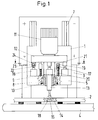
- den Gesamtaufbau der Vorrichtung in einer Frontansicht und
- Figur 2
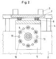
- eine Draufsicht auf die Halterung mit den auf ihr angeordneten Zylindern und Anschlägen.
- Die Vorrichtung 1 zur Herstellung von Bohrlöchern mit Hinterschneidung in Fassadenplatten 2 ist in einem Ständer 3 integriert, der eine Auflage 4 - gegebenenfalls mit Spanneinrichtung - für die Fassadenplatte 2 aufweist. Für die Vertikalbewegung der Vorrichtung 1 sind an der Halterung 5 zwei Führungsschienen 6 angeordnet, die in am Ständer 3 befestigte Führungsprofile 7 eingreifen.
- In der Halterung 5 befindet sich das Schwenklager, das durch eine Lagerbuchse 8 und einem auf der Führungshülse 9 angeordneten kugelförmigen Bund 10 gebildet ist. Die Führungshülse 9 ist fest mit der Bohrmaschine 11 und der kreisförmigen Taumelscheibe 12 verbunden. Im Bohrfutter der Bohrmaschine 11 ist der Adapter 13 eingespannt, in dessen die Führungshülse 9 überragenden Stirnende das mit Diamantsplitter bestückte Bohrwerkzeug 14 eingesteckt ist. Zum Bohren des Bohrloches 15 in der Fassadenplatte 2 wird die Vorrichtung 1 bei waagrecht stehender Taumelscheibe und eingeschalteter Bohrmaschine über ein Zahnstangengetriebe, Hebel oder dgl. (nicht dargestellt) nach unten bewegt und das zylindrische Bohrloch erstellt. Nach Erreichen der eingestellten Bohrlochtiefe wird bei laufender Bohrmaschine die Taumelscheibe 12 durch Ansteuern und Betätigen eines Zylinders 16 soweit in Schräglage gebracht, bis die Taumelscheibe auf den diesem Zylinder gegenüberliegenden Anschlägen 17 aufsitzt. Dabei wird die Achse der Bohrmaschine und des Bohrwerkzeuges entgegengesetzt um den Mittelpunkt des Schwenklagers ausgelenkt. Durch die nacheinander gesteuerte Betätigung der Zylinder 16 im oder gegen den Uhrzeigersinn entsteht eine Taumelbewegung, die zur Ausreibung der Hinterschneidung 18 des Bohrloches 15 führt. Nach ein oder zwei Umläufen wird die Taumelscheibe wieder in die waagrechte Lage gebracht und das Bohrwerkzeug aus dem Bohrloch ausgefahren.
- Der Grad der Hinterschneidung ist durch die Anschläge 17 einstellbar. Durch mehr oder weniger starkes Aufdrehen der Gewindehülse 19 auf den Gewindebolzen 20 kann der Abstand der gerundeten Stirnseite 21 der Gewindehülse 19 gegenüber der Taumelscheibe 12 verstelltwerden. Um beim Taumeln der Vorrichtung ein Verkanten der Zylinder mit der Taumelscheibe zu vermeiden, weist die Kolbenstange 22 des Zylinders 16 zur Bildung eines Pendellagers einen Kugelkopf 23 auf, der in einer zylindrischen Bohrung des Kupplungsstückes 24 eingreift.
- Um eine gleichförmige Taumelbewegung zu erreichen, sind - wie aus Figur 2 ersichtlich - auf der Halterung 5 konzentrisch um die Führungshülse 9 sechs Zylinder 16 angeordnet, die nacheinander im oder gegen den Uhrzeigersinn angesteuert werden. Auf dem gleichen Kreisdurchmesser, jeweils zwischen zwei Zylindern, sind ebenfalls sechs die Schräglage der Taumelscheibe 12 begrenzende Anschläge 17 aufgesetzt.
- Zur Erzeugung der Taumelbewegung können Pneumatik- oder Hydraulikzylinder verwendet werden. Denkbar sind jedoch auch andere linear wirkenden Antriebseinheiten, beispielsweise Hubmagnete oder Zahnstangengetriebe.
Claims (5)
- Vorrichtung zur Herstellung von Bohrlöchern mit Hinterschneidung, insbesondere in Fassadenplatten, bestehend aus einem das Bohrwerkzeug aufnehmenden und mit einer Bohrmaschine drehmomentübertragend verbundenen Adapter, und einer in einer Halterung eines Ständers befestigten Lagerbuchse, in der eine mit der Bohrmaschine fest verbundene Führungshülse über ein Schwenklager dreh- und verschwenkbar aufgenommen und gelagert ist, dadurch gekennzeichnet, daß an der Bohrmaschine (11) und Führungshülse (9) eine Taumelscheibe (12) befestigt ist, an der mehrere auf der Halterung (5) und konzentrisch um die Mittelachse der Führunghülse (9) angeordnete Zylinder (16) angreifen, die zur Erzeugung der Taumelbewegung für das Ausreiben der Hinterschneidung (18) nacheinander angesteuert und betätigt werden.
- Vorrichtung nach Anspruch 1, dadurch gekennzeichnet, daß die Kolbenstange (22) des Zylinders (16) über ein Pendelgelenk (23, 24) mit der Taumelscheibe verbunden ist.
- Vorrichtung nach Anspruch 1, dadurch gekennzeichnet, daß wenigstens sechs Zylinder (16) konzentrisch und gleichmäßig verteilt um die Mittelachse der Führungshülse (9) angeordnet sind.
- Vorrichtung nach Anspruch 1, dadurch gekennzeichnet, daß auf der Halterung (5) und konzentrisch um die Mittelachse der Führungshülse (9) mehrere vorzugsweise der Anzahl der Zylinder (16) entsprechende Anschläge (17) für die Taumelscheibe (12) angeordnet sind.
- Vorrichtung nach Anspruch 4, dadurch gekennzeichnet, daß die Anschläge (17) durch einen Gewindebolzen (20) gebildet sind, auf den eine mit einer gerundeten Stirnseite (21) versehene Gewindehülse (19) aufgeschraubt ist.
Applications Claiming Priority (2)
| Application Number | Priority Date | Filing Date | Title |
|---|---|---|---|
| DE4127745 | 1991-08-22 | ||
| DE4127745A DE4127745A1 (de) | 1991-08-22 | 1991-08-22 | Vorrichtung zur herstellung von bohrloechern mit hinterschneidung |
Publications (2)
| Publication Number | Publication Date |
|---|---|
| EP0529238A1 true EP0529238A1 (de) | 1993-03-03 |
| EP0529238B1 EP0529238B1 (de) | 1995-04-26 |
Family
ID=6438813
Family Applications (1)
| Application Number | Title | Priority Date | Filing Date |
|---|---|---|---|
| EP92111112A Expired - Lifetime EP0529238B1 (de) | 1991-08-22 | 1992-07-01 | Vorrichtung zur Herstellung von Bohrlöchern mit Hinterschneidung |
Country Status (12)
| Country | Link |
|---|---|
| US (1) | US5226763A (de) |
| EP (1) | EP0529238B1 (de) |
| JP (1) | JPH0688248B2 (de) |
| CN (1) | CN1071876A (de) |
| AT (1) | ATE121653T1 (de) |
| BR (1) | BR9203291A (de) |
| DE (2) | DE4127745A1 (de) |
| DK (1) | DK0529238T3 (de) |
| ES (1) | ES2073213T3 (de) |
| GR (1) | GR3015936T3 (de) |
| HU (1) | HU210276B (de) |
| RU (1) | RU2028943C1 (de) |
Cited By (5)
| Publication number | Priority date | Publication date | Assignee | Title |
|---|---|---|---|---|
| EP0568786A1 (de) * | 1992-05-05 | 1993-11-10 | fischerwerke Artur Fischer GmbH & Co. KG | Vorrichtung zur Herstellung von Bohrlöchern mit Hinterschneidung |
| DE4306218A1 (de) * | 1993-02-27 | 1994-09-01 | Fischer Artur Werke Gmbh | Vorrichtung zur Herstellung von Bohrlöchern mit Hinterschneidung |
| EP0633084A1 (de) * | 1993-07-10 | 1995-01-11 | Fischerwerke Arthur Fischer GmbH & Co. KG | Vorrichtung zur Herstellung von Bohrlöchern mit Hinterschneidung |
| EP0698436A1 (de) * | 1994-08-22 | 1996-02-28 | Fischerwerke Arthur Fischer GmbH & Co. KG | Bohrvorrichtung zur Herstellung von Bohrlöchern mit Hinterschneidung |
| EP0738555A1 (de) * | 1995-04-19 | 1996-10-23 | Fischerwerke Arthur Fischer GmbH & Co. KG | Bohrvorrichtung zur Herstellung von Bohrlöchern mit Hinterschneidung |
Families Citing this family (15)
| Publication number | Priority date | Publication date | Assignee | Title |
|---|---|---|---|---|
| US5452976A (en) * | 1993-04-26 | 1995-09-26 | Stone Anchors, Inc. | Anchor and method and system for securing same |
| US5378003A (en) * | 1993-05-20 | 1995-01-03 | Koller Enterprises, Inc. | Mechanic's creeper |
| DE4330058A1 (de) * | 1993-09-06 | 1995-03-09 | Fischer Artur Werke Gmbh | Bohrvorrichtung zur Herstellung von Bohrlöchern mit Hinterschneidung |
| DE4341378A1 (de) * | 1993-12-04 | 1995-06-08 | Fischer Artur Werke Gmbh | Bohrvorrichtung mit radial auslenkbarer Bohrspindel |
| US6007281A (en) * | 1998-04-09 | 1999-12-28 | Novator Ab | Method of producing holes in fiber reinforced composites using a tool with a cutting head having an enlarged diameter and reduced height |
| US5971678A (en) * | 1998-06-05 | 1999-10-26 | Novator Ab | Spindle unit |
| DE10311079A1 (de) * | 2003-03-13 | 2004-09-30 | Powers Fasteners Europe Bv | Bohrvorrichtung |
| US7755761B2 (en) * | 2004-11-12 | 2010-07-13 | The Boeing Company | Self-normalizing contour drilling machine |
| DE102010013480A1 (de) * | 2009-10-02 | 2011-04-07 | Ferroll Gmbh | Spanwerkzeug, insbesondere Schälwerkzeug, Aufbohrkopf, Vollbohrkopf oder Bohrkopf, sowie Zerspanungsmaschine und Verfahren |
| US9108250B1 (en) * | 2012-10-31 | 2015-08-18 | The Boeing Company | Adjustable bushing assemblies |
| CN104985231B (zh) * | 2015-05-14 | 2017-05-24 | 广西梧州运龙港船机械制造有限公司 | 舵机基座的钻孔方法 |
| CN108818957B (zh) * | 2018-06-11 | 2020-09-25 | 江苏上玻玻璃有限公司 | 一种钢化玻璃生产用定点防偏差的冲孔设备 |
| CN109482929B (zh) * | 2019-01-24 | 2020-07-07 | 南京华东钢管制造有限公司 | 一种钢管打孔机 |
| CN110405281B (zh) * | 2019-08-09 | 2020-06-02 | 合肥市远大轴承锻造有限公司 | 一种用于深孔内的扩孔加工装置 |
| CN110682135B (zh) * | 2019-11-06 | 2020-07-28 | 杭州联周科技有限公司 | 一种灯罩打孔装置 |
Citations (5)
| Publication number | Priority date | Publication date | Assignee | Title |
|---|---|---|---|---|
| US2823591A (en) * | 1953-11-13 | 1958-02-18 | Kaiser Metal Products Inc | Tool adjustment |
| DE1448549B1 (de) * | 1962-05-17 | 1970-03-12 | Thomson Houston Comp Francaise | Dreibeingestell zum lagegenauen Abstuetzen schwerer Geraete |
| DE3222159A1 (de) * | 1981-02-23 | 1983-12-15 | Manfred Hinn | Geraet zum herstellen von hinterschneidungen in bohrungen an treppenstufen oder anderen flaechen aus natur- und/oder werkstein |
| DE3239192A1 (de) * | 1982-10-22 | 1984-05-17 | Peter 6550 Bad Kreuznach Bussmer | Vorrichtung zum einfraesen einer schraubenfoermigen nut in die seitenwand eines vorgebohrten loches |
| EP0484647A1 (de) * | 1990-11-08 | 1992-05-13 | fischerwerke Artur Fischer GmbH & Co. KG | Vorrichtung zur Herstellung von Bohrlöchern mit Hinterschneidung |
Family Cites Families (12)
| Publication number | Priority date | Publication date | Assignee | Title |
|---|---|---|---|---|
| US2969000A (en) * | 1957-09-24 | 1961-01-24 | Cleaver Brooks Co | Chamfering tool |
| FR2445755A1 (fr) * | 1979-01-08 | 1980-08-01 | Harmand Pierre | Broche porte-outils pour usinage de precision |
| DE3106612A1 (de) * | 1981-02-23 | 1982-09-02 | Manfred Hinn | "geraet zum zurichten von treppenstufen aus natur- und/oder werkstein" |
| DE3206387A1 (de) * | 1982-02-22 | 1983-09-01 | Hilti AG, 9494 Schaan | Bohrwerkzeug fuer hinterschnittene bohrungen |
| DE3704491A1 (de) * | 1987-02-13 | 1988-08-25 | Upat Max Langensiepen Kg | Hinterschnittfbohrer |
| DE3809761A1 (de) * | 1988-03-23 | 1989-10-05 | Hilti Ag | Hinterschnitt-bohrvorrichtung |
| DE3924044A1 (de) * | 1989-07-21 | 1991-01-24 | Fischer Artur Werke Gmbh | Vorrichtung zur herstellung einer hinterschneidung in einem bohrloch |
| DE4004485A1 (de) * | 1990-02-14 | 1991-08-22 | Fischer Artur Werke Gmbh | Vorrichtung zur herstellung von bohrloechern mit hinterschneidung |
| US5018912A (en) * | 1990-05-18 | 1991-05-28 | By George Enterprises, Inc. | Drilling jig for stair rails |
| DE9104316U1 (de) * | 1991-04-10 | 1991-06-13 | Zumtobel Ag, Dornbirn | Leuchtenabdeckung, insbesondere für Leuchtstofflampen |
| JP3126510U (ja) | 2006-04-21 | 2006-11-02 | 株式会社測研 | 角柱型鉄塔若しくは、四角錐型送電線鉄塔番号 |
| JP5422632B2 (ja) | 2011-11-02 | 2014-02-19 | 京セラドキュメントソリューションズ株式会社 | 現像装置及びそれを備えた画像形成装置 |
-
1991
- 1991-08-22 DE DE4127745A patent/DE4127745A1/de not_active Withdrawn
-
1992
- 1992-07-01 ES ES92111112T patent/ES2073213T3/es not_active Expired - Lifetime
- 1992-07-01 AT AT92111112T patent/ATE121653T1/de not_active IP Right Cessation
- 1992-07-01 DK DK92111112.6T patent/DK0529238T3/da active
- 1992-07-01 DE DE59202018T patent/DE59202018D1/de not_active Expired - Fee Related
- 1992-07-01 EP EP92111112A patent/EP0529238B1/de not_active Expired - Lifetime
- 1992-08-11 HU HU9202612A patent/HU210276B/hu not_active IP Right Cessation
- 1992-08-18 JP JP4219180A patent/JPH0688248B2/ja not_active Expired - Lifetime
- 1992-08-21 RU SU925052590A patent/RU2028943C1/ru active
- 1992-08-21 BR BR929203291A patent/BR9203291A/pt active Search and Examination
- 1992-08-22 CN CN92109739.5A patent/CN1071876A/zh active Pending
- 1992-08-24 US US07/935,051 patent/US5226763A/en not_active Expired - Fee Related
-
1995
- 1995-04-27 GR GR940404100T patent/GR3015936T3/el unknown
Patent Citations (5)
| Publication number | Priority date | Publication date | Assignee | Title |
|---|---|---|---|---|
| US2823591A (en) * | 1953-11-13 | 1958-02-18 | Kaiser Metal Products Inc | Tool adjustment |
| DE1448549B1 (de) * | 1962-05-17 | 1970-03-12 | Thomson Houston Comp Francaise | Dreibeingestell zum lagegenauen Abstuetzen schwerer Geraete |
| DE3222159A1 (de) * | 1981-02-23 | 1983-12-15 | Manfred Hinn | Geraet zum herstellen von hinterschneidungen in bohrungen an treppenstufen oder anderen flaechen aus natur- und/oder werkstein |
| DE3239192A1 (de) * | 1982-10-22 | 1984-05-17 | Peter 6550 Bad Kreuznach Bussmer | Vorrichtung zum einfraesen einer schraubenfoermigen nut in die seitenwand eines vorgebohrten loches |
| EP0484647A1 (de) * | 1990-11-08 | 1992-05-13 | fischerwerke Artur Fischer GmbH & Co. KG | Vorrichtung zur Herstellung von Bohrlöchern mit Hinterschneidung |
Cited By (5)
| Publication number | Priority date | Publication date | Assignee | Title |
|---|---|---|---|---|
| EP0568786A1 (de) * | 1992-05-05 | 1993-11-10 | fischerwerke Artur Fischer GmbH & Co. KG | Vorrichtung zur Herstellung von Bohrlöchern mit Hinterschneidung |
| DE4306218A1 (de) * | 1993-02-27 | 1994-09-01 | Fischer Artur Werke Gmbh | Vorrichtung zur Herstellung von Bohrlöchern mit Hinterschneidung |
| EP0633084A1 (de) * | 1993-07-10 | 1995-01-11 | Fischerwerke Arthur Fischer GmbH & Co. KG | Vorrichtung zur Herstellung von Bohrlöchern mit Hinterschneidung |
| EP0698436A1 (de) * | 1994-08-22 | 1996-02-28 | Fischerwerke Arthur Fischer GmbH & Co. KG | Bohrvorrichtung zur Herstellung von Bohrlöchern mit Hinterschneidung |
| EP0738555A1 (de) * | 1995-04-19 | 1996-10-23 | Fischerwerke Arthur Fischer GmbH & Co. KG | Bohrvorrichtung zur Herstellung von Bohrlöchern mit Hinterschneidung |
Also Published As
| Publication number | Publication date |
|---|---|
| ATE121653T1 (de) | 1995-05-15 |
| ES2073213T3 (es) | 1995-08-01 |
| DK0529238T3 (da) | 1995-08-28 |
| DE59202018D1 (de) | 1995-06-01 |
| RU2028943C1 (ru) | 1995-02-20 |
| CN1071876A (zh) | 1993-05-12 |
| EP0529238B1 (de) | 1995-04-26 |
| HU210276B (en) | 1995-03-28 |
| DE4127745A1 (de) | 1993-02-25 |
| JPH05192921A (ja) | 1993-08-03 |
| US5226763A (en) | 1993-07-13 |
| JPH0688248B2 (ja) | 1994-11-09 |
| GR3015936T3 (en) | 1995-07-31 |
| BR9203291A (pt) | 1993-04-06 |
| HUT62511A (en) | 1993-05-28 |
Similar Documents
| Publication | Publication Date | Title |
|---|---|---|
| EP0529238B1 (de) | Vorrichtung zur Herstellung von Bohrlöchern mit Hinterschneidung | |
| DE102014009478A1 (de) | Manipulator mit einem Manipulatorarm | |
| EP0475891B1 (de) | Verfahren und Mittel zur Herstellung von Bohrungen | |
| EP0484647B1 (de) | Vorrichtung zur Herstellung von Bohrlöchern mit Hinterschneidung | |
| EP0568786B1 (de) | Vorrichtung zur Herstellung von Bohrlöchern mit Hinterschneidung | |
| DE4004485A1 (de) | Vorrichtung zur herstellung von bohrloechern mit hinterschneidung | |
| DE4431286C2 (de) | Linearführung | |
| DE3344064A1 (de) | Haltevorrichtung fuer bohrgeraete | |
| DE19501663A1 (de) | Höhenverstellbarer Werkzeughalter | |
| DE3725014A1 (de) | Werkzeug fuer tiefliegende innenbearbeitung hohler werkstuecke | |
| EP0994759B1 (de) | Lochsägeneinrichtung mit auswerfereinrichtung | |
| EP0344117B1 (de) | Verfahren und Vorrichtung zum Walzen von Nuten in Einsteckenden von Werkzeugen | |
| DE3239192C2 (de) | Vorrichtung zum Einfräsen einer schraubenlinienförmig verlaufenden Nut in die Seitenwand von Bohrungen in Werkstücken aus Natur- oder Kunststein | |
| EP1428972A2 (de) | Vorrichtung mit wenigstens einer Bohrmaschine | |
| EP0770442B1 (de) | Tieflochsäge | |
| AT1538U1 (de) | Bohrhaltevorrichtung mit bohrer | |
| DE3528278A1 (de) | Bohrvorrichtung fuer schaechte | |
| EP1366843A2 (de) | Vorrichtung zur Herstellung von Schräglochbohrungen in Rohren | |
| DE3506343A1 (de) | Laengenverstellbare abspannsaeule zur aufnahme einer lafettenbohrmaschine | |
| DE19544265C1 (de) | Rundtakt-Werkzeugmaschine | |
| DE10111834A1 (de) | Halterungsvorrichtung | |
| AT315009B (de) | Vorrichtung zum Hohen von konischen Bohrungen | |
| DE2814197A1 (de) | Bohrstaender | |
| DE3528277A1 (de) | Ankerbohrgeraet fuer schaechte | |
| DE20109786U1 (de) | Bohrvorrichtung zur Fußbodenleistenbefestigung |
Legal Events
| Date | Code | Title | Description |
|---|---|---|---|
| PUAI | Public reference made under article 153(3) epc to a published international application that has entered the european phase |
Free format text: ORIGINAL CODE: 0009012 |
|
| AK | Designated contracting states |
Kind code of ref document: A1 Designated state(s): AT BE CH DE DK ES FR GB GR IT LI LU NL PT SE |
|
| 17P | Request for examination filed |
Effective date: 19930712 |
|
| 17Q | First examination report despatched |
Effective date: 19931227 |
|
| GRAA | (expected) grant |
Free format text: ORIGINAL CODE: 0009210 |
|
| AK | Designated contracting states |
Kind code of ref document: B1 Designated state(s): AT BE CH DE DK ES FR GB GR IT LI LU NL PT SE |
|
| PG25 | Lapsed in a contracting state [announced via postgrant information from national office to epo] |
Ref country code: GR Free format text: LAPSE BECAUSE OF FAILURE TO SUBMIT A TRANSLATION OF THE DESCRIPTION OR TO PAY THE FEE WITHIN THE PRESCRIBED TIME-LIMIT Effective date: 19950426 |
|
| REF | Corresponds to: |
Ref document number: 121653 Country of ref document: AT Date of ref document: 19950515 Kind code of ref document: T |
|
| ET | Fr: translation filed | ||
| REF | Corresponds to: |
Ref document number: 59202018 Country of ref document: DE Date of ref document: 19950601 |
|
| ITF | It: translation for a ep patent filed | ||
| REG | Reference to a national code |
Ref country code: GR Ref legal event code: FG4A Free format text: 3015936 |
|
| PG25 | Lapsed in a contracting state [announced via postgrant information from national office to epo] |
Ref country code: LU Free format text: LAPSE BECAUSE OF NON-PAYMENT OF DUE FEES Effective date: 19950731 |
|
| REG | Reference to a national code |
Ref country code: ES Ref legal event code: FG2A Ref document number: 2073213 Country of ref document: ES Kind code of ref document: T3 |
|
| REG | Reference to a national code |
Ref country code: DK Ref legal event code: T3 |
|
| GBT | Gb: translation of ep patent filed (gb section 77(6)(a)/1977) |
Effective date: 19950807 |
|
| PLBE | No opposition filed within time limit |
Free format text: ORIGINAL CODE: 0009261 |
|
| STAA | Information on the status of an ep patent application or granted ep patent |
Free format text: STATUS: NO OPPOSITION FILED WITHIN TIME LIMIT |
|
| REG | Reference to a national code |
Ref country code: GR Ref legal event code: MM2A Free format text: 3015936 |
|
| 26N | No opposition filed | ||
| PGFP | Annual fee paid to national office [announced via postgrant information from national office to epo] |
Ref country code: PT Payment date: 19970611 Year of fee payment: 6 |
|
| PGFP | Annual fee paid to national office [announced via postgrant information from national office to epo] |
Ref country code: GB Payment date: 19970623 Year of fee payment: 6 |
|
| PGFP | Annual fee paid to national office [announced via postgrant information from national office to epo] |
Ref country code: SE Payment date: 19970702 Year of fee payment: 6 |
|
| PGFP | Annual fee paid to national office [announced via postgrant information from national office to epo] |
Ref country code: BE Payment date: 19970716 Year of fee payment: 6 |
|
| PGFP | Annual fee paid to national office [announced via postgrant information from national office to epo] |
Ref country code: AT Payment date: 19970717 Year of fee payment: 6 |
|
| PGFP | Annual fee paid to national office [announced via postgrant information from national office to epo] |
Ref country code: ES Payment date: 19970723 Year of fee payment: 6 |
|
| PGFP | Annual fee paid to national office [announced via postgrant information from national office to epo] |
Ref country code: CH Payment date: 19970724 Year of fee payment: 6 |
|
| PGFP | Annual fee paid to national office [announced via postgrant information from national office to epo] |
Ref country code: DK Payment date: 19970730 Year of fee payment: 6 |
|
| PGFP | Annual fee paid to national office [announced via postgrant information from national office to epo] |
Ref country code: NL Payment date: 19970731 Year of fee payment: 6 |
|
| PGFP | Annual fee paid to national office [announced via postgrant information from national office to epo] |
Ref country code: FR Payment date: 19980528 Year of fee payment: 7 |
|
| PG25 | Lapsed in a contracting state [announced via postgrant information from national office to epo] |
Ref country code: AT Free format text: LAPSE BECAUSE OF NON-PAYMENT OF DUE FEES Effective date: 19980701 Ref country code: GB Free format text: LAPSE BECAUSE OF NON-PAYMENT OF DUE FEES Effective date: 19980701 |
|
| PG25 | Lapsed in a contracting state [announced via postgrant information from national office to epo] |
Ref country code: SE Free format text: LAPSE BECAUSE OF NON-PAYMENT OF DUE FEES Effective date: 19980702 Ref country code: ES Free format text: LAPSE BECAUSE OF THE APPLICANT RENOUNCES Effective date: 19980702 |
|
| PG25 | Lapsed in a contracting state [announced via postgrant information from national office to epo] |
Ref country code: LI Free format text: LAPSE BECAUSE OF NON-PAYMENT OF DUE FEES Effective date: 19980731 Ref country code: BE Free format text: LAPSE BECAUSE OF NON-PAYMENT OF DUE FEES Effective date: 19980731 Ref country code: DK Free format text: LAPSE BECAUSE OF NON-PAYMENT OF DUE FEES Effective date: 19980731 Ref country code: CH Free format text: LAPSE BECAUSE OF NON-PAYMENT OF DUE FEES Effective date: 19980731 |
|
| BERE | Be: lapsed |
Owner name: FISCHERWERKE ARTUR FISCHER G.M.B.H. & CO. K.G. Effective date: 19980731 |
|
| PG25 | Lapsed in a contracting state [announced via postgrant information from national office to epo] |
Ref country code: PT Free format text: LAPSE BECAUSE OF NON-PAYMENT OF DUE FEES Effective date: 19990131 |
|
| PG25 | Lapsed in a contracting state [announced via postgrant information from national office to epo] |
Ref country code: NL Free format text: LAPSE BECAUSE OF NON-PAYMENT OF DUE FEES Effective date: 19990201 |
|
| GBPC | Gb: european patent ceased through non-payment of renewal fee |
Effective date: 19980701 |
|
| REG | Reference to a national code |
Ref country code: CH Ref legal event code: PL |
|
| EUG | Se: european patent has lapsed |
Ref document number: 92111112.6 |
|
| NLV4 | Nl: lapsed or anulled due to non-payment of the annual fee |
Effective date: 19990201 |
|
| REG | Reference to a national code |
Ref country code: PT Ref legal event code: MM4A Free format text: LAPSE DUE TO NON-PAYMENT OF FEES Effective date: 19990131 |
|
| PG25 | Lapsed in a contracting state [announced via postgrant information from national office to epo] |
Ref country code: FR Free format text: THE PATENT HAS BEEN ANNULLED BY A DECISION OF A NATIONAL AUTHORITY Effective date: 19990731 |
|
| REG | Reference to a national code |
Ref country code: DK Ref legal event code: EBP |
|
| REG | Reference to a national code |
Ref country code: FR Ref legal event code: ST |
|
| REG | Reference to a national code |
Ref country code: ES Ref legal event code: FD2A Effective date: 20001009 |
|
| PGFP | Annual fee paid to national office [announced via postgrant information from national office to epo] |
Ref country code: DE Payment date: 20030521 Year of fee payment: 12 |
|
| PG25 | Lapsed in a contracting state [announced via postgrant information from national office to epo] |
Ref country code: DE Free format text: LAPSE BECAUSE OF NON-PAYMENT OF DUE FEES Effective date: 20050201 |
|
| PG25 | Lapsed in a contracting state [announced via postgrant information from national office to epo] |
Ref country code: IT Free format text: LAPSE BECAUSE OF NON-PAYMENT OF DUE FEES;WARNING: LAPSES OF ITALIAN PATENTS WITH EFFECTIVE DATE BEFORE 2007 MAY HAVE OCCURRED AT ANY TIME BEFORE 2007. THE CORRECT EFFECTIVE DATE MAY BE DIFFERENT FROM THE ONE RECORDED. Effective date: 20050701 |