EP0529333A1 - Kontinuierlicher Knetapparat - Google Patents
Kontinuierlicher Knetapparat Download PDFInfo
- Publication number
- EP0529333A1 EP0529333A1 EP92112928A EP92112928A EP0529333A1 EP 0529333 A1 EP0529333 A1 EP 0529333A1 EP 92112928 A EP92112928 A EP 92112928A EP 92112928 A EP92112928 A EP 92112928A EP 0529333 A1 EP0529333 A1 EP 0529333A1
- Authority
- EP
- European Patent Office
- Prior art keywords
- rotatable
- members
- discs
- fixed
- side faces
- Prior art date
- Legal status (The legal status is an assumption and is not a legal conclusion. Google has not performed a legal analysis and makes no representation as to the accuracy of the status listed.)
- Granted
Links
Images



Classifications
-
- B—PERFORMING OPERATIONS; TRANSPORTING
- B29—WORKING OF PLASTICS; WORKING OF SUBSTANCES IN A PLASTIC STATE IN GENERAL
- B29B—PREPARATION OR PRETREATMENT OF THE MATERIAL TO BE SHAPED; MAKING GRANULES OR PREFORMS; RECOVERY OF PLASTICS OR OTHER CONSTITUENTS OF WASTE MATERIAL CONTAINING PLASTICS
- B29B7/00—Mixing; Kneading
- B29B7/30—Mixing; Kneading continuous, with mechanical mixing or kneading devices
- B29B7/34—Mixing; Kneading continuous, with mechanical mixing or kneading devices with movable mixing or kneading devices
- B29B7/38—Mixing; Kneading continuous, with mechanical mixing or kneading devices with movable mixing or kneading devices rotary
- B29B7/40—Mixing; Kneading continuous, with mechanical mixing or kneading devices with movable mixing or kneading devices rotary with single shaft
- B29B7/42—Mixing; Kneading continuous, with mechanical mixing or kneading devices with movable mixing or kneading devices rotary with single shaft with screw or helix
- B29B7/421—Mixing; Kneading continuous, with mechanical mixing or kneading devices with movable mixing or kneading devices rotary with single shaft with screw or helix with screw and additionally other mixing elements on the same shaft, e.g. paddles, discs, bearings, rotor blades of the Banbury type
-
- B—PERFORMING OPERATIONS; TRANSPORTING
- B29—WORKING OF PLASTICS; WORKING OF SUBSTANCES IN A PLASTIC STATE IN GENERAL
- B29B—PREPARATION OR PRETREATMENT OF THE MATERIAL TO BE SHAPED; MAKING GRANULES OR PREFORMS; RECOVERY OF PLASTICS OR OTHER CONSTITUENTS OF WASTE MATERIAL CONTAINING PLASTICS
- B29B7/00—Mixing; Kneading
- B29B7/30—Mixing; Kneading continuous, with mechanical mixing or kneading devices
- B29B7/34—Mixing; Kneading continuous, with mechanical mixing or kneading devices with movable mixing or kneading devices
- B29B7/38—Mixing; Kneading continuous, with mechanical mixing or kneading devices with movable mixing or kneading devices rotary
- B29B7/40—Mixing; Kneading continuous, with mechanical mixing or kneading devices with movable mixing or kneading devices rotary with single shaft
- B29B7/402—Mixing; Kneading continuous, with mechanical mixing or kneading devices with movable mixing or kneading devices rotary with single shaft using a rotor-stator system with intermeshing elements, e.g. teeth
-
- B—PERFORMING OPERATIONS; TRANSPORTING
- B29—WORKING OF PLASTICS; WORKING OF SUBSTANCES IN A PLASTIC STATE IN GENERAL
- B29B—PREPARATION OR PRETREATMENT OF THE MATERIAL TO BE SHAPED; MAKING GRANULES OR PREFORMS; RECOVERY OF PLASTICS OR OTHER CONSTITUENTS OF WASTE MATERIAL CONTAINING PLASTICS
- B29B7/00—Mixing; Kneading
- B29B7/30—Mixing; Kneading continuous, with mechanical mixing or kneading devices
- B29B7/34—Mixing; Kneading continuous, with mechanical mixing or kneading devices with movable mixing or kneading devices
- B29B7/38—Mixing; Kneading continuous, with mechanical mixing or kneading devices with movable mixing or kneading devices rotary
- B29B7/40—Mixing; Kneading continuous, with mechanical mixing or kneading devices with movable mixing or kneading devices rotary with single shaft
- B29B7/42—Mixing; Kneading continuous, with mechanical mixing or kneading devices with movable mixing or kneading devices rotary with single shaft with screw or helix
- B29B7/422—Mixing; Kneading continuous, with mechanical mixing or kneading devices with movable mixing or kneading devices rotary with single shaft with screw or helix with screw sections co-operating, e.g. intermeshing, with elements on the wall of the surrounding casing
-
- B—PERFORMING OPERATIONS; TRANSPORTING
- B29—WORKING OF PLASTICS; WORKING OF SUBSTANCES IN A PLASTIC STATE IN GENERAL
- B29B—PREPARATION OR PRETREATMENT OF THE MATERIAL TO BE SHAPED; MAKING GRANULES OR PREFORMS; RECOVERY OF PLASTICS OR OTHER CONSTITUENTS OF WASTE MATERIAL CONTAINING PLASTICS
- B29B7/00—Mixing; Kneading
- B29B7/30—Mixing; Kneading continuous, with mechanical mixing or kneading devices
- B29B7/34—Mixing; Kneading continuous, with mechanical mixing or kneading devices with movable mixing or kneading devices
- B29B7/38—Mixing; Kneading continuous, with mechanical mixing or kneading devices with movable mixing or kneading devices rotary
- B29B7/40—Mixing; Kneading continuous, with mechanical mixing or kneading devices with movable mixing or kneading devices rotary with single shaft
- B29B7/42—Mixing; Kneading continuous, with mechanical mixing or kneading devices with movable mixing or kneading devices rotary with single shaft with screw or helix
- B29B7/428—Parts or accessories, e.g. casings, feeding or discharging means
-
- B—PERFORMING OPERATIONS; TRANSPORTING
- B29—WORKING OF PLASTICS; WORKING OF SUBSTANCES IN A PLASTIC STATE IN GENERAL
- B29C—SHAPING OR JOINING OF PLASTICS; SHAPING OF MATERIAL IN A PLASTIC STATE, NOT OTHERWISE PROVIDED FOR; AFTER-TREATMENT OF THE SHAPED PRODUCTS, e.g. REPAIRING
- B29C48/00—Extrusion moulding, i.e. expressing the moulding material through a die or nozzle which imparts the desired form; Apparatus therefor
- B29C48/25—Component parts, details or accessories; Auxiliary operations
- B29C48/36—Means for plasticising or homogenising the moulding material or forcing it through the nozzle or die
- B29C48/375—Plasticisers, homogenisers or feeders comprising two or more stages
- B29C48/39—Plasticisers, homogenisers or feeders comprising two or more stages a first extruder feeding the melt into an intermediate location of a second extruder
-
- B—PERFORMING OPERATIONS; TRANSPORTING
- B29—WORKING OF PLASTICS; WORKING OF SUBSTANCES IN A PLASTIC STATE IN GENERAL
- B29C—SHAPING OR JOINING OF PLASTICS; SHAPING OF MATERIAL IN A PLASTIC STATE, NOT OTHERWISE PROVIDED FOR; AFTER-TREATMENT OF THE SHAPED PRODUCTS, e.g. REPAIRING
- B29C48/00—Extrusion moulding, i.e. expressing the moulding material through a die or nozzle which imparts the desired form; Apparatus therefor
- B29C48/25—Component parts, details or accessories; Auxiliary operations
- B29C48/36—Means for plasticising or homogenising the moulding material or forcing it through the nozzle or die
- B29C48/395—Means for plasticising or homogenising the moulding material or forcing it through the nozzle or die using screws surrounded by a cooperating barrel, e.g. single screw extruders
- B29C48/397—Means for plasticising or homogenising the moulding material or forcing it through the nozzle or die using screws surrounded by a cooperating barrel, e.g. single screw extruders using a single screw
-
- B—PERFORMING OPERATIONS; TRANSPORTING
- B29—WORKING OF PLASTICS; WORKING OF SUBSTANCES IN A PLASTIC STATE IN GENERAL
- B29C—SHAPING OR JOINING OF PLASTICS; SHAPING OF MATERIAL IN A PLASTIC STATE, NOT OTHERWISE PROVIDED FOR; AFTER-TREATMENT OF THE SHAPED PRODUCTS, e.g. REPAIRING
- B29C48/00—Extrusion moulding, i.e. expressing the moulding material through a die or nozzle which imparts the desired form; Apparatus therefor
- B29C48/25—Component parts, details or accessories; Auxiliary operations
- B29C48/36—Means for plasticising or homogenising the moulding material or forcing it through the nozzle or die
- B29C48/47—Means for plasticising or homogenising the moulding material or forcing it through the nozzle or die using discs, e.g. plasticising the moulding material by passing it between a fixed and a rotating disc that are coaxially arranged
-
- B—PERFORMING OPERATIONS; TRANSPORTING
- B29—WORKING OF PLASTICS; WORKING OF SUBSTANCES IN A PLASTIC STATE IN GENERAL
- B29C—SHAPING OR JOINING OF PLASTICS; SHAPING OF MATERIAL IN A PLASTIC STATE, NOT OTHERWISE PROVIDED FOR; AFTER-TREATMENT OF THE SHAPED PRODUCTS, e.g. REPAIRING
- B29C48/00—Extrusion moulding, i.e. expressing the moulding material through a die or nozzle which imparts the desired form; Apparatus therefor
- B29C48/25—Component parts, details or accessories; Auxiliary operations
- B29C48/36—Means for plasticising or homogenising the moulding material or forcing it through the nozzle or die
- B29C48/50—Details of extruders
- B29C48/505—Screws
- B29C48/52—Screws with an outer diameter varying along the longitudinal axis, e.g. for obtaining different thread clearance
-
- B—PERFORMING OPERATIONS; TRANSPORTING
- B29—WORKING OF PLASTICS; WORKING OF SUBSTANCES IN A PLASTIC STATE IN GENERAL
- B29C—SHAPING OR JOINING OF PLASTICS; SHAPING OF MATERIAL IN A PLASTIC STATE, NOT OTHERWISE PROVIDED FOR; AFTER-TREATMENT OF THE SHAPED PRODUCTS, e.g. REPAIRING
- B29C48/00—Extrusion moulding, i.e. expressing the moulding material through a die or nozzle which imparts the desired form; Apparatus therefor
- B29C48/25—Component parts, details or accessories; Auxiliary operations
- B29C48/36—Means for plasticising or homogenising the moulding material or forcing it through the nozzle or die
- B29C48/50—Details of extruders
- B29C48/68—Barrels or cylinders
- B29C48/685—Barrels or cylinders characterised by their inner surfaces, e.g. having grooves, projections or threads
- B29C48/686—Barrels or cylinders characterised by their inner surfaces, e.g. having grooves, projections or threads having grooves or cavities
-
- B—PERFORMING OPERATIONS; TRANSPORTING
- B29—WORKING OF PLASTICS; WORKING OF SUBSTANCES IN A PLASTIC STATE IN GENERAL
- B29B—PREPARATION OR PRETREATMENT OF THE MATERIAL TO BE SHAPED; MAKING GRANULES OR PREFORMS; RECOVERY OF PLASTICS OR OTHER CONSTITUENTS OF WASTE MATERIAL CONTAINING PLASTICS
- B29B7/00—Mixing; Kneading
- B29B7/30—Mixing; Kneading continuous, with mechanical mixing or kneading devices
- B29B7/58—Component parts, details or accessories; Auxiliary operations
- B29B7/60—Component parts, details or accessories; Auxiliary operations for feeding, e.g. end guides for the incoming material
-
- B—PERFORMING OPERATIONS; TRANSPORTING
- B29—WORKING OF PLASTICS; WORKING OF SUBSTANCES IN A PLASTIC STATE IN GENERAL
- B29B—PREPARATION OR PRETREATMENT OF THE MATERIAL TO BE SHAPED; MAKING GRANULES OR PREFORMS; RECOVERY OF PLASTICS OR OTHER CONSTITUENTS OF WASTE MATERIAL CONTAINING PLASTICS
- B29B7/00—Mixing; Kneading
- B29B7/80—Component parts, details or accessories; Auxiliary operations
- B29B7/82—Heating or cooling
Definitions
- This invention relates to a continuous kneading apparatus capable of kneading a variety of material and having a small construction.
- continuous kneading apparatus having the following construction.
- a feed section and a kneading section are formed such that material fed through an supply port into a cylinder provided with a rotatable screw shaft therein is continuously kneaded while being fed according to rotation of the screw shaft, and then extruded.
- a continuous kneading apparatus having a small construction, and yet capable of carrying out sufficient kneading.
- Such a continuous kneading apparatus is disclosed in, for example, Examined Japanese Patent Publication No. 2-92.
- the material is subjected to the shear force while being fed radially outwards from center portions of the rotatable disc or being fed radially inwards from the outer portions thereof. Accordingly, the magnitude of the shear force acting on the material differs in a region close to the center portion and a region away therefrom based on a difference in the relative speed of the rotatable discs and fixed doughnut members in a circumferential direction.
- the shear rate ⁇ is in proportion to the relative speed of the rotatable discs and fixed doughnut members. Since the thickness of the shear layer is normally fixed, the shearing stress ⁇ varies in proportion to the above relative speed. Accordingly, the proper shear force cannot be applied to the entire material.
- a kneading apparatus of the invention comprises a cylinder, a rotatable shaft disposed in the cylinder, the rotatable shaft having a helical thread defined on an outer circumferential surface thereof so as to feed fluid material in an extending direction thereof, a plurality of rotatable discs each mounted on the rotatable shaft, and a plurality of fixed members in the form of doughnut mounted on an inner wall of the cylinder coaxially with the rotatable discs.
- the plurality of rotatable discs and fixed members are arranged alternately in the extending direction of the rotatable shaft so that the side faces of the rotatable discs oppose to the corresponding side faces of the fixed members.
- Projected portions and recessed portions are formed on opposite side faces of the rotatable discs and fixed members, the projected portions and recessed portions extending radially and arranged alternately in a circumferential direction on each side face.
- the projected portions and recessed portions of the rotatable discs and fixed members are formed such that the distance between the opposing rotatable discs and fixed members along the extending direction of the rotatable shaft is increased in proportion to the distance from a center of a rotatable shaft.
- the recessed portions formed on either the rotatable discs or fixed doughnut members, or recessed portions formed on both the rotatable discs and fixed doughnut members may be formed such that the depth thereof is increased in proportion to the distance from a center of the rotatable shaft.
- boundary lines between two adjacent projected portions and recessed portions formed on one and the other side faces of the rotatable discs may be formed to extend in such directions that the material fed between one side faces of the rotatable discs and fixed members is fed radially outwards, and then fed radially inwards between the other side faces of the rotatable discs and next fixed members through space between outer circumferential surfaces of the rotatable discs and the inner wall of the cylinder.
- Fig. 1 is a vertical sectional view showing a center portion of a kneading apparatus embodying the invention.
- a cylinder To the cylinder 1 is connected a hopper 4 by way of a supply port 1c and a quantity measuring feeder 1a.
- a rotatable shaft 31 In the cylinder 1 is inserted a rotatable shaft 31 which is rotated by a driving device 2. Threads are formed on the rotatable shaft 31 almost entirely from a base end up to a forward end thereof.
- a thread 3 formed on the base end portion of the shaft 31 and another thread 59 formed on the forward end portion thereof constitute a feeding section F and an extruding section X respectively.
- Rotatable discs 6, 9, and 11 are disposed at specified intervals between the feeding section F and extruding section X. Further, another rotatable disc 13 having a width larger than that of the discs 6, 9, and 11 is disposed between the disc 11 and the extruding section X.
- the rotatable discs 6, 9, and 11 constitutes a kneading section K1 and the rotatable disc 13 constitutes a venting section V. Threads 10 are formed on the shaft 31 between these rotatable discs 6. 9, 11, and 13.
- annular members 14, 17, and 20 corresponding to the rotatable discs 6, 9, and 11, fixed doughnut members 16, 18, and 21 disposed between the discs 6, 9, and 11, annular member 22 having a vent hole 12, and fixed doughnut member 28 disposed downstream of the member 22 with respect to a direction of feed of material.
- These members are integrally joined between the hollow cylinders 1 and 30 in the above described order by a tie rod 24, and constitute a joined hollow cylinder.
- heaters 5 On outer circumferential surfaces of the hollow cylinders are disposed heaters 5.
- a groove 8 extending continuously in a shaft direction.
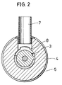
- An upstream end of groove 8 is in communication with a vent hole 7 opening outwards as shown in Fig. 2.
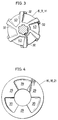
- a plurality of projected portions 32 are formed on opposite side faces of the rotatable discs 6, 9, and 11.
- the projected portions 32 are extending radially from its centers and equally and circumferentially spaced apart. Between two adjacent projected portions 32 is formed a recessed portion 43.
- the recessed portion 43 is formed such that the depth thereof become shallower at the center than at an radially outer portion of the rotatable disc.
- Outer radial ends of the projected portions 32 project radially outwardly of the outer circumferential ends of the rotatable discs 6, 9, and 11, and extend spirally in the shaft direction, thereby forming threads on the outer circumferential surfaces of the discs 6, 9, and 11.
- On inner circumferential surfaces of the annular members 14, 17, and 20 opposing the outer circumferential surfaces of the rotatable discs 6, 9, and 11 are formed grooves 23 extending in the shaft direction.
- recessed portions 39 are formed on each of side faces of the fixed doughnut members 16, 18, and 21 opposing the respective rotatable discs 6, 9, and 11 with equally and circumferentially spaced apart. Between two adjacent recessed portions 39 is formed a projected portion 29.
- the recessed portion 39 is formed such that the depth thereof become shallower at the center than at an radially outer portion of the fixed doughnut member.
- the projected portions 32 formed on the respective rotatable discs extend radially outwards with slightly tilted.
- the projected portions 32 formed on the side face of the rotatable discs facing an inlet side of the kneading apparatus extend in such a direction as to tilt relative to the radial directions thereof more in a direction of rotation at the radially outer portions.
- the projected portions 32 formed on the side face of the rotatable discs facing an outlet side of the kneading apparatus extend in such a direction as to tilt relative to the radial directions thereof more in a direction reverse of the direction of rotation at the radially outer portions.
- the rotatable discs and fixed doughnut members may be arranged in such a manner that an area defined therebetween, i.e. a flow passage area of material, becomes smaller at a downstream portion of the kneading apparatus.
- the rotatable disc and fixed doughnut members may be formed with an increased number of the projected portions or shallower recessed portions at the downstream portion of the kneading apparatus.
- a plurality of grooves 23 extending in the shaft direction are formed on inner circumferential surfaces of the annular members 14, 17, and 20.
- the annular members and rotatable discs are arranged such that the inner circumferential surfaces of the annular members oppose the outer circumferential surfaces of the rotatable discs. Accordingly, the projected portions and recessed portions formed on the circumferential surfaces of the annular members and rotatable discs are alternately opposed to each other similarly to the arrangement of the projected portions and recessed portions formed on the side faces of the rotatable discs and fixed doughnut members.
- the outer circumferential surface of the rotatable disc 13 and the inner circumferential surface of the annular member 22 are formed similarly to those of other rotatable discs and annular members.
- recessed portions 39 and 43 are variously changeable in shape although Fig. 7 illustrates those formed with a fixed radius of curvature R.
- Fig. 8 it may be appropriate to form recessed portions 391 and 431 whose cross-sections are formed with a combination of a larger radius of curvature R and a smaller radius of curvature r.
- Such recessed portions may be formed in such a manner that rear walls thereof with respect to a material feeding direction have the smaller radius of curvature r. The recessed portions thus formed will serve to strongly compress the material being fed.
- the rotatable shaft 31 is rotated by the driving device 2 and the quantity measuring feeder 1a is actuated to feed material in the hopper 4 into the hollow cylinder 1 by a specified amount. Since the inside of the hollow cylinder 1 is heated by the heater 5, the material fed thereinto are fed towards the rotatable disc 6 while being dried. Gases produced during this time is discharged through the groove 28 and vent hole 7. The material reaching the rotatable disc 6 is fed through the space between the outer circumferential surface of the disc 6 and inner circumferential surface of the annular member 14, and then fed radially inwards by relative movement of the opposing side faces of the disc 6 and fixed doughnut member 16.
- the material is then fed to a more downstream side by the thread 10 through the space between the inner circumferential surface of the fixed doughnut member 16 and an outer circumferential surface of the thread 10, and further fed radially outwards through the space between opposing side faces of the rotatable disc 9 and fixed doughnut member 16. Thereafter, the material is subjected to the compressive action and shearing action while being fed between the rotatable discs and fixed doughnut members in the same manner.
- the passage for the material is formed such that the width thereof, i.e. the distance between the rotatable disc and fixed doughnut member, is wide in regions where the recessed portions 43 are opposing to the recessed portions 39, is slightly narrow in regions where the recessed portions 43 are opposing to the projected portions 29, and is very narrow in regions where the projected portions 29 are opposing to the projected portions 32. Accordingly, when the rotatable disc is rotated in an arrow direction B, rear walls 390 and 430 of the respective recessed portions 39 and 43 come closer to each other, reducing the distance defined therebetween. As a result, the material held between the rear walls 390 and 430 is subjected to the strong compressive action.
- the material subjected to the compressive action is pushed out to the space between the recessed portion 43 and projected portion 29, and pushed into the space between the projected portions 32 and 29, thereby subjected to the strong shearing action.
- These actions are carried out in the similar manner along a circumferential direction of the rotatable discs and fixed doughnut member.
- a compression process P and a shearing process S are alternately repeated in the circumferential direction.
- the magnitude of the compressive and shearing actions is in proportion to a relative speed of the rotatable discs and fixed doughnut members in the circumferential direction, and this relative speed is in proportion to the distance from a center rotation.
- the volume of the recessed portions is fixed, the following can be said.
- the material is more likely to remain in regions closer to the center of rotation.
- the depth of the projected portions formed on the rotatable discs and fixed doughnut members is increased in proportion to the distance from the center of rotation. Accordingly, the magnitude of the compressive and shearing actions is maintained substantially fixed over a range between the center regions and outer circumferential regions of the rotatable discs.
- the kneading apparatus of the invention is free from the problem that the material remains in the regions close to the center of rotation where the relative speed of the rotatable discs and fixed doughnut members is slow.
- the projected portions 32 of the rotatable discs extend slantingly with respect to the radial directions thereof as described above.
- the projected portions 32 on one side faces of the rotatable discs are formed so as to gradually oppose to the projected portions 29 as they extend radially outwards from the centers of the rotatable discs. Accordingly, when the force working in the circumferential direction is applied to the material, the force working in the radial direction acts on the material at the same time, and thereby the material is fed radially outwards.
- the projected portions 32 on the other side faces of the rotatable discs are slanting with respect to the radial directions thereof in a direction reverse of the slating direction of the former projected portions 32, and thereby the material is fed radially inwards.
- the projected portions and recessed portions formed on the rotatable discs and fixed doughnut members are formed in such a manner that the distance of the space defined between the rotatable discs and fixed doughnut members opposing to each other along the extending direction of the screw shaft is increased in proportion to the radial distance from the center of the screw shaft. Accordingly, the shear force acting on the material is not to vary in the regions close to the screw shaft and away therefrom depending upon the difference in the relative speed in the circumferential direction between the rotatable discs and fixed doughnut members. Therefore, the compressive and shearing actions are carried out uniformly entirely between the rotatable discs and fixed doughnut members, thereby preventing the material from locally remaining in the kneading apparatus.
- both recessed portions on the rotatable discs and fixed doughnut members are formed so that the depth thereof is increased in proportion to the distance from the center of rotation.
- projected portions and recessed portions are formed on opposing side faces of rotatable discs and fixed doughnut members, thereby enabling efficient kneading of material in a small construction.
- the recessed portions are formed in such a manner that the depth thereof is increased in proportion to a distance from a center of rotation. Accordingly, compressive and shearing actions can be given to the material uniformly entirely, and therefore it can be reliably prevented that the material locally remain in the kneading apparatus.
Landscapes
- Engineering & Computer Science (AREA)
- Mechanical Engineering (AREA)
- Mixers Of The Rotary Stirring Type (AREA)
- Processing And Handling Of Plastics And Other Materials For Molding In General (AREA)
Applications Claiming Priority (2)
| Application Number | Priority Date | Filing Date | Title |
|---|---|---|---|
| JP188640/91 | 1991-07-29 | ||
| JP3188640A JPH0677679B2 (ja) | 1991-07-29 | 1991-07-29 | 連続捏和機 |
Publications (2)
| Publication Number | Publication Date |
|---|---|
| EP0529333A1 true EP0529333A1 (de) | 1993-03-03 |
| EP0529333B1 EP0529333B1 (de) | 1995-09-27 |
Family
ID=16227252
Family Applications (1)
| Application Number | Title | Priority Date | Filing Date |
|---|---|---|---|
| EP92112928A Expired - Lifetime EP0529333B1 (de) | 1991-07-29 | 1992-07-29 | Kontinuierlicher Knetapparat |
Country Status (5)
| Country | Link |
|---|---|
| US (1) | US5370456A (de) |
| EP (1) | EP0529333B1 (de) |
| JP (1) | JPH0677679B2 (de) |
| CN (1) | CN1028968C (de) |
| DE (1) | DE69205105T2 (de) |
Cited By (3)
| Publication number | Priority date | Publication date | Assignee | Title |
|---|---|---|---|---|
| WO2000020189A1 (en) * | 1998-10-02 | 2000-04-13 | Krupp Werner & Pfleiderer Corporation | Mixing element for screw extruder |
| RU2167056C1 (ru) * | 2000-08-23 | 2001-05-20 | Балыбердин Владимир Николаевич | Устройство для переработки полимерного материала |
| RU2254992C1 (ru) * | 2004-04-13 | 2005-06-27 | Штейнберг Юрий Моисеевич | Тонкодисперсный измельчитель полимерного материала |
Families Citing this family (20)
| Publication number | Priority date | Publication date | Assignee | Title |
|---|---|---|---|---|
| JPH0648826U (ja) * | 1992-12-14 | 1994-07-05 | 積水化学工業株式会社 | 連続捏和機 |
| US5800055A (en) * | 1995-07-20 | 1998-09-01 | Sato Iron Works Co., Ltd. | Temperature control system and kneading-mixing extrusion apparatus having the temperature control system |
| JP2781772B2 (ja) * | 1996-02-23 | 1998-07-30 | 株式会社佐藤鉄工所 | 混練押出成形装置 |
| GB9822750D0 (en) * | 1998-10-20 | 1998-12-16 | Kaltor Ltd | Mixer |
| DE10230118B4 (de) * | 2002-07-04 | 2016-07-28 | A-Z Formen- Und Maschinenbau Gmbh | Extruder |
| DE10233213B4 (de) * | 2002-07-22 | 2004-09-09 | 3+Extruder Gmbh | Extruder |
| US7246936B2 (en) * | 2004-06-04 | 2007-07-24 | Certainteed Corp. | Dynamic mixer screw tip |
| JP2006077062A (ja) * | 2004-09-08 | 2006-03-23 | Toyo Ink Mfg Co Ltd | 顔料の製造方法 |
| JP2006321821A (ja) * | 2005-04-22 | 2006-11-30 | Toyo Ink Mfg Co Ltd | 顔料の製造方法 |
| JP2007002114A (ja) * | 2005-06-24 | 2007-01-11 | Toyo Ink Mfg Co Ltd | ε型フタロシアニン顔料の製造方法 |
| US20070183254A1 (en) * | 2005-10-25 | 2007-08-09 | Desider Schobert-Csongor | Infinitely variable shear mixer apparatus |
| DE102006014692B3 (de) * | 2006-03-28 | 2007-08-02 | Berstorff Gmbh | Schneckenelement |
| JP4907366B2 (ja) * | 2007-01-26 | 2012-03-28 | 株式会社神戸製鋼所 | 押出機用スクリュ、これに用いられる軸受セグメント、および押出機用スクリュを備える2軸押出機 |
| JP4555351B2 (ja) * | 2008-01-30 | 2010-09-29 | 株式会社神戸製鋼所 | 混練度調整装置、押出機、及び連続混練機 |
| WO2011021273A1 (ja) * | 2009-08-18 | 2011-02-24 | トヨタ自動車株式会社 | シールリング |
| JP5686312B2 (ja) * | 2010-07-26 | 2015-03-18 | 東洋インキScホールディングス株式会社 | 微細有機顔料の製造方法及び微細有機顔料着色組成物の製造方法並びに連続式捏和機 |
| CN103770312B (zh) * | 2014-01-06 | 2016-03-30 | 北京化工大学 | 一种异径不等间隙螺槽容积变化的串联式磨盘挤出机 |
| CN104608281B (zh) * | 2015-01-29 | 2017-07-14 | 中国纺织科学研究院 | 动态混合器 |
| EP3389967B1 (de) * | 2015-12-16 | 2020-09-23 | Covestro Intellectual Property GmbH & Co. KG | Vorrichtung und verfahren zur dispergierung von feststoffen, flüssigkeiten und gasen in einem extruder |
| CN110948825B (zh) * | 2019-11-11 | 2021-10-26 | 重庆赛亿高分子材料有限公司 | 一种捏合挤出装置 |
Citations (2)
| Publication number | Priority date | Publication date | Assignee | Title |
|---|---|---|---|---|
| US4067553A (en) * | 1975-11-25 | 1978-01-10 | Kishihiro Yamaoka | Continuous kneader |
| US4408887A (en) * | 1981-12-07 | 1983-10-11 | Kishihiro Yamaoka | Continuous kneader |
Family Cites Families (4)
| Publication number | Priority date | Publication date | Assignee | Title |
|---|---|---|---|---|
| GB916255A (en) * | 1960-10-28 | 1963-01-23 | Horace Fritz Beken | Improvements in and relating to mixing machines |
| DE2245570A1 (de) * | 1972-09-16 | 1974-04-04 | Krupp Gmbh | Schneckenextruder |
| US5129729A (en) * | 1990-12-20 | 1992-07-14 | Paul Geyer | Extrusion apparatus for mixing and extruding of thermo-plastic and thermo-setting materials |
| US5217303A (en) * | 1990-12-20 | 1993-06-08 | Paul Geyer | Millstone extrusion apparatus |
-
1991
- 1991-07-29 JP JP3188640A patent/JPH0677679B2/ja not_active Expired - Lifetime
-
1992
- 1992-07-23 US US07/917,365 patent/US5370456A/en not_active Expired - Fee Related
- 1992-07-29 EP EP92112928A patent/EP0529333B1/de not_active Expired - Lifetime
- 1992-07-29 CN CN92108894A patent/CN1028968C/zh not_active Expired - Fee Related
- 1992-07-29 DE DE69205105T patent/DE69205105T2/de not_active Expired - Fee Related
Patent Citations (2)
| Publication number | Priority date | Publication date | Assignee | Title |
|---|---|---|---|---|
| US4067553A (en) * | 1975-11-25 | 1978-01-10 | Kishihiro Yamaoka | Continuous kneader |
| US4408887A (en) * | 1981-12-07 | 1983-10-11 | Kishihiro Yamaoka | Continuous kneader |
Cited By (4)
| Publication number | Priority date | Publication date | Assignee | Title |
|---|---|---|---|---|
| WO2000020189A1 (en) * | 1998-10-02 | 2000-04-13 | Krupp Werner & Pfleiderer Corporation | Mixing element for screw extruder |
| US6116770A (en) * | 1998-10-02 | 2000-09-12 | Krupp Werner & Pfleiderer Corporation | Mixing element for screw extruder |
| RU2167056C1 (ru) * | 2000-08-23 | 2001-05-20 | Балыбердин Владимир Николаевич | Устройство для переработки полимерного материала |
| RU2254992C1 (ru) * | 2004-04-13 | 2005-06-27 | Штейнберг Юрий Моисеевич | Тонкодисперсный измельчитель полимерного материала |
Also Published As
| Publication number | Publication date |
|---|---|
| CN1028968C (zh) | 1995-06-21 |
| DE69205105D1 (de) | 1995-11-02 |
| US5370456A (en) | 1994-12-06 |
| JPH0531344A (ja) | 1993-02-09 |
| JPH0677679B2 (ja) | 1994-10-05 |
| EP0529333B1 (de) | 1995-09-27 |
| DE69205105T2 (de) | 1996-04-04 |
| CN1070842A (zh) | 1993-04-14 |
Similar Documents
| Publication | Publication Date | Title |
|---|---|---|
| EP0529333A1 (de) | Kontinuierlicher Knetapparat | |
| US4341474A (en) | Extruder screw | |
| US5215374A (en) | Plasticizing sections of cold feed rubber extruders | |
| EP0532903B1 (de) | Kontinuierliches Knetapparat | |
| US3870284A (en) | Extruder screws | |
| KR100186826B1 (ko) | 고성능 압출기 | |
| US4408887A (en) | Continuous kneader | |
| US3431599A (en) | Extrusion method and apparatus | |
| US4129386A (en) | Extrusion apparatus | |
| GB1595850A (en) | Extruder with multi-channel wave screw | |
| US4015832A (en) | Extruder screws | |
| US3924842A (en) | Apparatus for preparing a plasticated material | |
| US4421412A (en) | Process and apparatus for processing plastic and polymeric materials | |
| JPH02190317A (ja) | 熱可塑性プラスチック溶融体からガス抜きするための単軸スクリユー型押出し機又は二軸スクリユー型押出し機 | |
| US4695165A (en) | Cavity transfer mixing extruder | |
| US3085288A (en) | Material treating apparatus | |
| US4356140A (en) | Extrusion method with short cycle multichannel wave screw | |
| US4995804A (en) | Apparatus for quantitatively extruding food material | |
| US5056925A (en) | Extruder screws and method for accelerating melting in plasticating extruders | |
| US4389119A (en) | Rotary processors | |
| RU2002627C1 (ru) | Одношнековый обезгаживающий экструдер дл термопластичных пластмасс и каучука | |
| GB2114500A (en) | Rotary processors e.g. for plastics materials | |
| US5304054A (en) | Plasticizing sections of cold feed rubber extruders | |
| US7156550B2 (en) | Apparatus for plasticating thermoplastic resin including polypropylene | |
| US4801258A (en) | Apparatus for quantitatively extruding food material |
Legal Events
| Date | Code | Title | Description |
|---|---|---|---|
| PUAI | Public reference made under article 153(3) epc to a published international application that has entered the european phase |
Free format text: ORIGINAL CODE: 0009012 |
|
| AK | Designated contracting states |
Kind code of ref document: A1 Designated state(s): CH DE FR GB IT LI |
|
| 17P | Request for examination filed |
Effective date: 19930226 |
|
| 17Q | First examination report despatched |
Effective date: 19940627 |
|
| GRAA | (expected) grant |
Free format text: ORIGINAL CODE: 0009210 |
|
| AK | Designated contracting states |
Kind code of ref document: B1 Designated state(s): CH DE FR GB IT LI |
|
| ET | Fr: translation filed | ||
| REF | Corresponds to: |
Ref document number: 69205105 Country of ref document: DE Date of ref document: 19951102 |
|
| ITF | It: translation for a ep patent filed | ||
| PLBE | No opposition filed within time limit |
Free format text: ORIGINAL CODE: 0009261 |
|
| STAA | Information on the status of an ep patent application or granted ep patent |
Free format text: STATUS: NO OPPOSITION FILED WITHIN TIME LIMIT |
|
| 26N | No opposition filed | ||
| REG | Reference to a national code |
Ref country code: FR Ref legal event code: CD Ref country code: FR Ref legal event code: CA |
|
| PGFP | Annual fee paid to national office [announced via postgrant information from national office to epo] |
Ref country code: CH Payment date: 20010607 Year of fee payment: 10 |
|
| PGFP | Annual fee paid to national office [announced via postgrant information from national office to epo] |
Ref country code: FR Payment date: 20010618 Year of fee payment: 10 |
|
| PGFP | Annual fee paid to national office [announced via postgrant information from national office to epo] |
Ref country code: GB Payment date: 20010710 Year of fee payment: 10 |
|
| PGFP | Annual fee paid to national office [announced via postgrant information from national office to epo] |
Ref country code: DE Payment date: 20010905 Year of fee payment: 10 |
|
| REG | Reference to a national code |
Ref country code: GB Ref legal event code: IF02 |
|
| PG25 | Lapsed in a contracting state [announced via postgrant information from national office to epo] |
Ref country code: GB Free format text: LAPSE BECAUSE OF NON-PAYMENT OF DUE FEES Effective date: 20020729 |
|
| PG25 | Lapsed in a contracting state [announced via postgrant information from national office to epo] |
Ref country code: LI Free format text: LAPSE BECAUSE OF NON-PAYMENT OF DUE FEES Effective date: 20020731 Ref country code: CH Free format text: LAPSE BECAUSE OF NON-PAYMENT OF DUE FEES Effective date: 20020731 |
|
| PG25 | Lapsed in a contracting state [announced via postgrant information from national office to epo] |
Ref country code: DE Free format text: LAPSE BECAUSE OF NON-PAYMENT OF DUE FEES Effective date: 20030201 |
|
| REG | Reference to a national code |
Ref country code: CH Ref legal event code: PL |
|
| GBPC | Gb: european patent ceased through non-payment of renewal fee |
Effective date: 20020729 |
|
| PG25 | Lapsed in a contracting state [announced via postgrant information from national office to epo] |
Ref country code: FR Free format text: LAPSE BECAUSE OF NON-PAYMENT OF DUE FEES Effective date: 20030331 |
|
| REG | Reference to a national code |
Ref country code: FR Ref legal event code: ST |
|
| PG25 | Lapsed in a contracting state [announced via postgrant information from national office to epo] |
Ref country code: IT Free format text: LAPSE BECAUSE OF NON-PAYMENT OF DUE FEES;WARNING: LAPSES OF ITALIAN PATENTS WITH EFFECTIVE DATE BEFORE 2007 MAY HAVE OCCURRED AT ANY TIME BEFORE 2007. THE CORRECT EFFECTIVE DATE MAY BE DIFFERENT FROM THE ONE RECORDED. Effective date: 20050729 |