EP0529406A1 - Rasoir à sec - Google Patents
Rasoir à sec Download PDFInfo
- Publication number
- EP0529406A1 EP0529406A1 EP92113717A EP92113717A EP0529406A1 EP 0529406 A1 EP0529406 A1 EP 0529406A1 EP 92113717 A EP92113717 A EP 92113717A EP 92113717 A EP92113717 A EP 92113717A EP 0529406 A1 EP0529406 A1 EP 0529406A1
- Authority
- EP
- European Patent Office
- Prior art keywords
- coupling element
- shaving apparatus
- dry shaving
- knife
- knives
- Prior art date
- Legal status (The legal status is an assumption and is not a legal conclusion. Google has not performed a legal analysis and makes no representation as to the accuracy of the status listed.)
- Granted
Links
Images


Classifications
-
- B—PERFORMING OPERATIONS; TRANSPORTING
- B26—HAND CUTTING TOOLS; CUTTING; SEVERING
- B26B—HAND-HELD CUTTING TOOLS NOT OTHERWISE PROVIDED FOR
- B26B19/00—Clippers or shavers operating with a plurality of cutting edges, e.g. hair clippers, dry shavers
- B26B19/02—Clippers or shavers operating with a plurality of cutting edges, e.g. hair clippers, dry shavers of the reciprocating-cutter type
- B26B19/04—Cutting heads therefor; Cutters therefor; Securing equipment thereof
- B26B19/048—Complete cutting head being movable
-
- B—PERFORMING OPERATIONS; TRANSPORTING
- B26—HAND CUTTING TOOLS; CUTTING; SEVERING
- B26B—HAND-HELD CUTTING TOOLS NOT OTHERWISE PROVIDED FOR
- B26B19/00—Clippers or shavers operating with a plurality of cutting edges, e.g. hair clippers, dry shavers
- B26B19/02—Clippers or shavers operating with a plurality of cutting edges, e.g. hair clippers, dry shavers of the reciprocating-cutter type
- B26B19/04—Cutting heads therefor; Cutters therefor; Securing equipment thereof
- B26B19/10—Cutting heads therefor; Cutters therefor; Securing equipment thereof involving two or more different types of reciprocating cutting elements, e.g. a pair of toothed shearing elements combined with a pair of perforated cutting elements or a combined toothed and perforated cutting assembly
- B26B19/102—Cutting heads therefor; Cutters therefor; Securing equipment thereof involving two or more different types of reciprocating cutting elements, e.g. a pair of toothed shearing elements combined with a pair of perforated cutting elements or a combined toothed and perforated cutting assembly with a secondary cutting unit being translated or slid into an operating position
Definitions
- the invention relates to a dry shaving apparatus with a pair of parallel, elongated shaving heads, the lower knife associated with the upper knife are arranged on a common coupling element which is coupled to a drive element of an electric drive system.
- a dry shaver of the type mentioned is known from DE-Cl 39 26 894.
- the two elongated lower knives which run parallel to one another, are resiliently mounted on a common coupling piece in the vertical direction.
- the coupling element consists of a base plate with two molded-on and thus always constant spacing of the two lower knives from each other, defining pot-like containers and container caps surrounding them in a pot-like manner.
- a guide pin and a compression spring are provided within each of these containers for the vertical guidance of the container covers acted upon by the compression springs.
- the lower knives are each articulated by means of a coupling piece and pivot pins arranged transversely to the longitudinal extent of the lower knives at the respective upper ends of the container lid.
- the object of the invention is to improve the interaction of the lower knife and upper knife.
- this object is achieved in that at least one of the lower knives is movably coupled to the coupling element transversely to the direction of vibration of the lower knives.
- the solution according to the invention ensures a better adaptation of the cutting elements relevant for a good cutting action, such as the provided lower knife and upper knife, and thus improves their cutting behavior.
- the mobility of at least one of the lower knives on the coupling element transversely to the direction of vibration makes it easier to remove and put on a shaving head frame equipped with an upper knife on the housing of the shaving apparatus.
- the shaving head frame can be dimensioned smaller in its width extending transversely to the direction of oscillation of the lower knives, since after the shaving head frame has been placed on the housing of the shaving apparatus, the inner walls of the shaving head frame and then the upper knife, the or automatically move the movable lower knife into the contact position to the upper knife.
- the coupling element has a bearing rod running transversely to the direction of vibration (S), on which at least one of the lower knives is slidably mounted.
- stops are provided on the lower knife and on the coupling element to limit the sliding movement of the lower knife.
- one of the lower knives is fixedly arranged on the coupling element and the second lower knife is slidably arranged on the bearing rod.
- the lower knife is preferably slidably mounted on the bearing rod by means of a sliding element carrying the lower knife.
- the stops are formed by at least one U-shaped recess provided in the coupling element and by holding elements which engage in the latter and are provided on the sliding elements.
- the bearing rod is preferably fastened in at least one wall provided on the coupling element.
- the wall serving for fastening the bearing rod is provided as a stop for at least one of the slidably arranged lower knives.
- the wall is provided for fastening one of the lower knives.
- the lower knives are arched.
- the resilient contact of the lower knives on the upper knife is ensured by the contact of a pressure tappet mounted against the pressure of a spring on the coupling element.
- the pressure plunger and the spring are preferably arranged in the drive element.
- the lower knives are coupled via the coupling element to the drive element of the electrical drive system so as to be pivotable about a pivot axis.
- the lower knife is pivoted about the pivot axis Z by the action of a pivotably mounted upper knife on the lower knife.
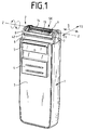
- FIG. 1 shows an electric shaver with a housing 1 and a shaving head system 2 which can be pivoted about a pivot axis Z relative to the housing 1, and an on / off switch 4 which is displaceably mounted on the front side 3 and to which a displaceably mounted long hair cutter 5 is assigned.
- the two shaving head system 2 which runs parallel to one another and has an elongated design, consists of a shaving head frame 6 arranged on the housing 1, an upper knife 9 pivotably mounted between the end walls 7, 8 about the pivot axis Z, and - see FIG. 3 - two on the upper knife 9 adjacent lower knives 15, 16, which are coupled via a coupling element 11 to a drive system 12 arranged in the housing 1 both in terms of drive and pivotable about the pivot axis Z, the pivoting movement of the lower knives 15, 16 due to the action of the pivotably mounted upper knife 9 on the lower knives 15, 16 is effected.
- the shaving head frame 6 is removably attached to the housing 1 by means of a locking device.
- Upper knife frame 42 and shaving head frame 6 - see FIG. 2 - are coupled to one another via their front side walls 8 and 45 and 7 and 41 by means of bearing bolts 50, 51 passing through bearing bores 46, 47, 48, 49 and fastening of the bearing bolts 50, 51 serving for holding plates 56.
- the center axis of the bearing bolts 50, 51 lies on the pivot axis Z.
- the upper knife 9 which forms the two shaving heads SK with the lower knives 15, 16 has two curved shear surfaces 13, 14 which run parallel to the pivot axis Z.
- the tangential plane connecting the arcuate shear surfaces 13 and 14 is an imaginary plane which is referred to as the shear plane SE - see FIG. 1a.
- the shear surfaces 13 and 14 are formed by two shaving foils 131, 141 that are arched in the upper knife frame 42.
- Each of the two shaving foils 131 and 141 is fastened to a web 421 provided inside the upper knife frame 42 and extending parallel to the pivot axis Z, and is coupled to the opposite longitudinal side in each case with one of the two side walls 422, 423 of the upper knife frame 42 also running parallel to the pivot axis.
- the lower knives 15, 16 consist of two arcuate knife blocks which run parallel to one another and are arranged together on the coupling element 11.
- the drive system 12 consists of a swing bridge 27 arranged in the housing 1, driven by a motor 25 by means of an eccentric 26, and coupling elements arranged on the swing bridge 27, such as a support plate 100 with fastening hooks 28, 29, by means of which a drive element 30 and a fastening hook 31, 32 having coupling sleeve 33 are attached to the support plate 100 via corresponding annular shoulders 34, 35.
- the drive element 30 consists of a drive sleeve. At the end facing the lower cutters 15, 16, the drive sleeve 30 has a cylinder pot 36 with an annular outer bead 37 which is provided with a shape corresponding to a spherical cutout.
- the outer bead 37 is in contact with the inner sides of the inner walls 17 and 18 and, on the one hand, ensures a transmission of the oscillating movement of the oscillating bridge 27 via the coupling element 11 to the lower knives 15, 16 and a pivoting movement enabling the lower cutters 15, 16 to be mounted on the drive sleeve 30.
- a pressure ram 38 passing through the cylinder pot 36 is arranged in the cup-shaped drive sleeve 30.
- the drive sleeve 30 surrounding coupling sleeve 33 engages with the fastening hooks 31 and 32 over the webs 22 and 23 provided on the outer walls 20, 21 of the coupling element 11, with a predetermined flexibility of the fastening hooks 31 and 32 making coupling and decoupling easy and easy to use at all times Lower knife 15, 16 with the coupling element 11 is guaranteed by the drive system.
- the fastening hooks 28, 29 are likewise designed to be flexible and thus simplify the assembly and disassembly of the pressure ram 38, spring 40, drive sleeve 30 and coupling sleeve 33 on the swing bridge 27.
- Fig. 3 shows a section through a shaving head frame 6, upper knife frame 42, lower knife 15, 16 and coupling element 11 and coupling sleeve 33 placed on the housing 1, the section running through the fastening hook 31 of the coupling sleeve 33 and the web 22 of the coupling element 11.
- a latching cam 311 is provided on the latching hook 31. In the assembled state of the housing 1, the shaving head frame 6 and the upper knife frame 42, the latching cam 311 of the latching hook 31 is at a distance above the web 22 provided with a control curve 221 and a recess 222.
- the distance A is established during the assembly of the shaving head frame 6 on the Housing 1 automatically on, since the two lower knives 15, 16 arranged on the coupling element 11 are moved in the vertical direction downward via the associated shaving foils 131, 141 during assembly against the pressure of the pressure plunger 38 acted upon by the spring 40.
- Fig. 3a shows the partial section through the razor of FIG. 3 with a shaving head frame 6 removed from the housing 1.
- the removal of the shaving head frame 6 from the housing 1 has the result that it rests against the wall 241 of the coupling element 11 under the pressure of the spring 40 Pressure plunger 38 moves upwards in the vertical direction V until, depending on the respective pivoting position of the lower cutters 15, 16, the locking cams 311 follow Travel distance A to the system on control cam 221. Thereafter, the control cam 221 slides along the locking cam 311 using the spring tension of the spring 40 until the locking cam 311 snaps into the recess 222 provided in the control cam 221.
- the recess 222 is provided in the middle of the arc-shaped control cam 221, whereby after the latching cam 311 has snapped into the recess 222, the lower knife 10 assumes a centering position which is in and against the center of the predetermined pivoting range the clockwise pivotable lower knife 10 is.
- a control curve with a prismatic control surface, the prism surfaces of which open into a recess can also be provided - not shown.
- the web 23 of the coupling element 11 and the second fastening hook 32 provided on the coupling sleeve 33 are designed in accordance with the previously described web 22 and fastening hook 31 and are provided offset by 180.degree.
- the lower knives 15, 16 with the coupling piece 11 and the pressure plunger 38 are moved downwards against the pressure of the spring 40 in the vertical direction, the through knife Locking cams 311, the fastening hooks 31 and 32 and the recesses 222 in the cam 221 locking formed inevitably is canceled, as shown in Fig. 3.
- the lower knives 15, 16 together with the upper knife 9 can carry out a back and forth swiveling movement about the swiveling axis Z.
- a bearing rod 110 is fastened transversely to the direction of vibration S of the lower knives 15, 16 or transversely to the axial direction of the pivot axis Z.
- the lower knife 16 is mounted to move back and forth in the arrow directions F 1 and F 2, a sliding element 117 being slidably arranged on the bearing rod 110 being provided between a carrier carrying the knife blades of the lower knife and the coupling element 11.
- a downwardly extending holding element 118 is provided on the sliding element 117, which projects into a U-shaped recess 116 embedded in the coupling element 11.
- the extending into the recess 116 side walls of the holding member 118 serve as a stop 113 and 115 to limit the sliding movement of the lower knife 16 on the bearing rod 110.
- the sliding path of the lower knife 16 on the bearing rod 110 in the direction of arrow F1 or F2 is by the respective stops 112th and 114, which are formed in the exemplary embodiment shown by the side walls of the U-shaped recess 116.
- the lower knife 16 is mounted on the bearing rod 110 in the direction of the arrow when the stop 113 is in contact with the stop 112 by the distance B which the stops 114 and 115 are in relation to one another .
- the distance C that the stops 114 and 112 to each other, is dimensioned such that in a shaving head frame 6 placed on the housing 1 - see FIG. 3 - there is a gap between the stops 113 and the stop 112.
- Such a dimensioning of the distance C ensures, due to the movable mounting of the lower knife 16 on the bearing rod 110, an optimal adaptation of the lower knife 16 to the shaving foil 131 of the upper knife 9.
- both lower knives 15, 16 are slidably arranged on the bearing rod 110 in the arrow directions F1 and F2.
- the bearing rod 110 can be fastened, for example, in a wall provided on the coupling element 11 between the lower cutters 15 and 16, the stops limiting the sliding movement of the lower cutters 15 and 16 on the one hand by holding elements formed on the sliding elements of the lower cutters and on the other hand by the side walls of U. -shaped recesses, which are provided on both sides of the wall holding the bearing rod in the coupling element.
- the shaving head frame 6, which is detachably coupled to the housing 1, is equipped with an upper knife 9, which forms two shaving heads SK and is fixed immovably in the shaving head frame.
- the two lower knives are coupled via the coupling element 11 to the drive element 30 of the drive system 12 only for the transmission of the oscillating movement S, as a result of which all constructive measures serving to transmit a pivoting movement of the upper knife and the lower knife about the pivot axis Z are omitted.
- On the coupling element 11, at least one of the lower knives 15, 16 is movably mounted on a slide rod, which was described above, in the arrow directions F 1 and F 2.
Landscapes
- Life Sciences & Earth Sciences (AREA)
- Forests & Forestry (AREA)
- Engineering & Computer Science (AREA)
- Mechanical Engineering (AREA)
- Dry Shavers And Clippers (AREA)
- Reverberation, Karaoke And Other Acoustics (AREA)
- Finish Polishing, Edge Sharpening, And Grinding By Specific Grinding Devices (AREA)
Applications Claiming Priority (2)
| Application Number | Priority Date | Filing Date | Title |
|---|---|---|---|
| DE4128220A DE4128220C1 (fr) | 1991-08-26 | 1991-08-26 | |
| DE4128220 | 1991-08-26 |
Publications (2)
| Publication Number | Publication Date |
|---|---|
| EP0529406A1 true EP0529406A1 (fr) | 1993-03-03 |
| EP0529406B1 EP0529406B1 (fr) | 1995-12-20 |
Family
ID=6439114
Family Applications (1)
| Application Number | Title | Priority Date | Filing Date |
|---|---|---|---|
| EP92113717A Expired - Lifetime EP0529406B1 (fr) | 1991-08-26 | 1992-08-12 | Rasoir à sec |
Country Status (7)
| Country | Link |
|---|---|
| US (1) | US5245754A (fr) |
| EP (1) | EP0529406B1 (fr) |
| JP (1) | JPH05192455A (fr) |
| AT (1) | ATE131763T1 (fr) |
| DE (2) | DE4128220C1 (fr) |
| ES (1) | ES2082299T3 (fr) |
| HK (1) | HK92296A (fr) |
Cited By (2)
| Publication number | Priority date | Publication date | Assignee | Title |
|---|---|---|---|---|
| CN109789580A (zh) * | 2016-09-28 | 2019-05-21 | 博朗有限公司 | 剃刀耦接头和具有耦接头的电动剃刀 |
| US11331821B2 (en) | 2016-09-28 | 2022-05-17 | Braun Gmbh | Electrically driven device |
Families Citing this family (9)
| Publication number | Priority date | Publication date | Assignee | Title |
|---|---|---|---|---|
| DE4303972C1 (de) * | 1993-02-11 | 1993-10-14 | Braun Ag | Trockenrasierapparat mit einem schwenkbar gelagerten Scherkopfsystem |
| JP3716353B2 (ja) * | 1995-07-31 | 2005-11-16 | 九州日立マクセル株式会社 | ロータリ式電気かみそり |
| US6826835B1 (en) | 2003-09-05 | 2004-12-07 | Raymond Electric (China) Ltd. | Electric shaver |
| DE102006034050A1 (de) * | 2006-07-20 | 2008-01-24 | Braun Gmbh | Elektrischer Rasierapparat |
| DE102008045934B4 (de) | 2008-09-04 | 2010-06-10 | Braun Gmbh | Antrieb für einen Rasierer |
| US8720072B2 (en) | 2010-08-11 | 2014-05-13 | Thomas J. Bucco | Razor with three-axis multi-position capability |
| EP2591889B1 (fr) * | 2011-11-08 | 2015-09-16 | Braun GmbH | Rasoir électrique comportant une tête de rasage pivotante |
| US20170173804A1 (en) * | 2015-12-17 | 2017-06-22 | Troy Patrick Worth | Opposed dual foil shaving heads and trimmer |
| JP2022155347A (ja) * | 2021-03-30 | 2022-10-13 | パナソニックIpマネジメント株式会社 | 電気かみそり |
Citations (5)
| Publication number | Priority date | Publication date | Assignee | Title |
|---|---|---|---|---|
| DE2236276A1 (de) * | 1971-07-27 | 1973-02-15 | Gillette Co | Batteriegetriebener trockenrasierer |
| US4219930A (en) * | 1978-07-07 | 1980-09-02 | Remington Products, Inc. | Cutter head assembly for an electric dry shaver |
| GB2214124A (en) * | 1988-01-26 | 1989-08-31 | Matsushita Electric Works Ltd | A cutting head for reciprocating-type dry shavers |
| DE3926894C1 (fr) * | 1989-08-16 | 1990-12-06 | Braun Ag, 6000 Frankfurt, De | |
| EP0486903A1 (fr) * | 1990-11-23 | 1992-05-27 | Wahl Clipper Corporation | Rasoir électrique avec support flexible de couteau |
Family Cites Families (5)
| Publication number | Priority date | Publication date | Assignee | Title |
|---|---|---|---|---|
| US4292737A (en) * | 1978-12-11 | 1981-10-06 | The Gillette Company | Dry shaver with differentially biased inner cutter and base members |
| DE3610736A1 (de) * | 1986-03-29 | 1987-10-01 | Braun Ag | Elektrischer rasierapparat mit einem schwenkbaren scherkopfsystem |
| GB8626631D0 (en) * | 1986-11-07 | 1986-12-10 | Gillette Co | Dry shavers |
| JPS63174685A (ja) * | 1987-01-14 | 1988-07-19 | 松下電工株式会社 | 電気かみそりのトリマ−装置 |
| DE3726354A1 (de) * | 1987-08-07 | 1989-02-16 | Braun Ag | Elektrischer rasierapparat mit scherkopfsteuerung |
-
1991
- 1991-08-26 DE DE4128220A patent/DE4128220C1/de not_active Expired - Fee Related
-
1992
- 1992-08-12 ES ES92113717T patent/ES2082299T3/es not_active Expired - Lifetime
- 1992-08-12 EP EP92113717A patent/EP0529406B1/fr not_active Expired - Lifetime
- 1992-08-12 DE DE59204737T patent/DE59204737D1/de not_active Expired - Fee Related
- 1992-08-12 AT AT92113717T patent/ATE131763T1/de not_active IP Right Cessation
- 1992-08-18 US US07/931,583 patent/US5245754A/en not_active Expired - Fee Related
- 1992-08-26 JP JP4227316A patent/JPH05192455A/ja active Pending
-
1996
- 1996-05-30 HK HK92296A patent/HK92296A/xx not_active IP Right Cessation
Patent Citations (5)
| Publication number | Priority date | Publication date | Assignee | Title |
|---|---|---|---|---|
| DE2236276A1 (de) * | 1971-07-27 | 1973-02-15 | Gillette Co | Batteriegetriebener trockenrasierer |
| US4219930A (en) * | 1978-07-07 | 1980-09-02 | Remington Products, Inc. | Cutter head assembly for an electric dry shaver |
| GB2214124A (en) * | 1988-01-26 | 1989-08-31 | Matsushita Electric Works Ltd | A cutting head for reciprocating-type dry shavers |
| DE3926894C1 (fr) * | 1989-08-16 | 1990-12-06 | Braun Ag, 6000 Frankfurt, De | |
| EP0486903A1 (fr) * | 1990-11-23 | 1992-05-27 | Wahl Clipper Corporation | Rasoir électrique avec support flexible de couteau |
Cited By (2)
| Publication number | Priority date | Publication date | Assignee | Title |
|---|---|---|---|---|
| CN109789580A (zh) * | 2016-09-28 | 2019-05-21 | 博朗有限公司 | 剃刀耦接头和具有耦接头的电动剃刀 |
| US11331821B2 (en) | 2016-09-28 | 2022-05-17 | Braun Gmbh | Electrically driven device |
Also Published As
| Publication number | Publication date |
|---|---|
| ES2082299T3 (es) | 1996-03-16 |
| DE4128220C1 (fr) | 1992-08-06 |
| DE59204737D1 (de) | 1996-02-01 |
| US5245754A (en) | 1993-09-21 |
| JPH05192455A (ja) | 1993-08-03 |
| ATE131763T1 (de) | 1996-01-15 |
| EP0529406B1 (fr) | 1995-12-20 |
| HK92296A (en) | 1996-06-07 |
Similar Documents
| Publication | Publication Date | Title |
|---|---|---|
| DE69221907T2 (de) | Trockenrasierapparat | |
| EP2315649B1 (fr) | Petit appareil électrique pour enlever les poils | |
| DE19543095C1 (de) | Trockenrasierapparat | |
| DE4244164C2 (de) | Trockenrasierapparat mit einem schwenkbar gelagerten Langhaarschneider | |
| DE4313371C2 (de) | Trockenrasierapparat | |
| EP0693988B1 (fr) | Tete de rasage pour rasoirs electriques | |
| DE69517497T2 (de) | Elektrischer Rasierapparat | |
| EP1641601B1 (fr) | Tondeuse electrique | |
| DE2558783C2 (de) | Gerät mit einem von einem elektromotorischen Antrieb her antreibbaren Geräteteil | |
| EP0529406B1 (fr) | Rasoir à sec | |
| EP2035194B1 (fr) | Unité de cisaillement pour rasoir électrique | |
| DE69433024T2 (de) | Schneidvorrichtungen für elektrische Haarschneidemaschine | |
| EP0532904B1 (fr) | Appareil de rasage à sec | |
| DE4128219C2 (fr) | ||
| DE4132844C2 (de) | Schneidkopfanordnung für Haarschneider | |
| DE2309342C2 (de) | Scherkopf für Trockenrasierapparate | |
| DE69106674T2 (de) | Elektrisches Rasiergerät mit einer flexiblen Schneiderhalterung. | |
| DE3926894C1 (fr) | ||
| EP0478704B1 (fr) | Cadre articule pour rasoir electrique | |
| DE2236276A1 (de) | Batteriegetriebener trockenrasierer | |
| EP0673728A1 (fr) | Rasoir à sec avec verrouillage du cadre portant la feuille perforée coupante | |
| EP0476326B1 (fr) | Cadre de changement pour rasoir à sec | |
| DE1553814C3 (de) | Elektrisches Trockenrasiergerät | |
| DE69308754T2 (de) | Rasiergerät mit einem folienartigen Ober- und Untermesser | |
| DE10302998A1 (de) | Schneidsatz für Haarschneidemaschinen |
Legal Events
| Date | Code | Title | Description |
|---|---|---|---|
| PUAI | Public reference made under article 153(3) epc to a published international application that has entered the european phase |
Free format text: ORIGINAL CODE: 0009012 |
|
| AK | Designated contracting states |
Kind code of ref document: A1 Designated state(s): AT CH DE ES FR GB IT LI NL |
|
| 17P | Request for examination filed |
Effective date: 19930331 |
|
| 17Q | First examination report despatched |
Effective date: 19941021 |
|
| ITF | It: translation for a ep patent filed | ||
| RAP1 | Party data changed (applicant data changed or rights of an application transferred) |
Owner name: BRAUN AKTIENGESELLSCHAFT |
|
| GRAA | (expected) grant |
Free format text: ORIGINAL CODE: 0009210 |
|
| AK | Designated contracting states |
Kind code of ref document: B1 Designated state(s): AT CH DE ES FR GB IT LI NL |
|
| REF | Corresponds to: |
Ref document number: 131763 Country of ref document: AT Date of ref document: 19960115 Kind code of ref document: T |
|
| GBT | Gb: translation of ep patent filed (gb section 77(6)(a)/1977) |
Effective date: 19960102 |
|
| REF | Corresponds to: |
Ref document number: 59204737 Country of ref document: DE Date of ref document: 19960201 |
|
| REG | Reference to a national code |
Ref country code: CH Ref legal event code: NV Representative=s name: PATENTANWALTSBUREAU BOSSHARD UND LUCHS |
|
| REG | Reference to a national code |
Ref country code: ES Ref legal event code: FG2A Ref document number: 2082299 Country of ref document: ES Kind code of ref document: T3 |
|
| ET | Fr: translation filed | ||
| PGFP | Annual fee paid to national office [announced via postgrant information from national office to epo] |
Ref country code: ES Payment date: 19960819 Year of fee payment: 5 |
|
| PGFP | Annual fee paid to national office [announced via postgrant information from national office to epo] |
Ref country code: CH Payment date: 19961004 Year of fee payment: 5 |
|
| PLBE | No opposition filed within time limit |
Free format text: ORIGINAL CODE: 0009261 |
|
| 26N | No opposition filed | ||
| PG25 | Lapsed in a contracting state [announced via postgrant information from national office to epo] |
Ref country code: ES Free format text: LAPSE BECAUSE OF THE APPLICANT RENOUNCES Effective date: 19970813 |
|
| PG25 | Lapsed in a contracting state [announced via postgrant information from national office to epo] |
Ref country code: LI Free format text: LAPSE BECAUSE OF NON-PAYMENT OF DUE FEES Effective date: 19970831 Ref country code: CH Free format text: LAPSE BECAUSE OF NON-PAYMENT OF DUE FEES Effective date: 19970831 |
|
| REG | Reference to a national code |
Ref country code: CH Ref legal event code: PL |
|
| REG | Reference to a national code |
Ref country code: FR Ref legal event code: CA Ref country code: FR Ref legal event code: CD |
|
| REG | Reference to a national code |
Ref country code: ES Ref legal event code: FD2A Effective date: 20001102 |
|
| REG | Reference to a national code |
Ref country code: GB Ref legal event code: IF02 |
|
| PGFP | Annual fee paid to national office [announced via postgrant information from national office to epo] |
Ref country code: AT Payment date: 20040820 Year of fee payment: 13 Ref country code: FR Payment date: 20040820 Year of fee payment: 13 |
|
| PGFP | Annual fee paid to national office [announced via postgrant information from national office to epo] |
Ref country code: NL Payment date: 20040826 Year of fee payment: 13 |
|
| PG25 | Lapsed in a contracting state [announced via postgrant information from national office to epo] |
Ref country code: IT Free format text: LAPSE BECAUSE OF NON-PAYMENT OF DUE FEES;WARNING: LAPSES OF ITALIAN PATENTS WITH EFFECTIVE DATE BEFORE 2007 MAY HAVE OCCURRED AT ANY TIME BEFORE 2007. THE CORRECT EFFECTIVE DATE MAY BE DIFFERENT FROM THE ONE RECORDED. Effective date: 20050812 Ref country code: AT Free format text: LAPSE BECAUSE OF NON-PAYMENT OF DUE FEES Effective date: 20050812 |
|
| PG25 | Lapsed in a contracting state [announced via postgrant information from national office to epo] |
Ref country code: NL Free format text: LAPSE BECAUSE OF NON-PAYMENT OF DUE FEES Effective date: 20060301 |
|
| PG25 | Lapsed in a contracting state [announced via postgrant information from national office to epo] |
Ref country code: FR Free format text: LAPSE BECAUSE OF NON-PAYMENT OF DUE FEES Effective date: 20060428 |
|
| NLV4 | Nl: lapsed or anulled due to non-payment of the annual fee |
Effective date: 20060301 |
|
| REG | Reference to a national code |
Ref country code: FR Ref legal event code: ST Effective date: 20060428 |
|
| PGFP | Annual fee paid to national office [announced via postgrant information from national office to epo] |
Ref country code: GB Payment date: 20060724 Year of fee payment: 15 |
|
| PGFP | Annual fee paid to national office [announced via postgrant information from national office to epo] |
Ref country code: DE Payment date: 20070802 Year of fee payment: 16 |
|
| GBPC | Gb: european patent ceased through non-payment of renewal fee |
Effective date: 20070812 |
|
| PG25 | Lapsed in a contracting state [announced via postgrant information from national office to epo] |
Ref country code: GB Free format text: LAPSE BECAUSE OF NON-PAYMENT OF DUE FEES Effective date: 20070812 |
|
| PG25 | Lapsed in a contracting state [announced via postgrant information from national office to epo] |
Ref country code: DE Free format text: LAPSE BECAUSE OF NON-PAYMENT OF DUE FEES Effective date: 20090303 |