EP0529438B1 - Dispositif pour séparer et enlever une feuille d'un matériau support laminé - Google Patents
Dispositif pour séparer et enlever une feuille d'un matériau support laminé Download PDFInfo
- Publication number
- EP0529438B1 EP0529438B1 EP92113894A EP92113894A EP0529438B1 EP 0529438 B1 EP0529438 B1 EP 0529438B1 EP 92113894 A EP92113894 A EP 92113894A EP 92113894 A EP92113894 A EP 92113894A EP 0529438 B1 EP0529438 B1 EP 0529438B1
- Authority
- EP
- European Patent Office
- Prior art keywords
- film
- gap
- separating
- plate
- carrier material
- Prior art date
- Legal status (The legal status is an assumption and is not a legal conclusion. Google has not performed a legal analysis and makes no representation as to the accuracy of the status listed.)
- Expired - Lifetime
Links
Images


Classifications
-
- B—PERFORMING OPERATIONS; TRANSPORTING
- B26—HAND CUTTING TOOLS; CUTTING; SEVERING
- B26D—CUTTING; DETAILS COMMON TO MACHINES FOR PERFORATING, PUNCHING, CUTTING-OUT, STAMPING-OUT OR SEVERING
- B26D3/00—Cutting work characterised by the nature of the cut made; Apparatus therefor
- B26D3/28—Splitting layers from work; Mutually separating layers by cutting
- B26D3/282—Splitting layers from work; Mutually separating layers by cutting by peeling-off
-
- G—PHYSICS
- G03—PHOTOGRAPHY; CINEMATOGRAPHY; ANALOGOUS TECHNIQUES USING WAVES OTHER THAN OPTICAL WAVES; ELECTROGRAPHY; HOLOGRAPHY
- G03F—PHOTOMECHANICAL PRODUCTION OF TEXTURED OR PATTERNED SURFACES, e.g. FOR PRINTING, FOR PROCESSING OF SEMICONDUCTOR DEVICES; MATERIALS THEREFOR; ORIGINALS THEREFOR; APPARATUS SPECIALLY ADAPTED THEREFOR
- G03F7/00—Photomechanical, e.g. photolithographic, production of textured or patterned surfaces, e.g. printing surfaces; Materials therefor, e.g. comprising photoresists; Apparatus specially adapted therefor
- G03F7/16—Coating processes; Apparatus therefor
- G03F7/161—Coating processes; Apparatus therefor using a previously coated surface, e.g. by stamping or by transfer lamination
-
- Y—GENERAL TAGGING OF NEW TECHNOLOGICAL DEVELOPMENTS; GENERAL TAGGING OF CROSS-SECTIONAL TECHNOLOGIES SPANNING OVER SEVERAL SECTIONS OF THE IPC; TECHNICAL SUBJECTS COVERED BY FORMER USPC CROSS-REFERENCE ART COLLECTIONS [XRACs] AND DIGESTS
- Y10—TECHNICAL SUBJECTS COVERED BY FORMER USPC
- Y10T—TECHNICAL SUBJECTS COVERED BY FORMER US CLASSIFICATION
- Y10T156/00—Adhesive bonding and miscellaneous chemical manufacture
- Y10T156/19—Delaminating means
- Y10T156/1978—Delaminating bending means
- Y10T156/1983—Poking delaminating means
-
- Y—GENERAL TAGGING OF NEW TECHNOLOGICAL DEVELOPMENTS; GENERAL TAGGING OF CROSS-SECTIONAL TECHNOLOGIES SPANNING OVER SEVERAL SECTIONS OF THE IPC; TECHNICAL SUBJECTS COVERED BY FORMER USPC CROSS-REFERENCE ART COLLECTIONS [XRACs] AND DIGESTS
- Y10—TECHNICAL SUBJECTS COVERED BY FORMER USPC
- Y10T—TECHNICAL SUBJECTS COVERED BY FORMER US CLASSIFICATION
- Y10T156/00—Adhesive bonding and miscellaneous chemical manufacture
- Y10T156/19—Delaminating means
- Y10T156/1978—Delaminating bending means
- Y10T156/1989—Corner edge bending delaminating means
Definitions
- the invention relates to a device and a method for separating and peeling off a film laminated onto a carrier material, having a horizontal base plate and a plate partially arranged above it and having a pull-off edge, the base plate and the plate arranged above forming a first gap.
- this separating device has a wedge-shaped separating knife and an overlying element, which forms a parallel second gap with the separating knife, and can be moved back and forth over the laminate of film and carrier material lying on the base plate. Furthermore, the separating device can be displaced in the vertical direction with respect to the base plate.
- Photosensitive layers or layers such as, for example, exposed photoresist layers on printed circuit boards or color proofing foils, are generally covered by protective foils.
- a substrate is first coated with a light-sensitive material. Then the material is covered with a transparent film. This laminate of film and light-sensitive layer is then exposed imagewise through a mask. This exposure causes an image-forming, different adhesion of the photosensitive layer in such a way that the exposed parts adhere to the substrate with a stronger adhesion than the unexposed parts. If the protective film and the substrate are separated from one another, there is, for example, a positive image on the substrate and a negative image on the protective film.
- the substrate is laminated with a photosensitive dry-resist film.
- a Imaging mask representing the electrical circuit is exposed to the dry resist film and then the protective film is removed and the dry resist film is developed in various processing steps.
- the protective film on the dry resist film enables a largely dust-free exposure and the transport of the coated printed circuit boards in the stacked state.
- the circuit boards have in particular one or more edges which are free of the laminated protective film, so that the plate can be gripped by gripping tools or manually at these free edges.
- the coated substrate and a receiver sheet placed thereon are passed under pressure through a laminating nip of heated laminating rollers.
- the substrate and the receiver sheet are then separated from one another and the colored resin layer is transferred from the substrate to the receiver sheet.
- a problem with such transfer methods is the incompleteness of transfer of the colored resin layer.
- U.S. Patent 4,752,346 describes an apparatus and method for peeling and separating adhered ones Foils.
- the device comprises a platform made of a metal or of a material, the surface of which is provided with an electrically conductive layer.
- the ledge edge is positioned above the platform using supports at each end of the ledge edge.
- the supports which are surrounded by springs, are led through the ledge edge and protrude above it. It is thus possible for a variable gap to form between the underside of the ledge edge and the surface of the platform, which enables laminates of substrate and film of different thickness to be passed between the ledge edge and the surface of the platform.
- a colored photosensitive layer which is covered by a receiver sheet, is applied to a transparent polyester film by means of an adhesive layer.
- This sandwich arrangement passes through the nip of laminating rollers and is then inserted between the ledge edge and the platform of the take-off device.
- the transparent polyester film is peeled off over the edge of the ledge by folding the film over the edge angle upwards along the slope of the ledge edge.
- the polyester film is separated from the receiver sheet or the receiver film and the adhesive and colored photosensitive layers are transferred to the receiver sheet.
- the device for carrying out the method comprises a transport and adjustment device, by means of which the plate-shaped body can be pivoted from its transport direction into a working position, furthermore a device for applying a double-sided adhesive element which is pliers-shaped and has plate-shaped bodies for receiving bearing rollers and a device for removing the adhesive element and the protective film of the plate-shaped body connected thereto.
- This device has roller systems arranged axially parallel with a device for keeping the roller spacing constant.
- the object of the invention is to remedy this situation and to propose a device and a method in which a reliable complete and fully automatic removal of a film from without adhesive tape or adhesive element a carrier material on which one or more photosensitive layers are applied.
- a separating device along a spindle with the help of a motor can be moved back and forth over the laminate of film and carrier material lying on the base plate, up to and over the plate, whereby the separating device is displaceable in the vertical direction relative to the base plate in such a way that the separating device has a wedge-shaped separating knife and an element above it which forms a parallel second gap with the obliquely inclined to the horizontal inclined upper side of the separating knife, by means of a pressure roller which is designed as a separating knife head Element is arranged above the second gap and can be moved back and forth on the inclined upper side of the separating knife, a film corner threaded into the second gap can be clamped, and that the laminate can be moved back and forth by means of a stamp that can be moved back and forth, which penetrates the base plate vertically, can be clamped in the first gap.
- the separating device is attached to the underside of an angular frame, in the vertical leg of which a roller is rotatably mounted at the lower end.
- the separating knife forms the underside of this gap, which encloses an angle in the range from 5 to 25 °, in particular from 10 to 20 °, in the feed direction of the separating device with the horizontal.
- the object is also achieved by a method according to claim 13.
- the method for separating and peeling off a film laminated on a carrier material, the laminate of film and carrier material being placed on a horizontal base plate and aligned with its diagonals in a feed direction of a separating device running parallel to the base plate, is that, separated by a first one Gap, a plate is arranged above the base plate so that at least one film corner of the laminate freely movable in the first gap is not covered by the plate, that the laminate is clamped in the first gap and the film corner due to a feed movement of the separating device with the aid of a wedge-shaped separating knife the separating device is detached from the carrier material and is threaded into a second slit, which runs obliquely to the horizontal and lies above the separating knife, so that the clamped laminate is released and the film corner is self-adhesive during a further feed movement mmend is held in the second gap and an additional clamping pressure is exerted on the film corner, which supports the self-clamping of the film corner threaded into the
- the additional clamping pressure on the film corner in the second gap primarily serves to adequately hold large-format laminates and / or thin carrier materials that do not fully fill the second gap due to their small thickness.
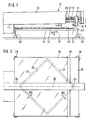
- a device 31 for separating and peeling a film 22 from a carrier material 21 is shown schematically in side view.
- the device 31 consists of a base plate 15, which is divided into four Legs 29 are supported at the corners of the base plate, a transparent plate 16, a spindle 12 driven by a motor, which is arranged opposite a guide 11, on which a separating device 10 is seated and can be moved back and forth over the base plate 15, as is the case the double arrow A shows and a stamp 17, which passes through the base plate 15 and can be raised and lowered, as indicated by the double arrow B.
- the transparent plate 16 is arranged above the base plate 15 at a certain distance and has a bevel 25.
- the carrier material 21 with the laminated film 22 is inserted.
- the plate 16 does not completely cover the base plate 15, as can be seen from FIGS. 1 and 2, but is shorter than the base plate 15 in the feed direction of the separating device 10.
- the plate 16 consists of a transparent material, for example glass or plastic, with glass being preferred.
- the carrier material 21 can be a film on which, for example, a colored, light-sensitive synthetic resin layer is applied.
- the film 22 laminated above then serves as a receiving film for this colored synthetic resin layer, which is generally a polymer layer with an appropriate dye.
- the colored synthetic resin layer is then transferred from the carrier material to the receiving film 22. After that the exposure of this color test film thus obtained can then take place.
- a printed circuit board with an exposed photoresist pattern can also be used as the carrier material 21, and the film 22 is then a protective film for the exposed photoresist pattern. After the circuit board has been exposed, the protective film is removed and the photoresist pattern is developed in various baths. The protective film must be removed without causing damage to the photoresist pattern and / or without residues of the protective film remaining on the photoresist film.
- the film 22 is laminated onto the carrier material 21 in such a way that edges 32 of the carrier material 21 remain free of the laminated film 22 all around.
- the laminate 23 made of the carrier material 21 and the film 22 is arranged between the base plate 15 and the plate 16 such that the diagonal 26 of the rectangular or square laminate is aligned in the feed direction of the separating device 10.
- a film corner 24 of the film 22 lies on the diagonal 26.
- the separating device 10 has a wedge-shaped separating knife 13, above which there is a gap 14 which runs parallel to it and which is inclined obliquely to the horizontal with the same inclination as the upper surface of the wedge-shaped separating knife.
- two positions of the separating device 10 are shown in the feed direction. In the first, left-hand position, shown in dash-dot lines, the separating device 10 and thus the separating knife 13 are located just before the film corner 24; the film corner 24 is not yet detached from the carrier material 21 at this time.
- the separating device 10 is fastened to the underside of an angular frame 18 which has a horizontal and vertical leg.
- a roller 20 is rotatably mounted at the lower end, which initially rolls over the laminate 23 during the feed.
- the wedge-shaped separating knife 13 has detached the film corner 24 of the film 22 from the carrier material 21 and threaded this film corner 24 into the gap 14.
- the roller 20 is then located directly on the front, ie at the beginning of the bevel 25 of the plate 16.
- the stamp 17, which penetrates the base plate 15 vertically, presses the laminate 23 against the underside of the plate 16 in this position of the separating device 10 and holds it it it firmly so that the detached film corner 24 can be threaded into the gap 14 without difficulty.
- the stamp 17 can be raised or lowered pneumatically or hydraulically. The pneumatic required for this or hydraulic device is known in the prior art and is therefore not shown in the drawing.
- the separating knife 13 forms, as it were, the underside of the gap 14, which includes an angle in the range from 5 to 25 °, in particular from 10 to 20 ° in the feed direction of the separating device 10 with the horizontal. In a special embodiment, the angle of the gap with the horizontal is 15 °.
- the gap length is equal to or greater than 20 mm. In particular, a gap length of 30 mm has proven to be favorable in tests.
- the film corner 24 is generally threaded up to 20 mm into the gap. As the separating device continues to advance, the threaded film corner 24 is held in a self-locking manner by the separating knife 13 in the gap.
- FIG. 4 shows a position of the separating device 10, in which the roller 20 moves up on the bevel 25 of the plate 16 and thereby the separating device 10 lifts off the laminate 23 on the base plate 15.
- the separating device 10 can be displaced in the vertical direction with respect to the base plate 15.
- the film 22 is folded around the front edge or around the start edge of the bevel 25 and threaded into the gap 14 of the separating device 10 with a further, opposite kink.
- the laminate 23 no longer held by the stamp 17, which is lowered down.
- FIG. 5 shows a position of the separating device 10 in which it moves along the surface of the plate 16.
- the angle ⁇ of the wedge-shaped separating knife 13 is in the previously specified angular range for the gap 14, or has the same size of 15 ° as the above-mentioned preferred exemplary embodiment for the gap 14.
- the roller 20 is from the top of the plate 16 lifted, which is due to the fact that the lowest point of the roller 20, as can be seen for example from Figure 5, lies above the plane of the horizontal surface of the wedge-shaped cutting knife 13. This measure is necessary so that the separating knife 13 can easily detach the film corner 24 from the carrier material 21.
- the stamp 17 is lowered and has no contact with the underside of the laminate or the carrier material.
- the direction of advance of the separating device 10 is indicated by the arrow C in FIGS. 3 to 5.
- the separation and removal of the film from the carrier material proceeds as follows:
- the laminate 23, consisting of the film 22 and the carrier material 21, is placed diagonally between the base plate 15 and the plate 16 lying a short distance above it, which has the bevel 25 on the inlet side, inserted.
- the laminate 23 is held on the underside by the stamp 17.
- the upper film 22 to be peeled is measured diagonally approximately 2 cm behind the front edge of the carrier material 21, ie in other words the edge 32 of the carrier material 21 which is left free by the film 22 is 2 cm.
- the film corner 24 of the film 22 pushes approximately 20 mm into the gap 14 located above the separating knife 13.
- the stamp 17 which fixes the laminate 23 from the underside is returned to its starting position and releases the laminate.
- the separating knife 13 then runs upwards from the roller 20, over the slope 25 located on the front of the plate 16.
- the film 22 located in the gap 14 above the separating knife 13 is bent at an angle of 5 to 20 °, in particular of 15 °, and there is a self-clamping hold between the separating knife 13 and the film 22 in the gap 14.
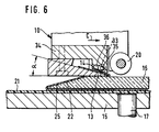
- a pressure roller 33 is shown, which is mounted with its axis ends 35 in parallel elongated holes 36, touches the top of the wedge-shaped cutting knife 13 and rolls up and down along the top of the cutting knife during the reciprocating movement of the cutting device 10.
- the elongated holes 36 run in the cutting knife head 34 inclined to the oblique gap 14.
- the pressure roller 33 exerts a clamping pressure on the film corner threaded into the gap 14, which supports the self-clamping in the event that it is large-sized and correspondingly heavy laminates or thin Carrier materials that do not fill the oblique gap due to their small thickness and therefore only experience a weak self-clamping.
Landscapes
- Life Sciences & Earth Sciences (AREA)
- Forests & Forestry (AREA)
- Engineering & Computer Science (AREA)
- Mechanical Engineering (AREA)
- Physics & Mathematics (AREA)
- General Physics & Mathematics (AREA)
- Manufacturing Of Printed Circuit Boards (AREA)
Claims (15)
- Dispositif pour séparer et retirer une feuille (22) plaquée sur un matériau de support (21), comportant une plaque de base horizontale (15) et une plaque (16) disposée partiellement au-dessus et à distance de la plaque de base et possédant un bord de retrait, la plaque de base (15) et la plaque (16) disposée au-dessus d'elle définissant une première fente, caractérisé en ce qu'un dispositif de séparation (10) peut être déplacé en va-et-vient le long d'une broche (12) à l'aide d'un moteur (11), au-dessus du stratifié (23) déposé sur la plaque de base (15) et formé par la feuille (22) et le matériau de support (21), jusqu'au-dessus de la plaque (16), le dispositif de séparation (10) étant déplaçable dans une direction verticale par rapport à la plaque de base (15), que le dispositif de séparation (10) possède un couteau de séparation en forme de coin (13) et un élément (34) situé au-dessus de ce couteau et formant avec la face supérieure, disposée obliquement par rapport à l'horizontale, du couteau de séparation (13), une seconde fente parallèle (14), un coin (24) de la feuille, qui est enfilé dans la seconde fente (14), pouvant être en outre bloqué fermement par serrage à l'aide d'un galet de pression (33), qui est disposé dans l'élément (34) agencé en forme de tête de couteau de séparation, au-dessus de la seconde fente (14) et est déplaçable en va-et-vient sur la face supérieure oblique du couteau de séparation (13), et que le stratifié (23) peut être bloqué par serrage dans la première fente, pendant l'enfilage d'un coin détaché (24) de la feuille, au moyen d'un poinçon (17) déplaçable en va-et-vient et qui traverse verticalement la plaque de base (15).
- Dispositif selon la revendication 1, caractérisé en ce que le dispositif de séparation (10) est fixé à la face inférieure d'un cadre en forme de cornière (18), à l'extrémité inférieure de la branche verticale (19) duquel est monté, de manière à pouvoir tourner, un rouleau (20).
- Dispositif selon la revendication 1, caractérisé en ce que le couteau de séparation (13) forme la face inférieure de la fente (14), qui fait, avec l'horizontale, un angle situé dans la gamme de 5 à 25°, et notamment 10 à 20° dans la direction d'avance du dispositif de séparation.
- Dispositif selon la revendication 1, caractérisé par le fait que la longueur de la fente est supérieure/égale à 20 mm.
- Dispositif selon la revendication 4, caractérisé en ce que la longueur de la fente est égale à 30 mm.
- Dispositif selon la revendication 1, caractérisé en ce que les extrémités (35) de l'axe du galet de pression (33) sont tourillonnées dans des trous allongés (36) de la tête (34) du couteau de séparation, qui sont parallèles entre eux et inclinés par rapport à la fente oblique (14).
- Dispositif selon les revendications 1 et 2, caractérisé en ce que la face avant de la plaque (16), qui est tournée vers le dispositif de séparation (10), possède un biseau (25), sur lequel le dispositif de séparation (10) circule, au moyen du rouleau (20), en remontant sur la face supérieure de la plaque (16).
- Dispositif selon la revendication 1, caractérisé en ce que la plaque (16) est réalisée en un matériau transparent tel que du verre ou une matière plastique.
- Dispositif selon la revendication 1, caractérisé en ce que le poinçon (17) peut être soulevé et abaissé pneumatiquement ou hydrauliquement.
- Dispositif selon la revendication 1, caractérisé en ce que la feuille (22) plaquée sur le matériau de support (21) est une feuille colorée et que le stratifié (23) est disposé entre la plaque de base (15) et la plaque (16) de telle sorte que la diagonale (26) du stratifié rectangulaire ou carré (23) est dirigée dans la direction d'avance du dispositif de séparation (10).
- Dispositif selon la revendication 1, caractérisé en ce que le matériau de support (21) est une feuille.
- Dispositif selon la revendication 1, caractérisé en ce que le matériau de support (21) est une plaquette à circuits imprimés portant un modèle en résine photosensible exposé, et la feuille (22) est une feuille de protection.
- Procédé pour séparer et retirer une feuille (22) plaquée sur un matériau de support (21), selon lequel on applique le stratifié (23) formé de la feuille et du matériau de support sur une plaque de base horizontale (15) et on l'oriente de telle sorte que sa diagonale (26) est située dans une direction d'avance, qui s'étend parallèlement à la plaque de base, d'un dispositif de séparation (10), caractérisé en ce qu'une plaque (16) est disposée au-dessus de la plaque de base (15) en en étant séparée par une première fente, qu'au moins un coin (24) de la feuille du stratifié (23) librement déplaçable dans la première fente n'est pas recouvert par la plaque (16), qu'on bloque par serrage le stratifié dans la première fente et qu'en raison d'un déplacement d'avance du dispositif de séparation (10), le coin de la feuille est détaché du matériau de support (21) à l'aide d'un couteau de séparation en forme de coin (13) du dispositif de séparation et est enfilé dans une seconde fente (14) qui s'étend obliquement par rapport à l'horizontale et est située au-dessus du couteau de séparation et que pendant un autre déplacement d'avance, le stratifié bloqué par serrage est libéré et le coin de la feuille est maintenu fermement d'une manière auto-bloquante dans la seconde fente, et que sur le coin de la feuille est appliquée une pression de serrage supplémentaire, qui assiste le blocage par le serrage automatique du coin de la feuille, enfilé dans la seconde fente, auquel cas, sous l'effet de la poursuite du déplacement d'avance et d'un soulèvement vertical simultané de la plaque de base du dispositif de séparation qui remonte par-dessus un biseau (25) sur la surface supérieure de la plaque (16), la feuille (22) est complètement retirée du matériau de support.
- Procédé selon la revendication 13, caractérisé en ce qu'avant le détachement du coin de la feuille, la face inférieure du stratifié est soulevée en un emplacement éloigné du coin de la feuille, et le stratifié est repoussé contre la face inférieure de la plaque et est maintenu fermement par cette dernière.
- Procédé selon les revendications 13 ou 14, caractérisé en ce que le stratifié formé par la feuille et le matériau de support est libéré dès que le coin détaché de la feuille est enfilé et retenu fermement dans la fente du dispositif de séparation.
Applications Claiming Priority (2)
| Application Number | Priority Date | Filing Date | Title |
|---|---|---|---|
| DE4127724 | 1991-08-22 | ||
| DE4127724A DE4127724A1 (de) | 1991-08-22 | 1991-08-22 | Vorrichtung zum trennen und abziehen einer auf einem traegermaterial auflaminierten folie |
Publications (2)
| Publication Number | Publication Date |
|---|---|
| EP0529438A1 EP0529438A1 (fr) | 1993-03-03 |
| EP0529438B1 true EP0529438B1 (fr) | 1996-04-03 |
Family
ID=6438793
Family Applications (1)
| Application Number | Title | Priority Date | Filing Date |
|---|---|---|---|
| EP92113894A Expired - Lifetime EP0529438B1 (fr) | 1991-08-22 | 1992-08-14 | Dispositif pour séparer et enlever une feuille d'un matériau support laminé |
Country Status (3)
| Country | Link |
|---|---|
| US (1) | US5282918A (fr) |
| EP (1) | EP0529438B1 (fr) |
| DE (2) | DE4127724A1 (fr) |
Cited By (1)
| Publication number | Priority date | Publication date | Assignee | Title |
|---|---|---|---|---|
| DE102004005854B3 (de) * | 2004-02-05 | 2005-03-10 | Erwin Berger | Verfahren und Vorrichtung zum Abziehen der Schutzfolien von Werkstoffen oder Werkstücken |
Families Citing this family (24)
| Publication number | Priority date | Publication date | Assignee | Title |
|---|---|---|---|---|
| JP3132214B2 (ja) * | 1993-01-14 | 2001-02-05 | 株式会社村田製作所 | セラミック多層回路部品の製造方法およびセラミックグリーンシートの取扱装置 |
| US5658416A (en) * | 1994-06-17 | 1997-08-19 | Polaroid Corporation | Method and apparatus for peeling a laminate |
| BE1008503A3 (nl) * | 1994-07-18 | 1996-05-07 | Agfa Gevaert Nv | Initiatie van de delaminatie van een droog verwerkbaar beeld. |
| KR100543024B1 (ko) * | 1998-01-21 | 2006-05-25 | 삼성전자주식회사 | 액정표시장치의 편광판 제거장치 |
| JP3504543B2 (ja) * | 1999-03-03 | 2004-03-08 | 株式会社日立製作所 | 半導体素子の分離方法およびその装置並びに半導体素子の搭載方法 |
| US6602736B1 (en) * | 1999-03-03 | 2003-08-05 | Hitachi, Ltd. | Method and apparatus for separating semiconductor chips |
| JP4166920B2 (ja) * | 2000-02-24 | 2008-10-15 | リンテック株式会社 | シート剥離装置および方法 |
| JP2002184315A (ja) * | 2000-12-11 | 2002-06-28 | Sony Corp | フイルム剥離装置及び剥離方法 |
| US6656320B2 (en) * | 2001-07-10 | 2003-12-02 | Asm Technology Singapore Pte Ltd | Removal of masking tape from lead frames |
| US6965006B2 (en) * | 2002-04-10 | 2005-11-15 | Rpo Pty Ltd. | Metal alkoxide polymers |
| JP2007109927A (ja) * | 2005-10-14 | 2007-04-26 | Tokyo Seimitsu Co Ltd | 表面保護フィルム剥離方法および表面保護フィルム剥離装置 |
| JP4816070B2 (ja) * | 2005-12-27 | 2011-11-16 | ブラザー工業株式会社 | インクジェットヘッドの製造方法 |
| EP2118669B1 (fr) * | 2007-03-09 | 2013-01-30 | Nexus Biosystems, Inc., | Dispositif et procédé de retrait d'une pellicule de fermeture |
| DE102009018156B4 (de) | 2009-04-21 | 2024-08-29 | Ev Group Gmbh | Vorrichtung und Verfahren zum Trennen eines Substrats von einem Trägersubstrat |
| DE102011113596B4 (de) * | 2011-09-16 | 2022-02-17 | Rational Aktiengesellschaft | Vorrichtung zum Abziehen von Schutzfolien von Blechen |
| CN102756536B (zh) * | 2012-07-13 | 2015-07-22 | 深圳市华星光电技术有限公司 | 偏光板撕除的方法和装置 |
| CN104512089A (zh) * | 2013-10-08 | 2015-04-15 | 富鼎电子科技(嘉善)有限公司 | 撕膜方法及其采用的撕膜机构 |
| KR101701566B1 (ko) * | 2014-08-14 | 2017-02-01 | 주식회사 엘지화학 | 패널로부터 편광 필름을 박리하기 위한 박리바, 이를 이용한 박리 장치 및 박리 방법 |
| US9751293B2 (en) * | 2014-12-04 | 2017-09-05 | Industrial Technology Research Institute | Laminated substrate separating device and method for separating laminated substrate |
| TWI648213B (zh) * | 2017-11-30 | 2019-01-21 | 景碩科技股份有限公司 | 撕箔機構 |
| JP6916223B2 (ja) * | 2019-01-30 | 2021-08-11 | 日機装株式会社 | 剥離装置 |
| KR102812431B1 (ko) * | 2019-06-17 | 2025-05-27 | 삼성디스플레이 주식회사 | 표시장치의 제조설비 및 표시장치의 제조방법 |
| US11279057B2 (en) * | 2019-12-18 | 2022-03-22 | The Boeing Company | Material removal apparatus, system, and method |
| US11505457B2 (en) * | 2021-04-16 | 2022-11-22 | Xintec Inc. | Semiconductor removing apparatus and operation method thereof |
Citations (1)
| Publication number | Priority date | Publication date | Assignee | Title |
|---|---|---|---|---|
| EP0525692A1 (fr) * | 1991-08-02 | 1993-02-03 | Hoechst Aktiengesellschaft | Dispositif pour séparer et enlever une feuille d'un matériau support laminé |
Family Cites Families (10)
| Publication number | Priority date | Publication date | Assignee | Title |
|---|---|---|---|---|
| GB1572716A (en) * | 1977-10-25 | 1980-07-30 | British Ceramic Res Ass | Apparatus for peeling a film or the like off a substrate |
| US4285759A (en) * | 1979-11-19 | 1981-08-25 | E. I. Du Pont De Nemours And Company | Apparatus for stripping a cover sheet |
| US4521785A (en) * | 1982-06-21 | 1985-06-04 | Canon Kabushiki Kaisha | Image forming device |
| DE3339723C2 (de) * | 1983-11-03 | 1987-01-15 | Löhr & Herrmann GmbH, 7531 Neuhausen | Verfahren und Vorrichtung zum Ablösen der Schutzfolie von mit Photoresist laminierten Leiterplatten |
| DE3443939C2 (de) * | 1984-12-01 | 1987-04-16 | Egbert 6106 Erzhausen Kühnert | Verfahren zum Entfernen der Schutzfolie von mit belichtetem Photoresist laminierten Leiterplatten |
| DE3532553C1 (de) * | 1985-09-12 | 1987-03-12 | Loehr & Herrmann Gmbh | Verfahren und Vorrichtung zum Abziehen der Schutzfolie von einer mit belichtetem Fotoresist beschichteten Leiterplatte |
| JPS63250190A (ja) * | 1987-04-06 | 1988-10-18 | ソマ−ル株式会社 | 薄膜剥離用引起装置 |
| US4752346A (en) * | 1987-07-06 | 1988-06-21 | Hoechst Celanese Corporation | Apparatus and method for separating adherent films |
| JPH0522524Y2 (fr) * | 1988-03-03 | 1993-06-10 | ||
| DE3929192A1 (de) * | 1989-09-02 | 1991-03-14 | Mero Werke Kg | Geraet zum abtrennen von deckbelaegen an doppelbodenplatten oder dgl. |
-
1991
- 1991-08-22 DE DE4127724A patent/DE4127724A1/de not_active Withdrawn
-
1992
- 1992-08-12 US US07/928,364 patent/US5282918A/en not_active Expired - Fee Related
- 1992-08-14 DE DE59205895T patent/DE59205895D1/de not_active Expired - Fee Related
- 1992-08-14 EP EP92113894A patent/EP0529438B1/fr not_active Expired - Lifetime
Patent Citations (1)
| Publication number | Priority date | Publication date | Assignee | Title |
|---|---|---|---|---|
| EP0525692A1 (fr) * | 1991-08-02 | 1993-02-03 | Hoechst Aktiengesellschaft | Dispositif pour séparer et enlever une feuille d'un matériau support laminé |
Cited By (1)
| Publication number | Priority date | Publication date | Assignee | Title |
|---|---|---|---|---|
| DE102004005854B3 (de) * | 2004-02-05 | 2005-03-10 | Erwin Berger | Verfahren und Vorrichtung zum Abziehen der Schutzfolien von Werkstoffen oder Werkstücken |
Also Published As
| Publication number | Publication date |
|---|---|
| EP0529438A1 (fr) | 1993-03-03 |
| DE59205895D1 (de) | 1996-05-09 |
| DE4127724A1 (de) | 1993-02-25 |
| US5282918A (en) | 1994-02-01 |
Similar Documents
| Publication | Publication Date | Title |
|---|---|---|
| EP0529438A1 (fr) | Dispositif pour séparer et enlever une feuille d'un matériau support laminé | |
| DE69417785T2 (de) | Verfahren und Vorrichtung zur Abnahme von Deckfolien von mehrschichtigen Platten | |
| DE3879890T2 (de) | Verfahren zum abziehen eines schutzfilms von einem plaettchen. | |
| DE69201428T2 (de) | Verfahren zur Verarbeitung von Schaltungen des Greentape-Typs und Vorrichtung zur Durchführung des Verfahrens. | |
| DE68926361T2 (de) | Verfahren und Vorrichtung zur Aufbringung einer dünnen Schicht auf ein Substrat unter Druck | |
| DE69609425T2 (de) | Notizblock gebildet aus blättern die mit koadhesivem selbstklebestoff zusammen verbunden sind | |
| DE3339723C2 (de) | Verfahren und Vorrichtung zum Ablösen der Schutzfolie von mit Photoresist laminierten Leiterplatten | |
| EP0525692B1 (fr) | Dispositif pour séparer et enlever une feuille d'un matériau support laminé | |
| EP0163255A2 (fr) | Appareil pour le chargement automatique d'une station pour laminer | |
| DE69207136T2 (de) | Vorrichtung zur Bearbeitung von elektrischen Schaltungen | |
| DE2752870C2 (de) | Verfahren zum Zuschneiden von Photoresistfilmen, die von einer Deckfolie als Träger unterstützt, auf ein Substrat aufgebracht sind | |
| DE69019065T2 (de) | Verfahren zum Abtrennen eines durch Bonden angehefteten Films von einer Leiterplatte. | |
| EP0298200A2 (fr) | Procédé de séparation de feuilles tenant ensemble ou superposées | |
| DE3443939C2 (de) | Verfahren zum Entfernen der Schutzfolie von mit belichtetem Photoresist laminierten Leiterplatten | |
| DE3879424T2 (de) | Verfahren und Vorrichtung zum Beschichten von Dünnfilmen. | |
| EP0528373B1 (fr) | Dispositif pour enlever une feuille laminée sur un matériau support | |
| DE3825685A1 (de) | Postkarte und verfahren zu ihrer herstellung | |
| DE60133528T2 (de) | Automatische Trennvorrichtung und Verfahren zur Erzeugung von Schaltungen für die Mikroelektronik | |
| DE69112646T2 (de) | Verfahren und vorrichtung zur herstellung von etiketten. | |
| DE69319535T2 (de) | Bildübertragungsgerät | |
| DD243483A5 (de) | Greifereinrichtung in einer laminiervorrichtung | |
| JPH05213521A (ja) | キャリヤ材料上に層をなして設けられたフィルムを分離し、引き離すための装置 | |
| DE69500646T2 (de) | Schablonendruckverfahren und wärmeempfindliches Schablonenblatt | |
| EP0514952A2 (fr) | Support d'impression | |
| EP2265531A1 (fr) | Procédé et dispositif pour retirer un film d'un support en forme de plaque ou d'un film |
Legal Events
| Date | Code | Title | Description |
|---|---|---|---|
| PUAI | Public reference made under article 153(3) epc to a published international application that has entered the european phase |
Free format text: ORIGINAL CODE: 0009012 |
|
| AK | Designated contracting states |
Kind code of ref document: A1 Designated state(s): AT CH DE FR GB IT LI NL |
|
| 17P | Request for examination filed |
Effective date: 19930714 |
|
| 17Q | First examination report despatched |
Effective date: 19941205 |
|
| RBV | Designated contracting states (corrected) |
Designated state(s): DE GB |
|
| GRAH | Despatch of communication of intention to grant a patent |
Free format text: ORIGINAL CODE: EPIDOS IGRA |
|
| GRAA | (expected) grant |
Free format text: ORIGINAL CODE: 0009210 |
|
| AK | Designated contracting states |
Kind code of ref document: B1 Designated state(s): DE GB |
|
| REF | Corresponds to: |
Ref document number: 59205895 Country of ref document: DE Date of ref document: 19960509 |
|
| GBT | Gb: translation of ep patent filed (gb section 77(6)(a)/1977) |
Effective date: 19960624 |
|
| PLBE | No opposition filed within time limit |
Free format text: ORIGINAL CODE: 0009261 |
|
| REG | Reference to a national code |
Ref country code: GB Ref legal event code: 732E |
|
| 26N | No opposition filed | ||
| PGFP | Annual fee paid to national office [announced via postgrant information from national office to epo] |
Ref country code: GB Payment date: 19990701 Year of fee payment: 8 |
|
| PGFP | Annual fee paid to national office [announced via postgrant information from national office to epo] |
Ref country code: DE Payment date: 19990707 Year of fee payment: 8 |
|
| PG25 | Lapsed in a contracting state [announced via postgrant information from national office to epo] |
Ref country code: GB Free format text: LAPSE BECAUSE OF NON-PAYMENT OF DUE FEES Effective date: 20000814 |
|
| GBPC | Gb: european patent ceased through non-payment of renewal fee |
Effective date: 20000814 |
|
| PG25 | Lapsed in a contracting state [announced via postgrant information from national office to epo] |
Ref country code: DE Free format text: LAPSE BECAUSE OF NON-PAYMENT OF DUE FEES Effective date: 20010501 |