EP0529465A1 - Appareil et méthode pour soulever et transporter des palettes supportant des pièces de travail - Google Patents
Appareil et méthode pour soulever et transporter des palettes supportant des pièces de travail Download PDFInfo
- Publication number
- EP0529465A1 EP0529465A1 EP92114022A EP92114022A EP0529465A1 EP 0529465 A1 EP0529465 A1 EP 0529465A1 EP 92114022 A EP92114022 A EP 92114022A EP 92114022 A EP92114022 A EP 92114022A EP 0529465 A1 EP0529465 A1 EP 0529465A1
- Authority
- EP
- European Patent Office
- Prior art keywords
- pallets
- tables
- pallet
- workpieces
- work
- Prior art date
- Legal status (The legal status is an assumption and is not a legal conclusion. Google has not performed a legal analysis and makes no representation as to the accuracy of the status listed.)
- Withdrawn
Links
Images


Classifications
-
- B—PERFORMING OPERATIONS; TRANSPORTING
- B23—MACHINE TOOLS; METAL-WORKING NOT OTHERWISE PROVIDED FOR
- B23Q—DETAILS, COMPONENTS, OR ACCESSORIES FOR MACHINE TOOLS, e.g. ARRANGEMENTS FOR COPYING OR CONTROLLING; MACHINE TOOLS IN GENERAL CHARACTERISED BY THE CONSTRUCTION OF PARTICULAR DETAILS OR COMPONENTS; COMBINATIONS OR ASSOCIATIONS OF METAL-WORKING MACHINES, NOT DIRECTED TO A PARTICULAR RESULT
- B23Q7/00—Arrangements for handling work specially combined with or arranged in, or specially adapted for use in connection with, machine tools, e.g. for conveying, loading, positioning, discharging, sorting
- B23Q7/14—Arrangements for handling work specially combined with or arranged in, or specially adapted for use in connection with, machine tools, e.g. for conveying, loading, positioning, discharging, sorting co-ordinated in production lines
- B23Q7/1426—Arrangements for handling work specially combined with or arranged in, or specially adapted for use in connection with, machine tools, e.g. for conveying, loading, positioning, discharging, sorting co-ordinated in production lines with work holders not rigidly fixed to the transport devices
- B23Q7/1431—Work holder changers
-
- B—PERFORMING OPERATIONS; TRANSPORTING
- B23—MACHINE TOOLS; METAL-WORKING NOT OTHERWISE PROVIDED FOR
- B23K—SOLDERING OR UNSOLDERING; WELDING; CLADDING OR PLATING BY SOLDERING OR WELDING; CUTTING BY APPLYING HEAT LOCALLY, e.g. FLAME CUTTING; WORKING BY LASER BEAM
- B23K37/00—Auxiliary devices or processes, not specially adapted for a procedure covered by only one of the other main groups of this subclass
- B23K37/04—Auxiliary devices or processes, not specially adapted for a procedure covered by only one of the other main groups of this subclass for holding or positioning work
- B23K37/047—Auxiliary devices or processes, not specially adapted for a procedure covered by only one of the other main groups of this subclass for holding or positioning work moving work to adjust its position between soldering, welding or cutting steps
-
- Y—GENERAL TAGGING OF NEW TECHNOLOGICAL DEVELOPMENTS; GENERAL TAGGING OF CROSS-SECTIONAL TECHNOLOGIES SPANNING OVER SEVERAL SECTIONS OF THE IPC; TECHNICAL SUBJECTS COVERED BY FORMER USPC CROSS-REFERENCE ART COLLECTIONS [XRACs] AND DIGESTS
- Y10—TECHNICAL SUBJECTS COVERED BY FORMER USPC
- Y10T—TECHNICAL SUBJECTS COVERED BY FORMER US CLASSIFICATION
- Y10T29/00—Metal working
- Y10T29/49—Method of mechanical manufacture
- Y10T29/49826—Assembling or joining
- Y10T29/49828—Progressively advancing of work assembly station or assembled portion of work
- Y10T29/49829—Advancing work to successive stations [i.e., assembly line]
-
- Y—GENERAL TAGGING OF NEW TECHNOLOGICAL DEVELOPMENTS; GENERAL TAGGING OF CROSS-SECTIONAL TECHNOLOGIES SPANNING OVER SEVERAL SECTIONS OF THE IPC; TECHNICAL SUBJECTS COVERED BY FORMER USPC CROSS-REFERENCE ART COLLECTIONS [XRACs] AND DIGESTS
- Y10—TECHNICAL SUBJECTS COVERED BY FORMER USPC
- Y10T—TECHNICAL SUBJECTS COVERED BY FORMER US CLASSIFICATION
- Y10T29/00—Metal working
- Y10T29/51—Plural diverse manufacturing apparatus including means for metal shaping or assembling
- Y10T29/5124—Plural diverse manufacturing apparatus including means for metal shaping or assembling with means to feed work intermittently from one tool station to another
-
- Y—GENERAL TAGGING OF NEW TECHNOLOGICAL DEVELOPMENTS; GENERAL TAGGING OF CROSS-SECTIONAL TECHNOLOGIES SPANNING OVER SEVERAL SECTIONS OF THE IPC; TECHNICAL SUBJECTS COVERED BY FORMER USPC CROSS-REFERENCE ART COLLECTIONS [XRACs] AND DIGESTS
- Y10—TECHNICAL SUBJECTS COVERED BY FORMER USPC
- Y10T—TECHNICAL SUBJECTS COVERED BY FORMER US CLASSIFICATION
- Y10T29/00—Metal working
- Y10T29/51—Plural diverse manufacturing apparatus including means for metal shaping or assembling
- Y10T29/5196—Multiple station with conveyor
-
- Y—GENERAL TAGGING OF NEW TECHNOLOGICAL DEVELOPMENTS; GENERAL TAGGING OF CROSS-SECTIONAL TECHNOLOGIES SPANNING OVER SEVERAL SECTIONS OF THE IPC; TECHNICAL SUBJECTS COVERED BY FORMER USPC CROSS-REFERENCE ART COLLECTIONS [XRACs] AND DIGESTS
- Y10—TECHNICAL SUBJECTS COVERED BY FORMER USPC
- Y10T—TECHNICAL SUBJECTS COVERED BY FORMER US CLASSIFICATION
- Y10T29/00—Metal working
- Y10T29/53—Means to assemble or disassemble
- Y10T29/534—Multiple station assembly or disassembly apparatus
- Y10T29/53417—Means to fasten work parts together
Definitions
- This invention relates generally to a system for transporting fixed-position unassembled workpieces carried on pallets through successive work stations and automatically fabricating the workpieces into end or intermediate products.
- this invention relates to a transporter which is capable of improved productivity over systems known heretofore, and has a simpler and less-expensive drive for moving the workpieces through their successive work stations while registering the pallets with their workpieces accurately at each station, the registration being independent of the drive mechanism used in transporting the pallets.
- a turntable rotating either on a horizontal or vertical axis has a pair of fixtures positioned 180 degrees apart, and both are positioned accurately on the turntable.
- a worker places unassembled parts or workpieces in one of the fixtures and indexes the system 180 degrees to the work station at which automatic welding may be performed.
- Servo motors are used for operating the turntable, with precision control means being required to stop the motors to place the workpieces in accurate relation to the welder. While welding is taking place, the worker places a second set of unassembled workpieces on the turntable diametrically opposite the welder.
- the worker Upon completion of welding the first set and mounting the second set on the turntable, the worker again indexes the equipment 180 degrees to enable removal of the fabricated set and to locate the second set in position to be welded. While such systems perform reasonably efficiently, they are limited in productivity, especially if the product to be fabricated requires complex welding operations or has a large number of pieces. This is due to the fact that the work station ordinarily allows only one person to operate from that position. It further requires that the single person do both tasks of placing workpieces in position and removing finished product from the machine.
- a pair of arms have vertical axes spaced apart horizontally, and both are driven in the same horizontal plane.
- a worker assembles workpieces on a pallet, locates the pallet on a first one of said arms in registration with clamping means thereon, and a servo motor drives the first arm to carry the workpieces through one or more work stations spaced along a peripheral path of travel of the end of the arm.
- the servo motor stops the arm at each station so that welding can take place at each location.
- the arm deposits the pallet and partially fabricated product on a fixed-position transfer table and rotates on to its original position to pick up another pallet with unassembled workpieces.
- the transfer table is motor-driven on a vertical axis.
- the second arm receives the pallet from the transfer table, and, like the first arm, carries it through one or more work stations positioned along the periphery of the second arm's travel. Upon completion of fabrication, the pallet is transferred to a delivery station either for manual removal or automatic release as was done at the transfer table. The fabricated product may then be removed from the pallet and the pallet reused at the infeed station.
- This system while effective, has productivity limitations, requires use of accurately-controlled servo motors and, especially if the welders are robotically controlled arc welders, necessitates that the two arms, the transfer table and the motors for all three be accurately mounted and maintained in relation with one another.
- This invention relates to a novel rotating carousel having a pair of servo motors which drive the carousel both vertically and horizontally to move palletized workpieces through successive work stations located angularly with respect to the vertical axis of the carousel.
- All of the pallets are provided with a registering means which cooperates with mating registering means on a work table at each work station so that arms of the carousel will lift a pallet, transfer it over a table at the next work station, descend to cause the pallet to be registered precisely to the next table, move to a position below the table and then reverse direction to return below the table from which the pallet had been removed.
- the arms will lift the pallet immediately above it, raise it to a plane above the work tables, and move that second pallet over the next-following work station for deposit on its table.
- one or more workers can be utilized to place unassembled workpieces on the pallets, and removal of fabricated products from the pallets can be accomplished by still another worker. Or, several workers can be working on the same job, each placing one or multiple workpieces on each pallet.
- the apparatus and method allow for great flexibility in handling products which can be very simple or complex in nature, improves productivity by providing a continuous stream of products, and achieves all of this with a servo drive mechanism which requires neither the great degree of accuracy nor the precision such as the above-mentioned equipment, since the primary precision is achieved by the registering elements on the pallets and work tables rather than the transporting mechanism itself.
- Fig. 1 is a schematic plan view of a total system of the invention, including a carousel, pallet-transporting mechanism, stations for workers, fabrication work stations, and an outfeed mechanism.
- Fig. 2 is a simplified schematic view taken substantially along lines 2-2 of Fig. 1, and illustrates vertical movement of a turret and arms of the carousel.
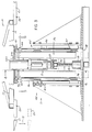
- Fig. 3 is a vertical sectional view illustrating portions of the mechanism for raising and lowering the arms as well as rotating the arms in a horizontal plane.
- Fig. 4 is a vertical cross-sectional view taken substantially along lines 4-4 of Fig.3.
- Fig. 5 is a cross-sectional plan view of the mechanism of Fig. 3 and is taken substantially along lines 5-5 thereof.
- Fig. 6 is a schematic isometric view illustrating the preferred motion of the pallet-supporting arms.
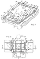
- Fig. 7 is an isometric view of a fork just as it is about to deposit a pallet onto or lift it from a work table.
- Fig. 8 illustrates one known type of clamp which may be utilized on the pallets for attaching unassembled workpieces thereto.
- Fig. 9 is a simplified block diagram for controlling servo motors used to move the turret in its horizontal and vertical planes.
- a carousel 10 is provided with a turret 11 which has bi-directional rotary motion shown by arrow 12 in Fig. 1 and vertical up and down motion as shown by arrow 13 in Fig. 2.
- the work stations are identified as WS1-WS4 in Fig. 1.
- the number of such work stations provided is dependent upon the jobs to be performed. Additionally, while the length of the path of movement 14 corresponds to the angular spacing between work stations WS1 and WS2, the system can be designed to skip work station WS2 and travel from WS1 to WS3, depending on the job being performed, the set-up, the number of workers, etc.
- the turret 11 of Fig. 1 supports a plurality of radially-extending arms 19 at the distal end of each of which is a fork 20 having a pair of spaced apart tines 21, shown more clearly in Fig. 7.
- arms 19 shown, one being located at each of assembly stations AS1-AS3, work stations WS1-WS4 and a delivery station DS.
- the welders may be either arc or spot welders, such, e.g., as shown in U.S. Patents 4,931,617, 4,954,762 and 4,885,560.
- a work table 22 for receipt of pallets 23 thereon. While not shown in detail in Figs. 1 and 2, there is provided, particularly at stations WS1-WS4, a registering mechanism broadly designated 24 in Fig.7. It can thus be seen from what has been described that pallets 23 are indexed in step-by-step fashion from one table to the next and the arms 19 are provided primarily for lifting the pallets from one station and transporting them to the next.
- the arms 19 and the turret 11 on which they are carried do not, therefore, require a great deal of precision either in the extent of angular rotation or raising and lowering of the turret to deposit pallets 23 on the registering mechanism 24 at each work station, and, as will be seen, only two servo motors SM1 and SM2 are provided for the horizontal and vertical movements of the turret 11 and its arms 19.
- welders W1-W4 be properly positioned in relation to tables 22, particularly to the registering mechanism 24 on the tables. It is also necessary that clamps C (Fig. 7) are precisely related to the positions of the registering mechanism 24 so that all of the workpieces which are clamped to the pallets 23 are also located in identical positions for identical fabrication. Although it is not essential to provide registering mechanism such as 24 at assembly stations AS1-AS3 or delivery station DS, it is preferred to do so since all of the pallets will be similar, at least to the extent of the registering mechanism itself. It is feasible that several different fabrication jobs may be performed at the same time by different workers such as 26 and 27 (Fig.
- the registering mechanisms would preferably be the same, particularly where the turret travels only between one work station and the next and returns to the first.
- the parts in bins 28 and 29 can be the same or different, depending upon whether workers 26 and 27 are performing the same or different jobs.
- turret is raised and lowered by servo motor SM1 and rotated on its vertical axis by servo motor SM2.
- Motor SM1 is fixed against rotation by being guided by an upstanding post 30.
- the post 30 is spanned by a cantilevered fork 31 to maintain the motor SM1 stationary relative to turret 11.
- Motor SM1 transmits rotary motion to a screw 32.
- Screw 32 is journaled in a bearing box 33 which is fixed to a base 34 for the carousel 10. Rotation of screw 32 by its motor causes a nut 35 to move up or down within limits permitted by the control switches (not shown) for the motor SM1. As shown in Figs.
- the nut 35 is near the upper end of its travel corresponding essentially to the first horizontal plane 15 in which the arms 19 transport the pallets in a forwarding direction.
- a tubular body structure 36 surrounds the motor SM1 and its screw and nut as shown best in Fig. 5, and provides the primary support for the arms 19 and forks 20.
- a plate 37 is part of the structure 36 and rests on the upper thrust-bearing surface of nut 35. Screw 32 passes freely through an enlarged opening in the plate 37.
- the structure 36 will be driven downwardly by motor SM1 to the dotted-line position shown in Fig. 3.
- the lower end of the tubular body structure 36 can descend through openings 38 in the base 34 and the cantilevered fork 31 will move downwardly along the upstanding post 30 until it approaches plates 39 mounted on base 34.
- Limit switches stop servo motor SM1 before the nut 35 reaches its end positions.
- servo motor SM1 is driven rapidly as it descends until it is almost at the level at which pallets 23 are to be deposited on tables 22.
- the motor then shifts to a low or creep speed to gently set pallets down as the male and female elements of the registering mechanisms engage.
- the turret 11 can be operated at any speed for the remaining descent, returned along the second, lower horizontal plane 17 and then raised along the line 18 to a point just below where the tines 21 of the forks 20 are in position to lift pallets on which work tasks have been completed.
- the speeds along line 16 and plane 17 are sufficient to avoid any delay, and are therefore job dependent.
- Subsequent lifting can be started at a slow speed, and, depending upon the type of registering mechanism 24 used and the height to which pallets 23 must be raised, the final lift can be either slow or rapid.
- Movement of the carousel in horizontal plane 15 is accomplished by the servo motor SM2. That motor is suspended from the body structure 36 as shown in Fig. 4.
- Motor SM2 has a drive pinion 40 meshing with an annular driven ring gear 41.
- a ring gear 41 is the outer race of a bearing 42, with the inner bearing race 43 being fixed to a plate 44 non-rotatably carried by the structure 36. It will thus be seen that operation of servo motor SM2 will rotate the upper structure of the carousel defined by the arms 19 and forks 20 in the horizontal plane 15 relative to the body structure and the non-rotatable inner race 43.
- Servo motor SM2 is also controlled by limit switches (not shown) associated with the ends of travel of the turret 11 or arms 19 and is preferably multi-speed so that it starts smoothly, accelerates and decelerates to a relatively smooth stop.
- Guide means 45 consisting of rods 46 and horizontally spaced sets of upper and lower V-grooved rollers 47 guide the structure 36 vertically during operation of servo motor SM1.
- the inner and outer races of the bearing 42 allow free turret rotation while receiving the weight of the arms 19, forks 20 and pallets 23 containing the workpieces. It can be seen that the vertical and horizontal motions are independent of each other and are provided by independent servo motors.
- servo motor SM2 being mounted on body structure 36, it moves vertically only, but is capable of imparting rotary motion through any angle desired, including up to 360 degrees if that type of operation is chosen.
- the pallet 23 has four guides 48 in spaced sets of two along each of the adjacent perpendicular edges of the pallet 23.
- the guides act as female members of the registering mechanism 24, which also includes a pair of circular rods 49 mounted on the upper surface of the table 22.
- Guides 48 are designed as V-grooved non-rotatable rollers. Their mountings may be provided with eccentric adjustments. Being circular, wear can be compensated for by presenting different points of the roller grooves for contact with the rods 49 when required. It is necessary to have all of the guides 48 in corresponding locations on all of the pallets 23 to the degree of precision required by the jobs to be performed.
- a pair of rollers 50 are fixedly located at the far side of the pallet in Fig.7. Their outer peripheries may rest on a flat bar 51 to stabilize the pallet 23 as it rests on the table 22 if required.
- rods 49 and guides 48 ordinarily provide all of the support needed.
- Fig. 7 also shows tines 21 of one of the forks 20.
- Each tine has a pair of upwardly-facing V-grooves for receiving axles 52 of the guides 48 at those sides of the pallet 23 parallel to the tines 21.
- the V-grooves extend from the inside edge of each tine 21 toward its outside edge to a depth which allows a small amount of space, so that the tines 21 constitute a coarse registering mechanism of the forks 20 to the axles 52 associated with rollers 50 and guides 48 adjacent tines 21. This provides a degree of horizontal "play" of the pallets 22 with respect to tines 21, but, the tines 21 being V-grooved, the axles 52 will settle to the groove bottoms.
- the degree of play allowed by the grooves in tines 21 has to be within the limits to enable the guides 48 on each of the pallets 23 to settle properly on their respective rods 49 at each of the work stations.
- the guides 48 and rods 49 comprise a fine registering mechanism, whereas the axles 52 and the grooves in the tines 21 comprise a coarse registering mechanism.
- Fig. 7 Shown in dotted lines in Fig. 7 are clamps C which press individual workpieces 25 against stops 53. Appropriate aligning marks or elements are provided on the pallets to assure precision location of the workpieces 25 on the pallets. Also depicted in Fig. 7 are a plurality of weld marks 54 which will ultimately be where spot welds are made to fabricate the parts 25 into a unitary structure. Obviously, if the welding to be performed is arc welding, beads will be created along edges such as 55.
- the clamps C may be of any conventional kind. An example of a standard toggle-actuated clamp is shown in Fig. 8, wherein a resilient foot 56 clamps a workpiece 25 downwardly against the upper surface of a pallet 23.
- Fig. 9 illustrates a simplified block diagram of a master control for servo motors SM1 and SM2, and programmed controls PC1-PC4 for welders W1-W4, respectively. Since it is the controlled elements and not the controls that are of significance to this invention, it is believed unnecessary to illustrate and explain the details of the controls for a clear understanding of the invention, since such will be obvious to a person skilled in the control arts.
Landscapes
- Engineering & Computer Science (AREA)
- Mechanical Engineering (AREA)
- Physics & Mathematics (AREA)
- Optics & Photonics (AREA)
- Automatic Assembly (AREA)
Applications Claiming Priority (2)
| Application Number | Priority Date | Filing Date | Title |
|---|---|---|---|
| US07/747,935 US5160079A (en) | 1991-08-21 | 1991-08-21 | Apparatas and method for lifting and transporting palletized workpieces |
| US747935 | 1991-08-21 |
Publications (1)
| Publication Number | Publication Date |
|---|---|
| EP0529465A1 true EP0529465A1 (fr) | 1993-03-03 |
Family
ID=25007308
Family Applications (1)
| Application Number | Title | Priority Date | Filing Date |
|---|---|---|---|
| EP92114022A Withdrawn EP0529465A1 (fr) | 1991-08-21 | 1992-08-18 | Appareil et méthode pour soulever et transporter des palettes supportant des pièces de travail |
Country Status (3)
| Country | Link |
|---|---|
| US (1) | US5160079A (fr) |
| EP (1) | EP0529465A1 (fr) |
| JP (1) | JPH05237695A (fr) |
Cited By (3)
| Publication number | Priority date | Publication date | Assignee | Title |
|---|---|---|---|---|
| FR2712221A1 (fr) * | 1993-11-10 | 1995-05-19 | Comau Spa | Dispositif et procédé pour changer de position deux tables de travail, en particulier deux tables porte-pièces destinées à l'assemblage de groupes comprenant des éléments en tôle emboutie. |
| EP1060831A1 (fr) * | 1999-06-18 | 2000-12-20 | Société pour Faciliter les Operations Mecaniques (S.F.O.M.) S.R.L. | Dispositif de transfert de pièces à usiner |
| DE19950077A1 (de) * | 1999-10-18 | 2001-04-26 | Thyssenkrupp Ind Ag | Verfahren und Vorrichtung zum Bearbeiten von Bauteilen |
Families Citing this family (13)
| Publication number | Priority date | Publication date | Assignee | Title |
|---|---|---|---|---|
| PT976491E (pt) * | 1998-06-01 | 2001-06-29 | Comau Spa | Dispositivo para a montagem de carrocarias de veiculos motorizados ou de sub-conjuntos das mesmas que possui um sistema integrado de deteccao das deformacoes e processo para a montagem que utiliza este dispositivo |
| US6371362B1 (en) | 1999-12-23 | 2002-04-16 | Abb T&D Technology Ltd. | Robotic welding of brackets inside metal enclosures |
| JP4763254B2 (ja) * | 2004-06-16 | 2011-08-31 | コマツ産機株式会社 | 熱切断機 |
| DE102012112009B4 (de) * | 2012-12-10 | 2025-09-11 | Dr. Ing. H.C. F. Porsche Aktiengesellschaft | Bearbeitungsstation für Karosserie-Bauteile |
| KR101450478B1 (ko) * | 2013-11-25 | 2014-10-13 | 주식회사 윌리언스 | 필름전사 시스템 |
| CN104858592A (zh) * | 2015-05-25 | 2015-08-26 | 安徽好运机械有限公司 | 一种叉车货叉架体的柔性化搭焊模具 |
| US20180111214A1 (en) * | 2016-10-26 | 2018-04-26 | Metalsa S.A. De C.V. | Flexible assembly line and method |
| CN107804661B (zh) * | 2017-11-23 | 2023-08-22 | 苏州富强科技有限公司 | 一种四工位转台 |
| CN109676306B (zh) * | 2018-12-25 | 2020-12-29 | 江苏鲁安特智能装备科技有限公司 | 叉车连接件组合焊装置 |
| CN112719561B (zh) * | 2019-10-14 | 2024-11-19 | 天津环博科技有限责任公司 | 一种焊接设备的全自动上料下料设备 |
| KR102390335B1 (ko) * | 2020-12-23 | 2022-04-25 | 주식회사 신영 | 유연 생산플랫폼용 이동형 보조 용접장치 |
| CN112958931B (zh) * | 2021-02-24 | 2022-08-19 | 海城三鱼泵业有限公司 | 一种转盘式水泵焊接装置 |
| CN116275506A (zh) * | 2023-04-28 | 2023-06-23 | 武汉楚天工业激光设备有限公司 | 一种激光焊接多工位焊接台及其使用方法 |
Citations (4)
| Publication number | Priority date | Publication date | Assignee | Title |
|---|---|---|---|---|
| WO1987003236A1 (fr) * | 1985-11-30 | 1987-06-04 | Expert Maschinenbau Gmbh | Dispositif de table rotative a mouvement vertical |
| EP0224931A2 (fr) * | 1985-12-06 | 1987-06-10 | Toyoda Koki Kabushiki Kaisha | Dispositif de changement de palette pour machine-outil |
| US4673076A (en) * | 1984-09-04 | 1987-06-16 | Kearney & Trecker Corporation | Rotary shuttle for machine tools |
| EP0409085A1 (fr) * | 1989-07-17 | 1991-01-23 | MAHO Aktiengesellschaft | Echangeur de palettes pour machines-outils |
Family Cites Families (6)
| Publication number | Priority date | Publication date | Assignee | Title |
|---|---|---|---|---|
| US3570834A (en) * | 1968-08-09 | 1971-03-16 | Hoglund Eng & Mfg Co Inc | Work fixture and fixture shuttle for moving a plurality of workpieces to and from working positions |
| US4049500A (en) * | 1974-05-10 | 1977-09-20 | Kamm Lawrence J | Manufacturing machine |
| US4390172A (en) * | 1980-11-28 | 1983-06-28 | Presco, Inc. | Precise quick-release positioning mechanism |
| JPS57194847A (en) * | 1981-05-24 | 1982-11-30 | Murata Mach Ltd | Automatic tool exchanging system |
| US4611749A (en) * | 1983-11-28 | 1986-09-16 | Mazda Motor Corporation | Method of and system for assembling a plurality of parts into a unit |
| US5044541A (en) * | 1989-04-21 | 1991-09-03 | Nissan Motor Co., Ltd. | Method and apparatus for assembling vehicle body |
-
1991
- 1991-08-21 US US07/747,935 patent/US5160079A/en not_active Expired - Fee Related
-
1992
- 1992-08-18 EP EP92114022A patent/EP0529465A1/fr not_active Withdrawn
- 1992-08-21 JP JP4222760A patent/JPH05237695A/ja active Pending
Patent Citations (5)
| Publication number | Priority date | Publication date | Assignee | Title |
|---|---|---|---|---|
| US4673076A (en) * | 1984-09-04 | 1987-06-16 | Kearney & Trecker Corporation | Rotary shuttle for machine tools |
| US4673076B1 (en) * | 1984-09-04 | 2000-02-01 | Kearney & Trecker Corp | Rotary shuttle for machine tools |
| WO1987003236A1 (fr) * | 1985-11-30 | 1987-06-04 | Expert Maschinenbau Gmbh | Dispositif de table rotative a mouvement vertical |
| EP0224931A2 (fr) * | 1985-12-06 | 1987-06-10 | Toyoda Koki Kabushiki Kaisha | Dispositif de changement de palette pour machine-outil |
| EP0409085A1 (fr) * | 1989-07-17 | 1991-01-23 | MAHO Aktiengesellschaft | Echangeur de palettes pour machines-outils |
Non-Patent Citations (1)
| Title |
|---|
| IBM TECHNICAL DISCLOSURE BULLETIN vol. 17, no. 10, March 1975, NEW YORK US pages 2859 - 2862 A. MACK 'Work carrier gripper transfert mechanism' * |
Cited By (4)
| Publication number | Priority date | Publication date | Assignee | Title |
|---|---|---|---|---|
| FR2712221A1 (fr) * | 1993-11-10 | 1995-05-19 | Comau Spa | Dispositif et procédé pour changer de position deux tables de travail, en particulier deux tables porte-pièces destinées à l'assemblage de groupes comprenant des éléments en tôle emboutie. |
| EP1060831A1 (fr) * | 1999-06-18 | 2000-12-20 | Société pour Faciliter les Operations Mecaniques (S.F.O.M.) S.R.L. | Dispositif de transfert de pièces à usiner |
| FR2795012A1 (fr) * | 1999-06-18 | 2000-12-22 | Faciliter Les Operations Mecan | Dispositif de transfert de pieces a usiner |
| DE19950077A1 (de) * | 1999-10-18 | 2001-04-26 | Thyssenkrupp Ind Ag | Verfahren und Vorrichtung zum Bearbeiten von Bauteilen |
Also Published As
| Publication number | Publication date |
|---|---|
| JPH05237695A (ja) | 1993-09-17 |
| US5160079A (en) | 1992-11-03 |
Similar Documents
| Publication | Publication Date | Title |
|---|---|---|
| US5160079A (en) | Apparatas and method for lifting and transporting palletized workpieces | |
| EP0069476B1 (fr) | Dispositif pour le transport de pièces de travail | |
| EP2164678B1 (fr) | Systeme de chargement/dechargement pour centre de decoupe de feuilles et procede de manutention associes | |
| CN113523820B (zh) | 一种智能制造流水线的加工方法 | |
| CN112041112A (zh) | 汽车白车身组件的组焊或拼接生产线 | |
| CN216582385U (zh) | 一种链式环型储料装置 | |
| EP0310998B1 (fr) | Palettiseur avec mâchoires pour l'industrie graphique | |
| JPS6260218B2 (fr) | ||
| CN215658949U (zh) | 一种智能制造流水线 | |
| CN113941667B (zh) | 一种挡圈自动化生产线 | |
| EP0408184A1 (fr) | Système de transport automatique | |
| CN109848285B (zh) | 用于高速冲槽机自动上下料的四轴平面式机器人集成系统 | |
| CN114918585B (zh) | 一种搬运车货叉工装焊接系统 | |
| CN216917486U (zh) | 齿轮轴上下料输送线及配套的渗碳打标自动化生产线 | |
| CN212291934U (zh) | 一种自动智能加工系统 | |
| JPS63109931A (ja) | 立形マシニングセンタ | |
| JPH0780676A (ja) | レーザ加工装置 | |
| US5337938A (en) | Workpiece handling system | |
| CN215093555U (zh) | 一种机械手的自动定位机构 | |
| KR101600311B1 (ko) | 연속식 부품 공급장치 | |
| CN116443496A (zh) | 一种链式环型储料装置及操作方法 | |
| CN113500446B (zh) | 一种用于曲轴存放位置自动转移的数控机床 | |
| JPH01321212A (ja) | 被搬送物の移載装置 | |
| CN219275226U (zh) | 一种工件顶升机构 | |
| JPH07124851A (ja) | 自動加工システム |
Legal Events
| Date | Code | Title | Description |
|---|---|---|---|
| PUAI | Public reference made under article 153(3) epc to a published international application that has entered the european phase |
Free format text: ORIGINAL CODE: 0009012 |
|
| AK | Designated contracting states |
Kind code of ref document: A1 Designated state(s): DE FR GB IT |
|
| 18D | Application deemed to be withdrawn |
Effective date: 19930904 |