EP0529497A1 - Dispositif d'arrosage - Google Patents
Dispositif d'arrosage Download PDFInfo
- Publication number
- EP0529497A1 EP0529497A1 EP92114132A EP92114132A EP0529497A1 EP 0529497 A1 EP0529497 A1 EP 0529497A1 EP 92114132 A EP92114132 A EP 92114132A EP 92114132 A EP92114132 A EP 92114132A EP 0529497 A1 EP0529497 A1 EP 0529497A1
- Authority
- EP
- European Patent Office
- Prior art keywords
- water path
- path
- water
- defining member
- recess
- Prior art date
- Legal status (The legal status is an assumption and is not a legal conclusion. Google has not performed a legal analysis and makes no representation as to the accuracy of the status listed.)
- Granted
Links
Images



Classifications
-
- A—HUMAN NECESSITIES
- A01—AGRICULTURE; FORESTRY; ANIMAL HUSBANDRY; HUNTING; TRAPPING; FISHING
- A01G—HORTICULTURE; CULTIVATION OF VEGETABLES, FLOWERS, RICE, FRUIT, VINES, HOPS OR SEAWEED; FORESTRY; WATERING
- A01G25/00—Watering gardens, fields, sports grounds or the like
- A01G25/02—Watering arrangements located above the soil which make use of perforated pipe-lines or pipe-lines with dispensing fittings, e.g. for drip irrigation
- A01G25/023—Dispensing fittings for drip irrigation, e.g. drippers
Definitions
- the present invention relates to agricultural irrigation devices generally and more specifically to relatively low volume water sprayers and drip irrigators.
- U.S. Patent 4,466,462 describes a circuitous path flow restrictor including a fluid director member having a core and a plurality of finds extending from the core and defining alternately axially offset notches.
- the fluid director member is encircled by a containment member such that a serpentine fluid flow path is defined therebetween to provide a fluid flow resistance level equivalent to a simple orifice of much smaller diameter.
- the fluid director member can be made by a precision casting process for economy of manufacture.
- the present invention seeks to provide an improved, compact irrigation device which is injection moldable from a small number of parts and which is relatively resistant to clogging due to particulate matter in the water.
- an irrigation device including a first interior water path defining member and a second exterior water path defining member, cooperating with the first water path defining member to define a circuitous water path including sequential water path components extending generally in three mutually perpendicular directions.
- an irrigation device including a first interior water path defining member and a second exterior water path defining member, cooperating with the first water path defining member to define a circuitous water path, the irrigation device including a water inlet and a water outlet arranged about an axis and the circuitous water path including a plurality of different circumferential path portions arranged at a plurality of different radii with respect to the axis.
- the water path also includes a plurality of radially extending path portions and a plurality of axially extending path portions.
- each circumferential path portion is separated from a succeeding circumferential path portion by at least one radially extending path portion and at least one axially extending path portion.
- the irrigation device comprises only two pieces, which are readily injection molded of plastic and press-fit together.
- the irrigation device may be a sprinkler or alternatively a dripper.
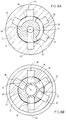
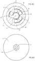
- FIGS. 1 - 4 and 6A - 6D illustrate a sprinkler constructed and operative in accordance with a preferred embodiment of the present invention and comprising an interior flow path defining element 10 and an exterior flow path defining element 12, cooperating therewith.
- Element 10 defines a water inlet 14, typically of the piercing type, which can be simply inserted in an appropriately sized hole in a water conduit, such as a plastic water pipe.
- Element 12 defines a water outlet aperture 16, which, in the illustrated, preferred embodiment of the invention is axially aligned with inlet 14, along an axis 18 defined by arrow labeled 18, which also defines the water inlet direction.
- press fit engagement between the interior element 10 and the exterior element 12 defines a multi-level, multi-directional, multi-radius tortuous flow reducing pathway, which is illustrated generally by arrowed line 20.
- Fig. 6A water from inlet 14 passes along a passageway 22 in interior element 10 and communications with a recess 24 in exterior element 12.
- Recess 24 defines an axial flow path portion which extends parallel to axis 18, and which communicates with a recess 26 formed in interior element 10 (Fig. 6B), thus defining a radially extending flow path portion which extends radially inward with respect to axis 18.
- Recess 26 communicates with a circumferentially extending recess 28 formed in element 12 (Fig. 6C), which defines a circumferentially extending flow path portion extending at a first radius about axis 18 and communicating with a corresponding recess 30, azimuthally separated from recess 26 and also formed in element 10.
- the water path from recess 28 to recess 30 thus defines an axial flow path portion, as seen clearly in Fig. 1, wherein the water moves in a direction opposite that indicated by arrow 18. From recess 30, the water moves along a radially outwardly extending flow path portion into a recess 32 formed in element 12 (Fig. 6B0.
- Recess 32 defines an axially extending flow path portion which extends parallel to axis 18 but in a direction opposite to that of arrow 18. Recess 32 communicates with a circumferentially extending recess 34 formed in element 10 (Fig. 6A), which defines a circumferentially extending flow path portion extending at a second radius, smaller than the first radius, about axis 18 and communicating with a corresponding recess 36, azimuthally separated from recess 34 and also formed in element 12.
- Recess 36 defines an axial flow path portion which extends parallel to axis 18, and which communicates with a recess 38 formed in interior element 10 (Fig. 6B), thus defining a radially extending flow path portion which extends radially inward with respect to axis 18.
- Recess 38 communicates with a circumferentially extending recess 40 formed in element 10 (Fig. 6C), which defines a circumferentially extending flow path portion extending at the first radius about axis 18 and communicating with a corresponding recess 42, azimuthally separated from recess 38 and also formed in element 10.
- the water path from recess 40 to recess 42 thus defines an axial flow path portion, as seen clearly in Fig. 1, wherein the water moves in a direction opposite that indicated by arrow 18. From recess 42, the water moves along a radially outwardly extending flow path portion into a recess 44 formed in element 12.
- Recess 44 defines an axially extending flow path portion which extends parallel to axis 18 but in a direction opposite to that of arrow 18. Recess 44 communicates with a circumferentially extending recess 46 formed in element 10 (Fig. 6A), which defines a circumferentially extending flow path portion extending at the second radius, about axis 18 and communicating with a corresponding recess 48, azimuthally separated from recess 44 and also formed in element 12.
- Recess 48 defines an axial flow path portion which extends parallel to axis 18, and which communicates with a recess 50 formed in interior element 10 (Fig. 6B), thus defining a radially extending flow path portion which extends radially inward with respect to axis 18.
- Recess 50 communicates via a passageway 52 (Fig. 6C with the outlet 16.
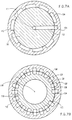
- Figs. 5 and 7A - 7D illustrate a dripper constructed and operative in accordance with a preferred embodiment of the present invention and comprising an interior flow path defining element 110 and an exterior flow path defining element 112, cooperating therewith.
- Element 110 defines a water inlet 114, typically of the piercing type, which can be simply inserted in an appropriately sized hole in a water conduit, such as a plastic water pipe.
- Element 112 defines a water outlet aperture 116, which, in the illustrated, preferred embodiment of the invention is axially aligned with inlet 114, along an axis 118 defined by arrow labeled 118, which also defines the water inlet direction.
- press fit engagement between the interior element 110 and the exterior element 112 defines a multi-level, multi-directional, multi-radius tortuous flow reducing pathway, which is similar to that illustrated in Figs. 1 and 2 but employs a greater number of direction changes and thus a longer flow path, thereby to provide greater flow rate reduction than the embodiment of Figs. 1 and 2.
- water from inlet 114 passes along a passageway 122 in interior element 110 and communications with a recess 124 in exterior element 112.
- Recess 124 defines an axial flow path portion which extends parallel to axis 118, and which communicates with a recess 126 formed in interior element 110 (Fig. 7B), thus defining a radially extending flow path portion which extends radially inward with respect to axis 118.
- Recess 126 communicates with a circumferentially and radially extending curved recess 128 formed in element 112 (Fig. 7C) , which defines a corresponding flow path portion communicating with a corresponding recess 130, azimuthally separated from recess 126 and also formed in element 110.
- the water path from recess 128 to recess 130 thus defines an axial flow path portion wherein the water moves in a direction opposite that indicated by arrow 118. From recess 130, the water moves along a radially outwardly extending flow path portion into a recess 132 formed in element 112.
- Recess 132 defines an axially extending flow path portion which extends parallel to axis 118 but in a direction opposite to that of arrow 118. Recess 132 communicates with a circumferentially extending recess 134 formed in element 112 (Fig. 7A), which defines a circumferentially extending flow path portion extending at a second radius, larger than the radius at which recess 128 is located.
- Recess 134 communicates with a recess 136, azimuthally separated from recess 130 and also formed in element 112.
- Recess 136 defines an axial flow path portion which extends parallel to axis 118, and which communicates with a recess 138 formed in interior element 110 (Fig. 7B), thus defining a radially extending flow path portion which extends radially inward with respect to axis 118.
- Recess 138 communicates with a circumferentially and radially extending curved recess 140 formed in element 112 (Fig. 7C), which may be identical to recess 128 in structure and function. Additional recesses identical to recesses 128 and 140 as well as recesses 130, 132, 134, 136 and 138 may be provided and interconnected in the same or similar manner as described hereinabove to define a flow and pressure reducing pathway of suitable flow and pressure reduction characteristics that terminates at a recess 150 which communicates with a passageway 152, which in turn leads to liquid outlet 116.
Landscapes
- Life Sciences & Earth Sciences (AREA)
- Soil Sciences (AREA)
- Engineering & Computer Science (AREA)
- Water Supply & Treatment (AREA)
- Environmental Sciences (AREA)
- Nozzles (AREA)
- Massaging Devices (AREA)
- Fluid-Driven Valves (AREA)
- Endoscopes (AREA)
Applications Claiming Priority (2)
| Application Number | Priority Date | Filing Date | Title |
|---|---|---|---|
| IL99281A IL99281A (en) | 1991-08-22 | 1991-08-22 | Irrigation device |
| IL99281 | 1991-08-22 |
Publications (2)
| Publication Number | Publication Date |
|---|---|
| EP0529497A1 true EP0529497A1 (fr) | 1993-03-03 |
| EP0529497B1 EP0529497B1 (fr) | 1996-01-10 |
Family
ID=11062828
Family Applications (1)
| Application Number | Title | Priority Date | Filing Date |
|---|---|---|---|
| EP92114132A Expired - Lifetime EP0529497B1 (fr) | 1991-08-22 | 1992-08-19 | Dispositif d'arrosage |
Country Status (8)
| Country | Link |
|---|---|
| US (1) | US5316220A (fr) |
| EP (1) | EP0529497B1 (fr) |
| AT (1) | ATE132692T1 (fr) |
| AU (1) | AU665203B2 (fr) |
| DE (1) | DE69207514T2 (fr) |
| ES (1) | ES2082304T3 (fr) |
| GR (1) | GR3018649T3 (fr) |
| IL (1) | IL99281A (fr) |
Cited By (2)
| Publication number | Priority date | Publication date | Assignee | Title |
|---|---|---|---|---|
| GR1002825B (el) * | 1996-12-12 | 1997-12-19 | ��������� - Palaplast A.B.E.E. | Πλευρικος σταλακτης αρδευσης σταθερης παροχης με θαλαμο ηρεμιας. |
| WO2007116389A1 (fr) * | 2006-04-09 | 2007-10-18 | Netafim Ltd. | Goutteurs et raccords de tuyaux |
Families Citing this family (25)
| Publication number | Priority date | Publication date | Assignee | Title |
|---|---|---|---|---|
| US6238081B1 (en) | 1999-03-23 | 2001-05-29 | Hydro Systems Company | Ultra-lean dilution apparatus |
| AU151557S (en) | 2002-08-15 | 2003-04-29 | Gardena Kress Kastner G M B H | Sprinkler |
| US7648085B2 (en) | 2006-02-22 | 2010-01-19 | Rain Bird Corporation | Drip emitter |
| US20080191059A1 (en) * | 2007-02-13 | 2008-08-14 | Walker Samuel C | Spray nozzle with inverted water flow |
| US8439282B2 (en) * | 2009-02-06 | 2013-05-14 | Rain Bird Corporation | Low flow irrigation emitter |
| USD615151S1 (en) * | 2009-02-06 | 2010-05-04 | Rain Bird Corporation | Low flow irrigation emitter |
| US9485923B2 (en) | 2012-03-26 | 2016-11-08 | Rain Bird Corporation | Elastomeric emitter and methods relating to same |
| US9877440B2 (en) | 2012-03-26 | 2018-01-30 | Rain Bird Corporation | Elastomeric emitter and methods relating to same |
| US20130248622A1 (en) | 2012-03-26 | 2013-09-26 | Jae Yung Kim | Drip line and emitter and methods relating to same |
| US10440903B2 (en) | 2012-03-26 | 2019-10-15 | Rain Bird Corporation | Drip line emitter and methods relating to same |
| US9872444B2 (en) | 2013-03-15 | 2018-01-23 | Rain Bird Corporation | Drip emitter |
| US9258949B2 (en) | 2013-06-19 | 2016-02-16 | National Diversified Sales, Inc. | Adjustable drip emitter |
| US10631473B2 (en) | 2013-08-12 | 2020-04-28 | Rain Bird Corporation | Elastomeric emitter and methods relating to same |
| US10285342B2 (en) | 2013-08-12 | 2019-05-14 | Rain Bird Corporation | Elastomeric emitter and methods relating to same |
| USD811179S1 (en) | 2013-08-12 | 2018-02-27 | Rain Bird Corporation | Emitter part |
| US9883640B2 (en) | 2013-10-22 | 2018-02-06 | Rain Bird Corporation | Methods and apparatus for transporting elastomeric emitters and/or manufacturing drip lines |
| US10330559B2 (en) | 2014-09-11 | 2019-06-25 | Rain Bird Corporation | Methods and apparatus for checking emitter bonds in an irrigation drip line |
| CN105170353A (zh) * | 2015-06-30 | 2015-12-23 | 开平市亿洋塑胶制品有限公司 | 一种pvc高压喷雾管 |
| US10375904B2 (en) | 2016-07-18 | 2019-08-13 | Rain Bird Corporation | Emitter locating system and related methods |
| US11051466B2 (en) | 2017-01-27 | 2021-07-06 | Rain Bird Corporation | Pressure compensation members, emitters, drip line and methods relating to same |
| US10626998B2 (en) | 2017-05-15 | 2020-04-21 | Rain Bird Corporation | Drip emitter with check valve |
| KR101962256B1 (ko) | 2017-08-28 | 2019-03-26 | 주식회사 남경 | 드립 이미터 |
| USD883048S1 (en) | 2017-12-12 | 2020-05-05 | Rain Bird Corporation | Emitter part |
| US11985924B2 (en) | 2018-06-11 | 2024-05-21 | Rain Bird Corporation | Emitter outlet, emitter, drip line and methods relating to same |
| US12207599B2 (en) | 2021-10-12 | 2025-01-28 | Rain Bird Corporation | Emitter coupler and irrigation system |
Citations (3)
| Publication number | Priority date | Publication date | Assignee | Title |
|---|---|---|---|---|
| FR2387690A1 (fr) * | 1977-04-22 | 1978-11-17 | Lego Lemelstrich Ltd | Dispositif d'ecoulement goutte a goutte |
| US4166576A (en) * | 1977-10-17 | 1979-09-04 | Safe-T-Lawn, Inc. | Lock valve for sprinkler |
| EP0327232A2 (fr) * | 1988-02-01 | 1989-08-09 | James Hardie Irrigation, Inc | Dispositif pour délivrer des gouttes |
Family Cites Families (7)
| Publication number | Priority date | Publication date | Assignee | Title |
|---|---|---|---|---|
| US3791587A (en) * | 1972-03-17 | 1974-02-12 | M Drori | Flow-reducing device particularly useful for trickle irrigation |
| IL45327A (en) * | 1974-07-22 | 1980-07-31 | Baruch Yaron | Pressure reducing device for fluids particularly for irrigation pipes |
| US4022384A (en) * | 1975-12-08 | 1977-05-10 | Hancor, Inc. | Irrigation tubing |
| IL55533A0 (en) * | 1978-09-07 | 1978-12-17 | Lego Lemelstrich Ltd | Improved drip emitter |
| WO1983002647A1 (fr) * | 1982-02-01 | 1983-08-04 | Morris, Hugh, C. | Reducteur du debit dans un chemin de circuit et procede |
| JPH07120351B2 (ja) * | 1986-03-14 | 1995-12-20 | 株式会社日立製作所 | シミュレーションプログラム生成方法 |
| US5031837A (en) * | 1990-01-02 | 1991-07-16 | Raindrip, Inc. | Drip irrigator |
-
1991
- 1991-08-22 IL IL99281A patent/IL99281A/en not_active IP Right Cessation
-
1992
- 1992-08-18 US US07/931,917 patent/US5316220A/en not_active Expired - Fee Related
- 1992-08-19 AT AT92114132T patent/ATE132692T1/de not_active IP Right Cessation
- 1992-08-19 ES ES92114132T patent/ES2082304T3/es not_active Expired - Lifetime
- 1992-08-19 DE DE69207514T patent/DE69207514T2/de not_active Expired - Fee Related
- 1992-08-19 EP EP92114132A patent/EP0529497B1/fr not_active Expired - Lifetime
- 1992-08-21 AU AU21227/92A patent/AU665203B2/en not_active Ceased
-
1996
- 1996-01-11 GR GR950403729T patent/GR3018649T3/el unknown
Patent Citations (3)
| Publication number | Priority date | Publication date | Assignee | Title |
|---|---|---|---|---|
| FR2387690A1 (fr) * | 1977-04-22 | 1978-11-17 | Lego Lemelstrich Ltd | Dispositif d'ecoulement goutte a goutte |
| US4166576A (en) * | 1977-10-17 | 1979-09-04 | Safe-T-Lawn, Inc. | Lock valve for sprinkler |
| EP0327232A2 (fr) * | 1988-02-01 | 1989-08-09 | James Hardie Irrigation, Inc | Dispositif pour délivrer des gouttes |
Cited By (3)
| Publication number | Priority date | Publication date | Assignee | Title |
|---|---|---|---|---|
| GR1002825B (el) * | 1996-12-12 | 1997-12-19 | ��������� - Palaplast A.B.E.E. | Πλευρικος σταλακτης αρδευσης σταθερης παροχης με θαλαμο ηρεμιας. |
| WO2007116389A1 (fr) * | 2006-04-09 | 2007-10-18 | Netafim Ltd. | Goutteurs et raccords de tuyaux |
| US8091800B2 (en) | 2006-04-09 | 2012-01-10 | Netafim, Ltd. | Drippers and pipe couplers |
Also Published As
| Publication number | Publication date |
|---|---|
| DE69207514T2 (de) | 1996-05-30 |
| EP0529497B1 (fr) | 1996-01-10 |
| IL99281A0 (en) | 1992-07-15 |
| AU665203B2 (en) | 1995-12-21 |
| IL99281A (en) | 1998-04-05 |
| GR3018649T3 (en) | 1996-04-30 |
| ATE132692T1 (de) | 1996-01-15 |
| US5316220A (en) | 1994-05-31 |
| DE69207514D1 (de) | 1996-02-22 |
| ES2082304T3 (es) | 1996-03-16 |
| AU2122792A (en) | 1993-02-25 |
Similar Documents
| Publication | Publication Date | Title |
|---|---|---|
| EP0529497A1 (fr) | Dispositif d'arrosage | |
| US3791587A (en) | Flow-reducing device particularly useful for trickle irrigation | |
| US4511258A (en) | Static material mixing apparatus | |
| DE60202251T2 (de) | Gerät zur Regelung des Durchflusses medizinischer Flüssigkeiten zu einem Patienten | |
| US5045068A (en) | Flow rate regulator for liquid medicine or blood transfusion unit | |
| US20030042335A1 (en) | Fluid distribution emitter and system | |
| EP0327232A2 (fr) | Dispositif pour délivrer des gouttes | |
| EP1741458B9 (fr) | Dispositif de traitement de sang dans un circuit sanguin extracorporel | |
| CA2457197A1 (fr) | Dispositif de reduction de la pression de fluide | |
| JPH05276842A (ja) | 調整滴下潅漑放出器 | |
| WO1998010635A1 (fr) | Element de regularisation de debit et unites d'irrigation au goutte-a-goutte dans lequel il est utilise | |
| AU2002339896A1 (en) | Fluid distribution emitter and system | |
| US4043360A (en) | Pressure reducing device for fluids | |
| US20080017260A1 (en) | Multirate tubing flow restrictor | |
| KR890000138A (ko) | 병렬여과 회로 | |
| DE60109859T2 (de) | Pumpeinheit für ein Fluid, insbesondere Blut | |
| EP1668249B1 (fr) | Pompe peristaltique | |
| EP4706932A2 (fr) | Ensemble raccord de conduites à écoulement optimisé | |
| DE202010000078U1 (de) | Fluiddurchströmte Verbindungssysteme zum Einsatz in der Medizin und Medizintechnik | |
| EP0150998A2 (fr) | Indicateur de passage du liquide pour outillage agricole | |
| WO2004037378A1 (fr) | Panier de protection pour crepine et procede de fabrication et d'utilisation correspondant | |
| DE19742230C2 (de) | Akkumulator für eine nach dem "Orifice"-Prinzip arbeitende Klimaanlage, insbesondere Fahrzeugklimaanlage | |
| EP1746479A1 (fr) | Pompe méchanique pour des liquides | |
| WO2001069203A3 (fr) | Procede d'etablissement d'au moins un ecoulement enveloppe dans un canal | |
| EP1549362A1 (fr) | Resistance de flux d'aspiration |
Legal Events
| Date | Code | Title | Description |
|---|---|---|---|
| PUAI | Public reference made under article 153(3) epc to a published international application that has entered the european phase |
Free format text: ORIGINAL CODE: 0009012 |
|
| AK | Designated contracting states |
Kind code of ref document: A1 Designated state(s): AT BE CH DE DK ES FR GB GR IE IT LI LU NL PT SE |
|
| 17P | Request for examination filed |
Effective date: 19930903 |
|
| 17Q | First examination report despatched |
Effective date: 19931008 |
|
| GRAA | (expected) grant |
Free format text: ORIGINAL CODE: 0009210 |
|
| AK | Designated contracting states |
Kind code of ref document: B1 Designated state(s): AT BE CH DE DK ES FR GB GR IE IT LI LU NL PT SE |
|
| PG25 | Lapsed in a contracting state [announced via postgrant information from national office to epo] |
Ref country code: LI Effective date: 19960110 Ref country code: DK Effective date: 19960110 Ref country code: CH Effective date: 19960110 Ref country code: BE Effective date: 19960110 Ref country code: AT Effective date: 19960110 |
|
| REF | Corresponds to: |
Ref document number: 132692 Country of ref document: AT Date of ref document: 19960115 Kind code of ref document: T |
|
| ITF | It: translation for a ep patent filed | ||
| REG | Reference to a national code |
Ref country code: IE Ref legal event code: FG4D Free format text: 66842 |
|
| REF | Corresponds to: |
Ref document number: 69207514 Country of ref document: DE Date of ref document: 19960222 |
|
| REG | Reference to a national code |
Ref country code: ES Ref legal event code: FG2A Ref document number: 2082304 Country of ref document: ES Kind code of ref document: T3 |
|
| ET | Fr: translation filed | ||
| REG | Reference to a national code |
Ref country code: GR Ref legal event code: FG4A Free format text: 3018649 |
|
| PG25 | Lapsed in a contracting state [announced via postgrant information from national office to epo] |
Ref country code: SE Effective date: 19960410 |
|
| SC4A | Pt: translation is available |
Free format text: 960110 AVAILABILITY OF NATIONAL TRANSLATION |
|
| REG | Reference to a national code |
Ref country code: CH Ref legal event code: PL |
|
| PG25 | Lapsed in a contracting state [announced via postgrant information from national office to epo] |
Ref country code: IE Free format text: LAPSE BECAUSE OF NON-PAYMENT OF DUE FEES Effective date: 19960819 Ref country code: GB Effective date: 19960819 |
|
| PG25 | Lapsed in a contracting state [announced via postgrant information from national office to epo] |
Ref country code: LU Free format text: LAPSE BECAUSE OF NON-PAYMENT OF DUE FEES Effective date: 19960831 |
|
| PLBE | No opposition filed within time limit |
Free format text: ORIGINAL CODE: 0009261 |
|
| 26N | No opposition filed | ||
| GBPC | Gb: european patent ceased through non-payment of renewal fee |
Effective date: 19960819 |
|
| PGFP | Annual fee paid to national office [announced via postgrant information from national office to epo] |
Ref country code: NL Payment date: 19980811 Year of fee payment: 7 |
|
| PGFP | Annual fee paid to national office [announced via postgrant information from national office to epo] |
Ref country code: PT Payment date: 19980813 Year of fee payment: 7 |
|
| PGFP | Annual fee paid to national office [announced via postgrant information from national office to epo] |
Ref country code: DE Payment date: 19980819 Year of fee payment: 7 |
|
| PGFP | Annual fee paid to national office [announced via postgrant information from national office to epo] |
Ref country code: ES Payment date: 19980824 Year of fee payment: 7 |
|
| PGFP | Annual fee paid to national office [announced via postgrant information from national office to epo] |
Ref country code: FR Payment date: 19980828 Year of fee payment: 7 |
|
| PGFP | Annual fee paid to national office [announced via postgrant information from national office to epo] |
Ref country code: GR Payment date: 19980831 Year of fee payment: 7 |
|
| PG25 | Lapsed in a contracting state [announced via postgrant information from national office to epo] |
Ref country code: ES Free format text: LAPSE BECAUSE OF NON-PAYMENT OF DUE FEES Effective date: 19990820 |
|
| PG25 | Lapsed in a contracting state [announced via postgrant information from national office to epo] |
Ref country code: GR Free format text: LAPSE BECAUSE OF NON-PAYMENT OF DUE FEES Effective date: 19990831 |
|
| PG25 | Lapsed in a contracting state [announced via postgrant information from national office to epo] |
Ref country code: PT Free format text: LAPSE BECAUSE OF NON-PAYMENT OF DUE FEES Effective date: 20000229 |
|
| PG25 | Lapsed in a contracting state [announced via postgrant information from national office to epo] |
Ref country code: NL Free format text: LAPSE BECAUSE OF NON-PAYMENT OF DUE FEES Effective date: 20000301 |
|
| PG25 | Lapsed in a contracting state [announced via postgrant information from national office to epo] |
Ref country code: FR Free format text: LAPSE BECAUSE OF NON-PAYMENT OF DUE FEES Effective date: 20000428 |
|
| NLV4 | Nl: lapsed or anulled due to non-payment of the annual fee |
Effective date: 20000301 |
|
| PG25 | Lapsed in a contracting state [announced via postgrant information from national office to epo] |
Ref country code: DE Free format text: LAPSE BECAUSE OF NON-PAYMENT OF DUE FEES Effective date: 20000601 |
|
| REG | Reference to a national code |
Ref country code: PT Ref legal event code: MM4A Free format text: LAPSE DUE TO NON-PAYMENT OF FEES Effective date: 20000229 |
|
| REG | Reference to a national code |
Ref country code: FR Ref legal event code: ST |
|
| REG | Reference to a national code |
Ref country code: ES Ref legal event code: FD2A Effective date: 20000911 |
|
| PG25 | Lapsed in a contracting state [announced via postgrant information from national office to epo] |
Ref country code: IT Free format text: LAPSE BECAUSE OF NON-PAYMENT OF DUE FEES;WARNING: LAPSES OF ITALIAN PATENTS WITH EFFECTIVE DATE BEFORE 2007 MAY HAVE OCCURRED AT ANY TIME BEFORE 2007. THE CORRECT EFFECTIVE DATE MAY BE DIFFERENT FROM THE ONE RECORDED. Effective date: 20050819 |