EP0529516A1 - Verfahren zur Herstellung eines magnetischen Aufzeichnungsmediums - Google Patents
Verfahren zur Herstellung eines magnetischen Aufzeichnungsmediums Download PDFInfo
- Publication number
- EP0529516A1 EP0529516A1 EP92114235A EP92114235A EP0529516A1 EP 0529516 A1 EP0529516 A1 EP 0529516A1 EP 92114235 A EP92114235 A EP 92114235A EP 92114235 A EP92114235 A EP 92114235A EP 0529516 A1 EP0529516 A1 EP 0529516A1
- Authority
- EP
- European Patent Office
- Prior art keywords
- coating solution
- web
- magnetic
- layer
- coating
- Prior art date
- Legal status (The legal status is an assumption and is not a legal conclusion. Google has not performed a legal analysis and makes no representation as to the accuracy of the status listed.)
- Granted
Links
Images


Classifications
-
- G—PHYSICS
- G11—INFORMATION STORAGE
- G11B—INFORMATION STORAGE BASED ON RELATIVE MOVEMENT BETWEEN RECORD CARRIER AND TRANSDUCER
- G11B5/00—Recording by magnetisation or demagnetisation of a record carrier; Reproducing by magnetic means; Record carriers therefor
- G11B5/84—Processes or apparatus specially adapted for manufacturing record carriers
- G11B5/848—Coating a support with a magnetic layer by extrusion
-
- B—PERFORMING OPERATIONS; TRANSPORTING
- B05—SPRAYING OR ATOMISING IN GENERAL; APPLYING FLUENT MATERIALS TO SURFACES, IN GENERAL
- B05C—APPARATUS FOR APPLYING FLUENT MATERIALS TO SURFACES, IN GENERAL
- B05C5/00—Apparatus in which liquid or other fluent material is projected, poured or allowed to flow on to the surface of the work
- B05C5/02—Apparatus in which liquid or other fluent material is projected, poured or allowed to flow on to the surface of the work the liquid or other fluent material being discharged through an outlet orifice by pressure, e.g. from an outlet device in contact or almost in contact, with the work
- B05C5/0254—Coating heads with slot-shaped outlet
-
- B—PERFORMING OPERATIONS; TRANSPORTING
- B05—SPRAYING OR ATOMISING IN GENERAL; APPLYING FLUENT MATERIALS TO SURFACES, IN GENERAL
- B05C—APPARATUS FOR APPLYING FLUENT MATERIALS TO SURFACES, IN GENERAL
- B05C9/00—Apparatus or plant for applying liquid or other fluent material to surfaces by means not covered by any preceding group, or in which the means of applying the liquid or other fluent material is not important
- B05C9/06—Apparatus or plant for applying liquid or other fluent material to surfaces by means not covered by any preceding group, or in which the means of applying the liquid or other fluent material is not important for applying two different liquids or other fluent materials, or the same liquid or other fluent material twice, to the same side of the work
Definitions
- the present invention relates to a method for manufacturing a magnetic recording medium in which an extrusion-type coating apparatus is used to uniformly coat a flexible support (hereinafter referred to as a "web") made of a material such as plastic film, paper, or metal foil, with a magnetic coating solution to form at least the uppermost layer of the recording medium.
- a flexible support hereinafter referred to as a "web”
- a magnetic coating solution to form at least the uppermost layer of the recording medium.
- an extrusion-type coating apparatus for example, an extrusion-type coating apparatus, a curtain flow-type coating apparatus, a blade doctor-type coating apparatus, and a slide coat-type coating apparatus can all be used to coat a web with a coating solution to form a magnetic layer on a recording medium.
- Examples of the above apparatus are disclosed in Japanese Unexamined Patent Application Nos. 238179/1985, 88080/1988, 174965/1990 and 265672/1990, and Japanese Patent Application Publication No. 46186/1990.
- the extrusion-type coating apparatus is extensively employed in many industrial fields because it is superior in uniformly forming the layer on the web.
- the extrusion-type coating apparatus operates, while a web is run along the back edge surface and the doctor edge surface of the coating head of the apparatus, a coating solution is continuously discharged or extruded through a slot between the back edge surface and the doctor edge surface to coat the surface of the web.
- the extrusion-type coating apparatus described above has many difficulties in meeting the above conditions. Indeed, the above-described method employed by the extrusion-type coating apparatus is able to achieve only a narrow range of satisfactory coating conditions, and therefore it is rather difficult to obtain satisfactory conditions for application of a coating solution. Moreover, these conditions are conventionally determined by trial and error. The determination of the coating conditions in this manner, however, lowers the yield of coating. As a result, the production is low in efficiency and the recording media produced is often unstable in quality.
- the layer formed on the web is lowered in surface characteristics and, therefore, it is difficult using the coating method to form a layer on a web which is stable in surface characteristics.
- a magnetic coating solution is applied to the base layer with a thickness of 4 ⁇ m or less while the base layer is still wet. If the magnetic coating solution is abruptly stretched near the opening of the slot, vortices and stagnant solution are generated around the opening of the slot. As a result, the interface between the base layer and the magnetic layer becomes irregular and foreign sobstances trapped in the coating solution or caught by the web are apt to form stripes on the coating layer.
- Such defects in the coating are unacceptable because they adversely affect characteristics of the medium such as the electromagnetic conversion characteristics (e.g., signal output and signal-to-noise (S/N) ratio).
- an object of the present invention is to eliminate the above-described difficulties accompanying the conventional method for manufacturing a magnetic recording medium. More specifically, an object of the invention is to allow coating conditions for magnetic recording media to be easily determined to thus provide a magnetic recording medium manufacturing method in which the magnetic layer formed is satisfactory in coating characteristic and excellent in electromagnetic conversion characteristic.
- a magnetic recording medium manufacturing method in which an extrusion-type coating apparatus is used that continuously extrudes a coating solution from a slot to coat the surface of a flexible support (web). As the web is continuously conveyed over a back edge surface and a doctor edge surface of the coating apparatus, a magnetic coating solution is applied to a lower-layer coating solution.
- Extrusion is performed such that the coating solution has a thickness of 4 ⁇ m or less on top of the lower layer, which has been applied to the web in advance and is still wet.
- a magnetic recording medium manufacturing method in which an extrusion-type coating apparatus is used to continuously extrude a plurality of coating solutions from a plurality of slots, thereby simultaneously coating the surface of a flexible support with the coating solutions.
- FIG. 1 is a sectional view showing part of an extrusion-type coating apparatus according to the present invention.
- FIG. 2 is an enlarged sectional view showing an doctor edge in the extrusion-type coating apparatus according to the present invention.
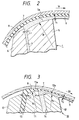
- FIG. 3 is an enlarged sectional view showing an doctor edge in another extrusion-type coating apparatus according to the invention.
- FIG. 4 is a graphical representation of a stretch flow coefficient with RF output in an Example 1.
- FIG. 5 is a graphical representation of a stretch flow coefficient with RF output in an Example 2.
- FIG. 6 is a graphical representation indicating a stretch flow coefficient with RF output in an Example 3.
- FIG. 1 illustrates an extrusion-type coating apparatus used to perform the method of the invention.
- the apparatus has an extrusion head 1 which is composed of a solution supplying system 2, a pocket 3, a slot 4, a doctor edge portion 5, and a back edge portion 6.
- a web 7, to which a lower-layer coating solution 8 has been applied in advance is continuously conveyed at a predetermined velocity (V1).
- the lower layer may be a magnetic coating solution or a non-magnetic coating solution.
- an upper-layer coating solution 9 is uniformly applied to the lower-layer coating solution 8 on the web while the lower layer is still wet.
- the solution 9 is applied with a thickness of t1 (wet thickness) of 4 ⁇ m or less.
- the solution supplying system 2 which is provided outside the extrusion head 1, is composed of metering pump (not shown) for continuously supplying the upper-layer coating solution 9 at a predetermined flow rate.
- the pump is connected through pipes with the pocket 3.
- the pocket 3 is formed in the extrusion head 1 in such a manner that the pocket 3 is extended in the direction of the width of the web 7.
- the slot 4 is a relatively narrow flow path formed in the body of the extrusion head 1 with an opening width (L1) extending in the direction of the width of web 7, much like pocket 3.
- the length of the opening in the direction of the width of web 7 is substantially equal to the coating width.
- the doctor edge portion 5 is located downstream of the opening of the slot 4 (as viewed in the direction of conveyance of the web 7), and it has an edge surface 5a which confronts the web 7.
- the edge surface 5a is curved in section with a radius of curvature R1.
- the back edge portion 6 is located upstream of the opening of the slot 4 (as viewed in the direction of conveyance of the web), and it has an edge surface which confronts the web 7.
- the average linear velocity v1 can be approximated or measured by other methods.
- the configuration of the extrusion head is not limiting.
- the technical concept of the invention can be applied to other extrusion heads which have different configurations than that described above.
- the upper-layer coating solution 9 is applied to the lower-layer coating solution 8 before the lower layer is dried.
- the lower-layer coating solution 8 and the upper-layer coating solution 9 may be applied to the web at the same time using the extrusion head 10, as shown in FIG. 3.
- the extrusion head 10 has a first slot 15, a second slot 14, a back edge portion 13, a first doctor edge portion 11, and a second doctor edge portion 12.
- a lower-layer coating solution 8, which may be either a magnetic coating solution or a non-magnetic coating solution, and an upper-layer coating solution 9 having a thickness (t2) of 4 ⁇ m or less, which is a magnetic coating solution, are uniformly applied to a web 7 while the web 7 is continuously conveyed at a predetermined velocity V2.
- the first slot 15 and the second slot 14 are relatively narrow flow paths which communicate with pockets (not shown) and which are formed in the body of the extrusion head 10 with opening widths L3 and L2, respectively, in such a manner that they extend in the direction of width of the web 7. It should be noted that the lengths of the openings in the direction of width of the web 7 are substantially equal to the coating widths of the corresponding layers 8 and 9.
- the first doctor edge portion 11 is located downstream of the opening of the first slot 15, as viewed in the direction of conveyance of the web 7, and has an edge surface 11a which confronts the web 7.
- the edge surface 11a is curved in section with a radius of curvature R3.
- the second doctor edge portion 12 is located downstream of the opening of the second slot 14, which is itself located downstream of the opening of the second slot 15, as viewed in the direction of conveyance of the web 7.
- Edge portion 12 has an edge surface 12a which confronts the web 7.
- the edge surface 12a is curved in section with a radius of curvature R2.
- the back edge portion 13 is located upstream of the opening of the slot 15, as viewed in the direction of conveyance of the web 7, and it has an edge surface which is confronted with the web 7.
- the average linear velocity v2 can be approximated or measured by other methods.
- Limiting the stretch flow coefficient ⁇ 2 regulates the fluidity of the upper-layer coating solution 9 near the opening of the slot 14 or downstream of it. That is, the dual coating conditions for providing excellent electromagnetic conversion characteristics can be determined best by defining the stretch flow coefficient of the upper-layer coating solution 9 when the solution has a thickness of 4 ⁇ m or less.
- the coating conditions can easily be controlled even when forming more than two layers of coating solution on the web simultaneously.
- the lower-layer coating solution 8 and the upper-layer coating solution 9 are applied directly to the web 7; however, they may be applied to an undercoat layer formed on the web 7 in advance and is either wet or dry.
- the flexible support (web) used in the method of the invention may be made of, for example, macromolecular film of polyethylene terephthalate and the like, paper, or metal.
- a magnetic coating solution is applied to the lower layer while the latter is still wet to form a magnetic layer.
- the magnetic layer thus formed is satisfactory in coating characteristic, and the magnetic recording medium thus manufactured is sufficiently high in electromagnetic conversion characteristic.
- Coating solutions A, B, C and D were prepared by mixing and dispersing the following components with a ball mill:
- Fe/Zn/Ni(92:4:4 in weight ratio) powder 300 parts by weight (acicular particles having an average particle size of 0.20 ⁇ m in the direction of long axis and a coercive force of 1600 Oe) vinyl chloride - vinyl acetate copolymer 30 parts by weight (copolymerization ratio 87:13, and copolymerization degree 400) electrically conductive carbon 20 parts by weight polyamide resin (amine value 300) 15 parts by weight lecithin 6 parts by weight silicon oil (dimethyl polysiloxane) 3 parts by weight cyclohexanone 300 parts by weight methyl ethyl ketone 300 parts by weight n-butanol 100 parts by weight
- the viscosity of the coating solution A was 0.9 poise with a shear rate of 5 ⁇ 102 sec ⁇ 1.
- ⁇ -Fe2O3 powder 300 parts by weight (acicular particles having an average particle size of 0.27 ⁇ m in the direction of long axis) vinyl chloride - vinyl acetate copolymer 30 parts by weight (copolymerization ratio 87:13, and copolymerization degree 400) electrically conductive carbon 20 parts by weight polyamide resin (amine value 300) 15 parts by weight lecithin 6 parts by weight silicon oil (dimethyl polysiloxane) 3 parts by weight xylol 300 parts by weight methyl isobutyl ketone 300 parts by weight n-butanol 100 parts by weight
- the viscosity of the coating solution B was 0.7 poise with a shear rate of 5 ⁇ 102 sec ⁇ 1.
- Fe/Zn/Ni(92:4:4 in weight ratio) powder 300 parts by weight (acicular particles having an average particle size of 0.20 ⁇ m in the direction of long axis, and a coercive force of 320 Oe) vinyl chloride - vinyl acetate copolymer 30 parts by weight (copolymerization ratio 87:13, and copolymerization degree 400) electrically conductive carbon 20 parts by weight polyamide resin (amine value 300) 15 parts by weight lecithin 6 parts by weight silicon oil (dimethyl polysiloxane) 3 parts by weight cyclohexanone 500 parts by weight n-butanol 100 parts by weight
- the viscosity of the coating solution C was 1.4 poise with a shear rate of 5 ⁇ 102 sec ⁇ 1.
- the viscosity of the coating solution D was 0.9 poise with a shear rate of 5 ⁇ 102 sec ⁇ 1.
- the above-described coating solution B (coating quantity 10 cc/m2) was applied to a polyethylene terephthalate flexible support (web), which was 10 ⁇ m in thickness and 300 mm in width, with the above-described extrusion head 1 to form a lower layer of coating solution on the web.
- the above-described coating solution A which was a magnetic coating solution, was applied to the lower layer of coating solution while the lower layer was still wet, using five different extrusion heads of the above-described type having respective widths L1 of 0.25 mm, 0.5 mm, 1.0 mm, 2.0 mm, and 3.0 mm.
- the coating solution was applied to form upper layers of coating solution on the web, thus providing different specimens.
- the coating conditions provided for the upper layers of coating solution were as follows. A tension applied to the web was 5 kg/300 mm width, the coating velocity V1 was varied between 300 m/min and 600 m/min, and the coating thickness t1 was varied among 4.0, 3.0, 2.0 and 1.0 ⁇ m. In each of the extrusion heads, the radius of curvature R1 of the doctor edge surface was 2.50 mm, and the width of the doctor edge (measured in the direction of conveyance of the web) was 0.75 mm.
- Specimens were formed under the same coating conditions as in the above-described Example 1, except that the coating solution B (coating quantity: 10 cc/m2) and the coating solution A, which was the magnetic coating solution, were simultaneously applied to a polyethylene terephthalate flexible support (web) 10 ⁇ m in thickness and 300 mm in width.
- the solutions were applied using the above-described extrusion head 10 to simultaneously form a lower layer of coating solution and an upper layer of coating solution on the web.
- five extrusion heads were used having a slot width L2 of the second slot of the extrusion heads set to 0.25 mm, 0.5 mm, 1.0 mm, 2.0 mm, and 3.0 mm, respectively.
- the radius of curvature R3 of the edge surface of the first doctor edge was 1.75 mm, and the width of the first doctor edge (measured in the direction of conveyance of the web) was 0.57 mm; for the second doctor edge, the radius of curvature R2 of the edge surface was 3.50 mm, and the width of the second doctor edge was 1.14 mm.
- Specimens were formed under the same coating conditions as those in the above-described Example 2, except that the coating solution D was used for formation of a lower layer of coating solution, while the coating solution C (the magnetic coating solution) was used for formation of an upper layer of coating solution.
- the stretch flow coefficient ⁇ of the magnetic coating solution should be 600 or less.
Landscapes
- Application Of Or Painting With Fluid Materials (AREA)
- Manufacturing Of Magnetic Record Carriers (AREA)
- Coating Apparatus (AREA)
Applications Claiming Priority (2)
| Application Number | Priority Date | Filing Date | Title |
|---|---|---|---|
| JP3235684A JP2630519B2 (ja) | 1991-08-23 | 1991-08-23 | 磁気記録媒体の製造方法 |
| JP235684/91 | 1991-08-23 |
Publications (2)
| Publication Number | Publication Date |
|---|---|
| EP0529516A1 true EP0529516A1 (de) | 1993-03-03 |
| EP0529516B1 EP0529516B1 (de) | 1998-01-28 |
Family
ID=16989681
Family Applications (1)
| Application Number | Title | Priority Date | Filing Date |
|---|---|---|---|
| EP92114235A Expired - Lifetime EP0529516B1 (de) | 1991-08-23 | 1992-08-20 | Verfahren zur Herstellung eines magnetischen Aufzeichnungsmediums |
Country Status (4)
| Country | Link |
|---|---|
| US (1) | US5304393A (de) |
| EP (1) | EP0529516B1 (de) |
| JP (1) | JP2630519B2 (de) |
| DE (1) | DE69224246T2 (de) |
Cited By (1)
| Publication number | Priority date | Publication date | Assignee | Title |
|---|---|---|---|---|
| FR2741285A1 (fr) * | 1995-11-21 | 1997-05-23 | Sony Corp | Applicateur a extrusion muni d'une filiere |
Families Citing this family (2)
| Publication number | Priority date | Publication date | Assignee | Title |
|---|---|---|---|---|
| DE19504930A1 (de) * | 1995-02-15 | 1996-08-22 | Basf Magnetics Gmbh | Vorrichtung zur Herstellung eines magnetischen Aufzeichnungsträgers |
| JP4264887B2 (ja) * | 2003-10-03 | 2009-05-20 | 富士フイルム株式会社 | 塗布方法 |
Citations (2)
| Publication number | Priority date | Publication date | Assignee | Title |
|---|---|---|---|---|
| US4332840A (en) * | 1979-07-23 | 1982-06-01 | Fuji Photo Film Co., Ltd. | Coating method |
| DE4008005A1 (de) * | 1989-03-13 | 1990-09-20 | Fuji Photo Film Co Ltd | Verfahren zum auftragen einer mehrzahl von fluessigkeiten auf einen sich kontinuierlich bewegenden, nichtmagnetischen traeger |
Family Cites Families (4)
| Publication number | Priority date | Publication date | Assignee | Title |
|---|---|---|---|---|
| NL220653A (de) * | 1956-09-11 | 1900-01-01 | ||
| JPS62121929A (ja) * | 1985-11-21 | 1987-06-03 | Fuji Photo Film Co Ltd | 磁気記録媒体の製造方法 |
| JPS62212933A (ja) * | 1986-03-13 | 1987-09-18 | Fuji Photo Film Co Ltd | 磁気記録媒体の製造方法 |
| JPH0693297B2 (ja) * | 1987-01-30 | 1994-11-16 | 富士写真フイルム株式会社 | 磁気記録媒体 |
-
1991
- 1991-08-23 JP JP3235684A patent/JP2630519B2/ja not_active Expired - Fee Related
-
1992
- 1992-08-20 EP EP92114235A patent/EP0529516B1/de not_active Expired - Lifetime
- 1992-08-20 US US07/932,688 patent/US5304393A/en not_active Expired - Lifetime
- 1992-08-20 DE DE69224246T patent/DE69224246T2/de not_active Expired - Lifetime
Patent Citations (2)
| Publication number | Priority date | Publication date | Assignee | Title |
|---|---|---|---|---|
| US4332840A (en) * | 1979-07-23 | 1982-06-01 | Fuji Photo Film Co., Ltd. | Coating method |
| DE4008005A1 (de) * | 1989-03-13 | 1990-09-20 | Fuji Photo Film Co Ltd | Verfahren zum auftragen einer mehrzahl von fluessigkeiten auf einen sich kontinuierlich bewegenden, nichtmagnetischen traeger |
Cited By (1)
| Publication number | Priority date | Publication date | Assignee | Title |
|---|---|---|---|---|
| FR2741285A1 (fr) * | 1995-11-21 | 1997-05-23 | Sony Corp | Applicateur a extrusion muni d'une filiere |
Also Published As
| Publication number | Publication date |
|---|---|
| JP2630519B2 (ja) | 1997-07-16 |
| US5304393A (en) | 1994-04-19 |
| EP0529516B1 (de) | 1998-01-28 |
| DE69224246T2 (de) | 1998-05-14 |
| DE69224246D1 (de) | 1998-03-05 |
| JPH05208165A (ja) | 1993-08-20 |
Similar Documents
| Publication | Publication Date | Title |
|---|---|---|
| US4465707A (en) | Coating method | |
| US4907530A (en) | Apparatus for applying a liquid to a support | |
| JP3445343B2 (ja) | 塗布方法および塗布装置 | |
| US5083524A (en) | Apparatus for applying magnetic liquid to moving web | |
| EP0388818A2 (de) | Beschichtungsvorrichtung | |
| JP3032808B2 (ja) | 磁気記録媒体の製造方法 | |
| US5501737A (en) | Coating method and apparatus having an exchangeable resisting body insertable in the reservoir | |
| JP2630522B2 (ja) | 塗布方法及び装置 | |
| US5167713A (en) | Coating apparatus | |
| EP0529516B1 (de) | Verfahren zur Herstellung eines magnetischen Aufzeichnungsmediums | |
| US4994306A (en) | Method for applying plural liquids to continuously moving nonmagnetic carrier | |
| EP0673684B1 (de) | Extrusionsbeschichtungskopf | |
| EP0451841B1 (de) | Vorrichtung zum Auftragen einer Flüssigkeit auf einen flexiblen Träger | |
| US6730359B2 (en) | Method for coating a running web using a plurality of coating liquids | |
| US5188907A (en) | Magnetic recording medium | |
| US5209954A (en) | Method for applying a coating liquid to a web | |
| EP0539724A1 (de) | Vorrichtung zur Extrusionsbeschichtung | |
| US6447611B1 (en) | Coating apparatus | |
| US5215803A (en) | Magnetic recording medium | |
| JP2623897B2 (ja) | 磁気記録媒体の製造方法 | |
| US20030054095A1 (en) | Method of deciding coating condition in manufacturing magnetic recording medium and magnetic recording medium | |
| JP2748014B2 (ja) | 磁気記録媒体、その製造方法及び製造装置 | |
| US5147720A (en) | Magnetic recording medium comprising a magnetic layer and a backcoat layer | |
| US5460876A (en) | Magnetic recording medium | |
| JP2860598B2 (ja) | 磁気記録媒体 |
Legal Events
| Date | Code | Title | Description |
|---|---|---|---|
| PUAI | Public reference made under article 153(3) epc to a published international application that has entered the european phase |
Free format text: ORIGINAL CODE: 0009012 |
|
| AK | Designated contracting states |
Kind code of ref document: A1 Designated state(s): DE FR GB |
|
| 17P | Request for examination filed |
Effective date: 19930212 |
|
| 17Q | First examination report despatched |
Effective date: 19950922 |
|
| GRAG | Despatch of communication of intention to grant |
Free format text: ORIGINAL CODE: EPIDOS AGRA |
|
| GRAG | Despatch of communication of intention to grant |
Free format text: ORIGINAL CODE: EPIDOS AGRA |
|
| GRAH | Despatch of communication of intention to grant a patent |
Free format text: ORIGINAL CODE: EPIDOS IGRA |
|
| GRAH | Despatch of communication of intention to grant a patent |
Free format text: ORIGINAL CODE: EPIDOS IGRA |
|
| GRAA | (expected) grant |
Free format text: ORIGINAL CODE: 0009210 |
|
| AK | Designated contracting states |
Kind code of ref document: B1 Designated state(s): DE FR GB |
|
| REF | Corresponds to: |
Ref document number: 69224246 Country of ref document: DE Date of ref document: 19980305 |
|
| ET | Fr: translation filed | ||
| PG25 | Lapsed in a contracting state [announced via postgrant information from national office to epo] |
Ref country code: GB Free format text: LAPSE BECAUSE OF NON-PAYMENT OF DUE FEES Effective date: 19980820 |
|
| PLBE | No opposition filed within time limit |
Free format text: ORIGINAL CODE: 0009261 |
|
| 26N | No opposition filed | ||
| GBPC | Gb: european patent ceased through non-payment of renewal fee |
Effective date: 19980820 |
|
| REG | Reference to a national code |
Ref country code: FR Ref legal event code: TP Ref country code: FR Ref legal event code: CD |
|
| PGFP | Annual fee paid to national office [announced via postgrant information from national office to epo] |
Ref country code: DE Payment date: 20110727 Year of fee payment: 20 Ref country code: FR Payment date: 20110818 Year of fee payment: 20 |
|
| REG | Reference to a national code |
Ref country code: DE Ref legal event code: R071 Ref document number: 69224246 Country of ref document: DE |
|
| REG | Reference to a national code |
Ref country code: DE Ref legal event code: R071 Ref document number: 69224246 Country of ref document: DE |
|
| PG25 | Lapsed in a contracting state [announced via postgrant information from national office to epo] |
Ref country code: DE Free format text: LAPSE BECAUSE OF EXPIRATION OF PROTECTION Effective date: 20120821 |