EP0529527B1 - Procédé et appareil d'imagerie rapide par résonance magnétique à qualité d'image améliorée - Google Patents
Procédé et appareil d'imagerie rapide par résonance magnétique à qualité d'image améliorée Download PDFInfo
- Publication number
- EP0529527B1 EP0529527B1 EP92114303A EP92114303A EP0529527B1 EP 0529527 B1 EP0529527 B1 EP 0529527B1 EP 92114303 A EP92114303 A EP 92114303A EP 92114303 A EP92114303 A EP 92114303A EP 0529527 B1 EP0529527 B1 EP 0529527B1
- Authority
- EP
- European Patent Office
- Prior art keywords
- magnetic field
- gradient magnetic
- pulse sequence
- phase encoding
- echo signals
- Prior art date
- Legal status (The legal status is an assumption and is not a legal conclusion. Google has not performed a legal analysis and makes no representation as to the accuracy of the status listed.)
- Expired - Lifetime
Links
Images


Classifications
-
- G—PHYSICS
- G01—MEASURING; TESTING
- G01R—MEASURING ELECTRIC VARIABLES; MEASURING MAGNETIC VARIABLES
- G01R33/00—Arrangements or instruments for measuring magnetic variables
- G01R33/20—Arrangements or instruments for measuring magnetic variables involving magnetic resonance
- G01R33/44—Arrangements or instruments for measuring magnetic variables involving magnetic resonance using nuclear magnetic resonance [NMR]
- G01R33/48—NMR imaging systems
- G01R33/54—Signal processing systems, e.g. using pulse sequences ; Generation or control of pulse sequences; Operator console
- G01R33/56—Image enhancement or correction, e.g. subtraction or averaging techniques, e.g. improvement of signal-to-noise ratio and resolution
- G01R33/561—Image enhancement or correction, e.g. subtraction or averaging techniques, e.g. improvement of signal-to-noise ratio and resolution by reduction of the scanning time, i.e. fast acquiring systems, e.g. using echo-planar pulse sequences
- G01R33/5615—Echo train techniques involving acquiring plural, differently encoded, echo signals after one RF excitation, e.g. using gradient refocusing in echo planar imaging [EPI], RF refocusing in rapid acquisition with relaxation enhancement [RARE] or using both RF and gradient refocusing in gradient and spin echo imaging [GRASE]
- G01R33/5616—Echo train techniques involving acquiring plural, differently encoded, echo signals after one RF excitation, e.g. using gradient refocusing in echo planar imaging [EPI], RF refocusing in rapid acquisition with relaxation enhancement [RARE] or using both RF and gradient refocusing in gradient and spin echo imaging [GRASE] using gradient refocusing, e.g. EPI
-
- G—PHYSICS
- G01—MEASURING; TESTING
- G01R—MEASURING ELECTRIC VARIABLES; MEASURING MAGNETIC VARIABLES
- G01R33/00—Arrangements or instruments for measuring magnetic variables
- G01R33/20—Arrangements or instruments for measuring magnetic variables involving magnetic resonance
- G01R33/44—Arrangements or instruments for measuring magnetic variables involving magnetic resonance using nuclear magnetic resonance [NMR]
- G01R33/48—NMR imaging systems
- G01R33/54—Signal processing systems, e.g. using pulse sequences ; Generation or control of pulse sequences; Operator console
- G01R33/56—Image enhancement or correction, e.g. subtraction or averaging techniques, e.g. improvement of signal-to-noise ratio and resolution
- G01R33/561—Image enhancement or correction, e.g. subtraction or averaging techniques, e.g. improvement of signal-to-noise ratio and resolution by reduction of the scanning time, i.e. fast acquiring systems, e.g. using echo-planar pulse sequences
- G01R33/5615—Echo train techniques involving acquiring plural, differently encoded, echo signals after one RF excitation, e.g. using gradient refocusing in echo planar imaging [EPI], RF refocusing in rapid acquisition with relaxation enhancement [RARE] or using both RF and gradient refocusing in gradient and spin echo imaging [GRASE]
- G01R33/5618—Echo train techniques involving acquiring plural, differently encoded, echo signals after one RF excitation, e.g. using gradient refocusing in echo planar imaging [EPI], RF refocusing in rapid acquisition with relaxation enhancement [RARE] or using both RF and gradient refocusing in gradient and spin echo imaging [GRASE] using both RF and gradient refocusing, e.g. GRASE
-
- G—PHYSICS
- G01—MEASURING; TESTING
- G01R—MEASURING ELECTRIC VARIABLES; MEASURING MAGNETIC VARIABLES
- G01R33/00—Arrangements or instruments for measuring magnetic variables
- G01R33/20—Arrangements or instruments for measuring magnetic variables involving magnetic resonance
- G01R33/44—Arrangements or instruments for measuring magnetic variables involving magnetic resonance using nuclear magnetic resonance [NMR]
- G01R33/48—NMR imaging systems
- G01R33/54—Signal processing systems, e.g. using pulse sequences ; Generation or control of pulse sequences; Operator console
- G01R33/56—Image enhancement or correction, e.g. subtraction or averaging techniques, e.g. improvement of signal-to-noise ratio and resolution
- G01R33/565—Correction of image distortions, e.g. due to magnetic field inhomogeneities
- G01R33/56554—Correction of image distortions, e.g. due to magnetic field inhomogeneities caused by acquiring plural, differently encoded echo signals after one RF excitation, e.g. correction for readout gradients of alternating polarity in EPI
Definitions
- the present invention relates to a method of magnetic resonance imaging according to the preamble of claim 1. Further, the present invention relates to an apparatus for magnetic resonance imaging according to the preamble of claim 14.
- magnetic resonance imaging is a method for visualizing microscopic chemical and physical information of an object to be examined by utilizing the phenomenon that a group of nuclear spins having characteristic magnetic moments, located within a homogeneous static magnetic field, makes the resonant absorption of the energy of the high frequency magnetic field rotating at the specific frequency around the body to be examined.
- NMR nuclear magnetic resonance
- the imaging time for completing the imaging process can be as short as 50 ms to 10 sec.
- the conventional high speed imaging methods such as FLASH imaging have the further shortcoming in that the contrast becomes poor in the T 2 enhanced image, T 1 enhanced image, and spin density image, which can be obtained by using the conventionally known spin echo pulse sequence.
- the mosaic scan imaging method and the hybrid imaging method are unable to resolve the problems of the influence of the inhomogeneity of the static magnetic field, the chemical shift artifacts, and the poor contrast in the T 2 enhanced image, T 1 enhanced image, and spin density image.
- an apparatus for magnetic resonance imaging according to claim 14.
- Fig. 1 is block diagram of one embodiment of a magnetic resonance imaging apparatus for implementing the method of magnetic resonance imaging according to the present invention.
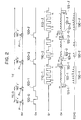
- Fig. 2 is a timing chart for the pulse sequence according to the first embodiment of the method of magnetic resonance imaging according to the present invention.
- Fig. 3 is a diagram of the k-space trajectory for indicating an order of data acquisition in the first embodiment using the pulse sequence of Fig. 2.
- Figs. 4A and 4B are diagrammatic illustration of two possible data acquisition pattern that can be used in the first embodiment using the pulse sequence of Fig. 2.
- Figs. 5A and 5B are diagrammatic illustration of two possible k-space segmentation pattern that can be used in the first embodiment using the pulse sequence of Fig. 2.
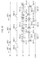
- Fig. 6 is a timing chart for the pulse sequence according to the second embodiment of the method of magnetic resonance imaging according to the present invention.
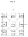
- Fig. 7 is a diagram of the k-space trajectory for indicating an order of data acquisition in the second embodiment using the pulse sequence of Fig. 6.
- Fig. 8 is a timing chart for the pulse sequence according to the third embodiment of the method of magnetic resonance imaging according to the present invention.
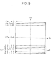
- Fig. 9 is a diagram of the k-space trajectory for indicating an order of data acquisition in the third embodiment using the pulse sequence of Fig. 8.
- Fig. 10 is a timing chart for the pulse sequence according to the fourth embodiment of the method of magnetic resonance imaging according to the present invention.
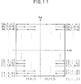
- Fig. 11 is a diagram of the k-space trajectory for indicating an order of data acquisition in the fourth embodiment using the pulse sequence of Fig. 10.
- Fig. 12 is a timing chart for the pulse sequence according to the fifth embodiment of the method of magnetic resonance imaging according to the present invention.
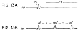
- Figs. 13A and 13B are timing charts of two possible pre-pulse sequences that can be used in the sixth embodiment of the method of magnetic resonance imaging according to the present invention.
- Fig. 14 is a timing chart for the pulse sequence according to the seventh embodiment of the method of magnetic resonance imaging according to the present invention.
- MR magnetic resonance
- the magnetic resonance imaging apparatus comprises: a main magnet 1 for producing a static magnetic field; a main magnet power source 2 for supplying power to the main magnet 1; shim coils 3 for adjusting the homogeneity of the static magnetic field produced by the main magnet 1; shim coil power sources 4 for supplying power to the shim coil 3; gradient coils 5 for producing gradient magnetic fields in X-, Y-, and Z-directions; gradient coil power sources 6 for supplying power to the gradient coils 6; a bed 8 for mounting a body to be examined 7 in the static magnetic field produced by the main magnet 1 and the gradient magnetic fields produced by the gradient coils 5; a probe 9 for transmitting RF pulses onto the body to be examined 7 and receiving nuclear magnetic resonance (NMR) signals emitted from the body to be examined 7; a transmitter unit 10 for supplying the RF pulses to be transmitted from the probe 9; a receiver unit 11 for applying the orthogonal phase detection to the NMR signals received by the probe 9 to obtain MR image data; a
- This magnetic resonance imaging apparatus can be operated under the appropriate coordination by the system controller 12 to implement the various embodiments of the method of magnetic resonance imaging according to the present invention by carrying out the various pulse sequences, each of which will now be described in detail.
- RF stands for the RF pulses
- Gs, Gr, and Ge stand for the gradient magnetic fields used for slicing of desired imaging slice plane in the body to be examined 7, reading of the NMR signals from the body to be examined 7, and encoding of position information in the imaging slice plane as phase information in the NMR signals, respectively
- Fig. 2 the pulse sequence implementing the first embodiment of the method of magnetic resonance imaging according to the present invention will be described in detail.
- the first 180° RF pulse P 2 pointing in the y'-direction in the rotational coordinates is applied from the probe 9 after an elapse of TE/2 from a center of the 90° RF pulse P 1 , where TE is an echo time, while the slicing gradient magnetic field 100-1 is applied by the gradient coils 5.
- the varying phases of the nuclear spins produced by the inhomogeneity of the static magnetic field or the static magnetic field off-set are inverted with respect to the y'-axis of the rotational coordinates, such that the echo signals are produced after an elapse of TE/2 from the center of the first 180° RF pulse P 2 as the phases of the nuclear spins get aligned.
- the first m-step initial phase encoding gradient magnetic field 121-1 is applied from the gradient coils 5, and the first series of the reading gradient magnetic field 110-1 which is regularly fluctuating between positive value and negative value for n times is applied by the gradient coils 5, while at the same time the first series of pulse shaped phase encoding gradient magnetic field 122-1 is applied during the switching intervals in response to the application of the first series of the reading gradient magnetic field 110-1, so as to collect the echo signal data sequence given by the echo signals 130-1.
- the first rewinding phase encoding gradient magnetic field 123-1 for making the integrated value of the phase encoding gradient magnetic fields equal to zero or a predetermined constant value is applied, so as to rewind the phases of the gradient magnetic fields to the initial state.
- the second 180° RF pulse P 3 pointing in the y'-direction in the rotational coordinates is applied from the probe 9, while the slicing gradient magnetic field 100-2 is applied by the gradient coils 5.
- the second m-step initial phase encoding gradient magnetic field 121-2 is applied from the gradient coils 5, and the second series of the reading gradient magnetic field 110-2 which is regularly fluctuating between positive value and negative value for n times is applied by the gradient coils 5, while at the same time the second series of the pulse shaped phase encoding gradient magnetic field 122-2 is applied during the switching intervals in response to the application of the second series of the reading gradient magnetic field 110-2, so as to collect the echo signal data sequence given by the echo signals 130-2.
- the second initial phase encoding gradient magnetic field 121-2 has the value different from that of the first initial phase encoding gradient magnetic field 121-1 used in obtaining the data for the first region 21 in the k-space.
- the second rewinding phase encoding gradient magnetic field 123-2 for making the integrated value of the phase encoding gradient magnetic fields equal to zero or a predetermined constant value is applied, so as to rewind the phases of the gradient magnetic fields to the initial state.
- the second rewinding phase encoding gradient magnetic field 123-2 has the value different from that of the first rewinding phase encoding gradient magnetic field 123-1 used in obtaining the data for the first region 21 in the k-space, in correspondence to the difference between the second initial phase encoding gradient magnetic field 121-2 and the first initial phase encoding gradient magnetic field 121-1.
- the process similar to that described above for obtaining the data for the second region 22 in the k-space is repeated up to the l-th echo signal data sequence given by the echo signals 130-l.
- the values of the initial phase encoding gradient magnetic field 121 and the corresponding rewinding phase encoding gradient magnetic field 123 for obtaining each echo signal data sequence are set to be different from the values used for the previous echo signal data sequences, as shown in Fig. 2.
- the entire pulse sequence of Fig. 2 as described above is repeated for m times, with the values of the initial phase encoding gradient magnetic field 121 and the corresponding rewinding phase encoding gradient magnetic field 123 for obtaining each of the first to l-th echo signal data sequence sequentially changed among m different settings, so as to obtain the data for the subsequent regions in the k-space.
- the process similar to that described above for obtaining one block of echo signals by using a series of the reading gradient magnetic field and a series of phase encoding gradient magnetic field is repeated for l ⁇ m times in order to obtain all the data in all the regions in the k-space.
- the desired MR image can be obtained by rearranging the data in the k-space according to the data acquisition pattern specified by the initial phase encoding gradient magnetic field 121, and applying the inverse 2D Fourier transformation to the rearranged data.
- the k-space is divided into a plurality of regions and the data are collected for each of the regions in the k-space separately, so that the image quality of the obtained MR image such as the spatial resolution and the S/N ratio can be improved, as the echo signals having less dissipation are used in obtaining the data for each of the regions in the k-space.
- the initial phase encoding gradient magnetic field 121 is gradually increased step by step from the process for obtaining the data for the first region in the k-space onward
- the pattern of changing of the initial phase encoding gradient magnetic field 121 may be different from such a pattern shown in Fig. 2, and any desirable pattern can be used according to the need.
- the influence due to the inhomogeneity of the static magnetic field is minimum at a point after an elapse of TE/2 since the application of each 180° RF pulse, so that the image quality of the obtained MR image can be further improved by appropriately adjusting the data acquisition pattern specified by the initial phase encoding gradient magnetic field 121 such that the data obtained after an elapse of TE/2 since the application of each 180° RF pulse are located in a vicinity of the origin on the k-space.
- the order of data acquisition realized in the k-space shown in Fig. 3 indicates the data acquisitions to proceed along a zigzag trajectory in the k-space as shown in Fig. 4A
- the data acquisition may be carried out to proceed along an interlaced trajectory in the k-space as shown in Fig. 4B alternatively.
- the CPMG (Carr-Purcell-Meiboom-Gill) RF pulse sequence of 90°(x') ⁇ 180°(y') ⁇ 180°(y') ⁇ ............ is used for the RF pulses in the pulse sequence shown in Fig. 2
- the other pulse sequence for the RF pulses such as modified CP (Carr-Purcell) RF pulse sequence of 90° (x') ⁇ 180° (x') ⁇ 180° (x') ⁇ ............ or any other desired RF pulse sequence may be used instead.
- the data acquisition procedure for obtaining all the data on the k-space as described above may be replaced by the so called half encoding scheme in which the data are obtained for only the half of the k-space and the remaining half of the data are derived as the complex conjugates of the obtained data.
- the imaging time can be reduced in half.
- the repetition interval of the entire pulse sequence i.e., a period between the application of the 90° RF pulse for one pulse sequence to the application of the 90° RF pulse for another pulse sequence
- the initial phase encoding gradient magnetic field so as to realize the pattern of the segmentation of the k-space as shown in Fig. 5A in which the data reflecting the transverse relaxation time T2 of the nuclear spins are located in a vicinity of the origin on the k-space
- This pulse sequence of Fig. 6 differs from the pulse sequence of Fig. 2 in that, prior to the application of the reading gradient magnetic field 110, i-step off-set reading gradient magnetic field 111 is also applied, and after the application of the reading gradient magnetic field 110, i-step off-set cancelling gradient magnetic field 112 is also applied.
- the remaining features of this pulse sequence of Fig. 6 are substantially similar to those of Fig. 2.
- the entire pulse sequence of Fig. 6 is repeated for m ⁇ i times, with the values of the initial phase encoding gradient magnetic field 121 and the corresponding rewinding phase encoding gradient magnetic field 123 for obtaining each of the first to l-th echo signal data sequence sequentially changed among m different settings, and the values of the off-set reading gradient magnetic field 111 and the off-set cancelling gradient magnetic field 112 for obtaining each of the first to l-th echo signal data sequence sequentially changed among i different settings, so as to obtain the data for the subsequent regions in the k-space.
- the data acquisition using this pulse sequence of Fig. 6 proceeds in units of blocks in both the encoding and reading gradient magnetic field directions on the k-space, as indicated in Fig. 7.
- the k-space is more finely divided into a plurality of blocks and the data are collected for each of the blocks in the k-space separately, so that the image quality of the obtained NMR image such as the spatial resolution and the S/N ratio can be even more improved compared with the first embodiment described above, as the echo signals having even less dissipation are used in obtaining the data for each of the blocks in the k-space.
- the m-step initial phase encoding gradient magnetic field 221 is applied from the gradient coils 5, and the reading gradient magnetic field 210 which is regularly fluctuating between positive value and negative value for n times is applied by the gradient coils 5, while at the same time the pulse shaped phase encoding gradient magnetic field 222 is applied during the switching intervals in response to the application of the reading gradient magnetic field 210, so as to collect the FID echo signal data sequence given by the echo signals 230.
- the entire pulse sequence of Fig. 8 is repeated for m times, with the values of the initial phase encoding gradient magnetic field 221 for obtaining each echo signal data sequence sequentially changed among m different settings, so as to obtain the data for the subsequent regions in the k-space.
- the desired MR image can be obtained by rearranging the data in the k-space according to the data acquisition pattern specified by the initial phase encoding gradient magnetic field 221, and applying the inverse 2D Fourier transformation to the rearranged data.
- the k-space is divided into a plurality of regions and the data are collected for each of the regions in the k-space separately, so that the image quality of the obtained MR image such as the spatial resolution and the S/N ratio can be improved, as the echo signals having less dissipation are used in obtaining the data for each of the regions in the k-space, just as in the first embodiment described above.
- the dispersion of the phases of the nuclear spins due to the inhomogeneity of the static magnetic field increases after the application of the ⁇ ° RF pulse P 5 as the time elapses, and this in turn causes the disturbance or the lowering of the resolution in the reconstructed image, so that the image quality of the obtained MR image can be further improved by appropriately adjusting the data acquisition pattern specified by the initial phase encoding gradient magnetic field 221 such that the data obtained immediately after the application of the ⁇ ° RF pulse P 5 are located in a vicinity of the origin on the k-space.
- This pulse sequence of Fig. 10 differs from the pulse sequence of Fig. 8 in that, prior to the application of the reading gradient magnetic field 210, i-step off-set reading gradient magnetic field 211 is also applied.
- the remaining features of this pulse sequence of Fig. 10 are substantially similar to those of Fig. 8.
- the enitre pulse sequence of Fig. 10 is repeated for m ⁇ i times, with the values of the initial phase encoding gradient magnetic field 221 for obtaining each echo signal data sequence sequentially changed among m different settings, and the values of the off-set reading gradient magnetic field 211 for obtaining each echo signal data sequence sequentially changed among i different settings, so as to obtain the data for the subsequent regions in the k-space.
- the data acquisition using this pulse sequence of Fig. 10 proceeds in units of blocks in both the encoding and reading gradient magnetic field directions on the k-space as indicated in Fig. 11.
- the k-space is more finely divided into a plurality of blocks and the data are collected for each of the blocks in the k-space separately, so that the image quality of the obtained MR image such as the spatial resolution and the S/N ratio can be even more improved compared with the third embodiment described above, as the echo signals having even less dissipation are used in obtaining the data for each of the blocks in the k-space.
- the dispersion of the phases of the nuclear spins due to the inhomogeneity of the static magnetic field increases after the application of the ⁇ ° RF pulse P 5 as the time elapses, and this in turn causes the disturbance or the lowering of the resolution in the reconstructed image, so that the image quality of the obtained MR image can be further improved by appropriately adjusting the data acquisition pattern specified by the initial phase encoding gradient magnetic field 221 such that the data obtained immediately after the application of the ⁇ ° RF pulse P 5 are located in a vicinity of the origin on the k-space.
- This pulse sequence of Fig. 12 differs from the pulse sequence of Fig. 2 in that, in the process of obtaining the data, immediately after the application of the slicing gradient magnetic field 100, i-step off-set slice phase encoding gradient magnetic field 101 is also applied, and immediately before the next application of the slicing gradient magnetic field 100, i-step phase off-set rewinding gradient magnetic field 102 is also applied.
- the remaining features of this pulse sequence of Fig. 12 are substantially similar to those of Fig. 2.
- the entire pulse sequence of Fig. 12 is repeated for m ⁇ i times, with the values of the initial phase encoding gradient magnetic field 121 and the corresponding rewinding phase encoding gradient magnetic field 123 for obtaining each of the first to l-th echo signal data sequence sequentially changed among m different settings, and the values of the off-set slice phase encoding gradient magnetic field 101 and the corresponding phase off-set rewinding gradient magnetic field 102 for obtaining each of the first to l-th echo signal data sequence sequentially changed among i different settings, so as to obtain the data for the subsequent regions in the k-space.
- Figs. 13A and 13B the pulse sequence implementing the sixth embodiment of the method of magnetic resonance imaging according to the present invention will be described in detail.
- the execution of any one of the pulse sequences of the first to fifth embodiments described above is preceded by the execution of a pre-pulse sequence for obtaining the image having a desired contrast, such as the pre-pulse sequences shown in Fig. 13A and Fig. 13B.
- the pre-pulse sequence shown in Fig. 13A is for obtaining the T1 enhanced image, and comprises a 180° inversion pulse P 6 for invertedly exciting the nuclear spins, followed by the predetermined interval period TI.
- the pre-pulse sequence shown in Fig, 13B is for obtaining the T2 enhanced image, and comprises a sequence of 90°- ⁇ -180°- ⁇ -90° pulses.
- any other known pre-pulse sequence for obtaining the image having a special contrast may be used instead of the pre-pulse sequences of Figs. 13A and 13B, according to the need.
- the m-step initial phase encoding gradient magnetic field 321 is applied from the gradient coils 5, and the reading gradient magnetic field 310 which is regularly fluctuating between positive value and negative value for n times is applied by the gradient coils 5, while at the same time the pulse shaped phase encoding gradient magnetic field 322 is applied during the switching intervals in response to the application of the reading gradient magnetic field 310, so as to collect the FID echo signal data sequence given by the echo signals 330.
- the rewinding phase encoding gradient magnetic field 323 for making the integrated value of the phase encoding gradient magnetic field equal to zero or a predetermined constant value is applied, so as to rewind the phases of the gradient magnetic fields to the initial state.
- the entire pulse sequence of Fig. 14 is repeated for m times, with the values of the initial phase encoding gradient magnetic field 321 and the corresponding rewinding phase encoding gradient magnetic field 323 for obtaining each echo signal data sequence sequentially changed among m different settings, so as to obtain the data for the subsequent regions in the k-space.
- the repetition of the pulse sequence can be carried out more quickly without waiting for the entire longitudinal relaxation time T1 during which the recovery of the longitudinal magnetization components can be made naturally.
- the pre-processing it is necessary to collect the echo signal data sequence without using the phase encoding gradient magnetic field Ge as well as the off-set slice phase encoding gradient magnetic field and the off-set reading gradient magnetic field if any of these are to be used, to determine the peak position of the echo signals and the amplitude at the peak position of the echo signals as the reference data. Then, any one or all of the data order, amplitudes, and phases of the echo signals data should be corrected according to the obtained reference data on the echo signals.
- the data sequence to be used in determining the reference data may be collected either from the imaging target of the body to be examined 7 or from the appropriate phantom.
- the post-processing it is necessary to measure the homogeneity of the static magnetic field on the imaging target of the body to be examined 7, and to make the appropriate correction of the influence due to the inhomogeneity of the static magnetic field such as the distortion of the image.
- the imaging target of the body to be examined 7 is made of a material which possesses a plurality of nuclear magnetic resonance frequencies due to the chemical shift
- a pre-pulse sequence for chemical shift suppression including: CHESS scheme (see, A.Hasse et al. "1H-NMR Chemical Shift Selective (CHESS) Imaging", Physics in Medicine and Biology, Vol. 30, pp.
Landscapes
- Physics & Mathematics (AREA)
- Health & Medical Sciences (AREA)
- General Health & Medical Sciences (AREA)
- Nuclear Medicine, Radiotherapy & Molecular Imaging (AREA)
- Radiology & Medical Imaging (AREA)
- Engineering & Computer Science (AREA)
- Signal Processing (AREA)
- High Energy & Nuclear Physics (AREA)
- Condensed Matter Physics & Semiconductors (AREA)
- General Physics & Mathematics (AREA)
- Magnetic Resonance Imaging Apparatus (AREA)
Claims (28)
- Procédé de formation d'une image de résonance magnétique, comprenant les étapes consistant à :caractérisé en ce que(a) placer un objet à examiner dans un champ magnétique statique (1, 2, 3);(b) mettre en oeuvre une séquence de pulsations, comprenant:(b1) l'application d'une pulsation RF (RF, P1, P2,..., Pl+1) et d'un gradient de champ magnétique de sélection de tranche (Gs, 100-0, 100-1,...,. 100-l) pour exciter ou refocaliser une région de formation d'image souhaitée dans le corps à examiner;(b2) l'application au corps à examiner d'un gradient de champ magnétique de lecture (Gr, 110-1, 110-2,..., 110-l) qui fluctue régulièrement entre une valeur négative et une valeur positive;(b3) l'application d'un gradient initial de champ magnétique de codage en phase (Ge, 121-1, 121-2,..., 121-l) au corps à examiner avant que le gradient de champ magnétique de lecture ne soit appliqué à l'étape (b2);(b4) l'application d'un gradient prédéterminé de champ magnétique pulsé de codage en phase (122-1, ..., 122-l) au corps à examiner, chaque fois que le gradient de champ magnétique de lecture change de polarité;(b5) la collecte de signaux d'écho (130-1,..., 130-l) pour la région partielle (21, 22,..., lxm) de l'ensemble de l'espace k émis par la région de formation d'image voulue, un certain temps après que le gradient de champ magnétique de lecture ait changé de polarité;(c) répéter plusieurs fois la séquence de pulsations de l'étape (b), en changeant de manière séquentielle les paramètres du gradient de champ magnétique de codage en phase (121-1, ..., 121-l) appliqué à l'étape (b3) de telle façon quec1) les signaux d'écho sont collectés séquentiellement dans des blocs d'échos RF qui remplissent tout l'espace k,c2) chaque bloc d'écho continu contient une pluralité d'échos de gradients consécutifs; et(d) reconstruire des images MR à partir des signaux d'écho collectés séquentiellement pour tout l'espace k, qui sont collectés à l'étape (c), par l'application répétée de la séquence de pulsations de l'étape (b);(c1) le changement des paramètres du gradient initial de champ magnétique de codage en phase (121-1, ..., 121-l) est fait de telle façon que les signaux d'écho sont collectés séquentiellement pour des blocs d'échos RF continus (21, 22, ..., lxm),(c2) lesdits blocs d'échos RF continus sont agencés le long d'une direction de codage en phase de l'espace k.
- Procédé selon la revendication 1, dans lequel l'étape (b1) de la séquence de pulsations de l'étape (b) comprend de plus:(b1-1) l'application d'une pulsation RF 90° et du gradient de champ magnétique de sélection de tranche pour exciter la région de formation d'image souhaitée dans le corps à examiner; et(b1-2) l'application d'une pulsation RF 180° de refocalisation ensemble avec le gradient de champ magnétique de sélection de tranche;et dans lequel la séquence de pulsations à l'étape (b) comprend de plus l'étape consistant à répéter plusieurs fois les étapes (b1-2) et (b2) à (b5), les paramètres du gradient initial de champ magnétique de codage en phase appliqué à l'étape (b3) étant différents à chaque répétition de l'étape (b3)
- Procédé selon la revendication 1, dans lequel la séquence de pulsations de l'étape(b) comprend de plus:
(b6) l'application d'un gradient de champ magnétique de codage en phase de rétablissement, pour amener à une valeur constante prédéterminée, une valeur intégrée du gradient de champ magnétique de codage en phase appliqué au corps à examiner, après que les signaux d'écho ont été collectés à l'étape (b5), avant que la séquence. de pulsations de l'étape (b) soit répétée la fois suivante. - Procédé selon la revendication 1, dans lequel la séquence de pulsations de l'étape (b) comprend de plus:(b7) l'application au corps à examiner, d'un gradient de champ magnétique de lecture décalé (111-1, ..., 111-l) pour diviser la région partielle dans l'espace k en une pluralité de parties dans la direction du gradient de champ magnétique de lecture de l'espace k, avant que le gradient de champ magnétique de lecture ne soit appliqué à l'étape (b3);(b8) l'application d'un gradient de champ magnétique d'annulation du décalage (112-1, ..., 112-l) pour supprimer le gradient de champ magnétique de lecture décalé appliqué à l'étape (b7) après que les signaux d'écho ont été collectés à l'étape (b5), avant que la séquence de pulsations de l'étape (b) soit répétée la fois suivante.
- Procédé selon la revendication 1, dans lequel la séquence de pulsations de l'étape (b) comprend de plus:(b9) l'application au corps à examiner, d'un gradient de champ magnétique de codage en phase décalé (101-1, ..., 101-l) dans l'axe du gradient de tranche choisi avant que le gradient de champ magnétique de lecture ne soit appliqué à l'étape (b3); et(b10) l'application d'un gradient de champ magnétique d'annulation du décalage en phase(102-1, ..., 102-l) pour annuler le gradient de champ magnétique de codage en phase décalé appliqué à l'étape (b9), après que les signaux d'écho ont été collectés à l'étape (b5), avant que la séquence de pulsations de l'étape (b) soit répétée la fois suivante.
- Procédé selon la revendication 1, dans lequel, à l'étape (b1), les pulsations RF sont appliquées suivant l'un des schémas CPMG (Carr-Purcell-Meiboom-Gill) et CP (Carr-Purcell) modifié, dans lesquels la séquence de pulsations RF 90°(x') → 180°(y') → 180°(y') → etc. telle qu'elle est utilisée dans le schéma CP est remplacée par la séquence de pulsations RF 90°(x') → 180°(x') → 180°(x') → etc.
- Procédé selon la revendication 1, dans lequel, à l'étape (b1), les pulsations RF appliquées sont destinées à faire basculer les spins nucléaires visés dans la région de formation d'image souhaitée, d'un angle de basculement prédéterminé, et dans lequel la séquence de pulsations à l'étape (b) comprend de plus l'application d'une pulsation RF de suppression pour faire basculer les spins nucléaires visés dans la région de formation d'image souhaitée d'une valeur négative de l'angle de basculement prédéterminé après que les signaux d'écho ont été collectés à l'étape (b5).
- Procédé selon la revendication 1, dans lequel la séquence de pulsations à l'étape (b) comprend de plus:
(b11) l'application d'une séquence de pré-pulsations pour renforcer le contraste pour le temps de relaxation longitudinale des spins nucléaires visés dans la région de formation d'image souhaitée, une séquence de pré-pulsations pour augmenter le contraste pour le temps de relaxation transversale des spins nucléaires visés dans la région de formation d'image souhaitée, et une séquence de pré-pulsations pour supprimer les artefacts de déplacement chimique, lesdites séquences de pré-pulsations étant appliquées avant ladite mise en oeuvre d'une séquence de pulsations à l'étape (b). - Procédé selon la revendication 1, dans lequel à l'étape (d), les signaux d'écho sont réarrangés suivant le modèle d'acquisition des données déterminé par le gradient initial de champ magnétique de codage en phase appliqué à l'étape (b3)
- Procédé selon la revendication 9, dans lequel à l'étape (b5), les signaux d'écho sont collectés suivant le modèle d'acquisition de données dans lequel les signaux d'écho pour lesquels l'un parmi le temps de relaxation longitudinale et le temps de relaxation transversale des spins nucléaires visés dans la région de formation d'image souhaitée, a une durée prédéterminée, sont collectés dans une région autour de l'origine de l'espace k.
- Procédé selon la revendication 9, dans lequel à l'étape (b), les signaux d'écho sont collectés suivant un modèle d'acquisition de données dans lequel les signaux d'écho qui sont le moins influencés par des inhomogénéités du champ magnétique statique sont collectés dans une région autour de l'origine de l'espace k.
- Procédé selon la revendication 1, dans lequel à l'étape (d), au moins l'un parmi données, amplitudes et phases des signaux d'écho collectés à l'étape (b5) est corrigé d'après la position du pic et l'amplitude à la position du pic des signaux d'écho obtenus sans l'utilisation des gradients de champs magnétiques de codage en phase, initial et pulsé, avant que les images MR soient reconstruites.
- Procédé selon la revendication 1, dans lequel à l'étape (d) les images MR reconstruites sont corrigées en fonction d'une inhomogénéité du champ magnétique statique dans la région souhaitée de formation d'image.
- Appareil pour la formation d'image de résonance magnétique, comprenant:(a) des moyens pour produire un champ magnétique statique (1, 2, 3) dans lequel un objet à examiner doit être placé;(b) des moyens d'exécution de séquence de pulsations pour mettre en oeuvre une séquence de pulsations, comprenant:(b1) de premiers moyens pour appliquer une pulsation RF (RF, P1, P2, ..., Pl+1) et un gradient de champ magnétique de sélection de tranche (Gs, 100-0, 100-1, ..., 100-l) pour exciter et refocaliser une région de formation d'image souhaitée dans le corps à examiner;(b2) de seconds moyens pour appliquer sur le corps à examiner un gradient de champ magnétique de lecture (Gr, 110-1, 110-2, ..., 110-l) qui fluctue régulièrement entre une valeur négative et une valeur positive.(b3) de troisièmes moyens pour appliquer un gradient initial de champ magnétique de codage en phase (Ge, 121-1, 121-2, ..., 121-l) au corps à examiner, avant que le gradient de champ magnétique de lecture soit appliqué par lesdits seconds moyens;(b4) lesdits troisièmes moyens appliquant également un gradient de champ magnétique pulsé de codage en phase , prédéterminé (122-1, ..., 122-l) au corps à examiner, chaque fois que le gradient de champ magnétique de lecture change de polarité;(b5) des moyens d'acquisition de données pour collecter des signaux d'écho (130-1, ..., 130-l) pour une région partielle (21, 22, ..., l x m) de tout l'espace k, émis depuis la région souhaitée de formation d'image, après un certain temps lorsque le gradient de champ magnétique de lecture a changé de polarité;(c) des moyens de commande pour commander que les moyens de séquence de pulsations répètent plusieurs fois la séquence de pulsations par les premiers, les seconds et les troisièmes moyens et les moyens d'acquisition de données en changeant séquentiellement les paramètres du gradient initial de champ magnétique (121-1, ..., 121-l) appliqué par lesdits troisièmes moyens, de telle sorte quecaractérisé en ce quec1) les signaux d'écho sont collectés séquentiellement dans des blocs d'échos RF qui remplissent tout l'espace k, avecc2) chaque bloc d'écho RF continu contient plusieurs échos de gradients consécutifs; et (d) des moyens de reconstruction d'image pour reconstruire des images MR à partir des signaux d'écho collectés séquentiellement pour tout l'espace k, qui sont collectés par les moyens d'acquisition de données par l'application répétée des moyens d'exécution de la séquence de pulsations;(c1) lesdits moyens de commande commandent lesdits troisièmes moyens pour changer les paramètres dudit gradient initial de champ magnétique de codage en phase (121-1, ..., 121-l) de telle sorte que les signaux d'écho sont collectés séquentiellement pour des blocs d'échos RF continus (21, 22, ..., lxm), avecc2) lesdits blocs d'échos RF continus sont disposés dans une direction de codage en phase de l'espace k
- Appareil selon la revendication 14, dans lequel les premiers moyens appliquent: une impulsion RF 90° et le gradient de champ magnétique de sélection de tranche pour exciter la région de formation d'image souhaitée dans le corps à examiner; et une impulsion RF 180° de refocalisation en même temps que le gradient de champ magnétique de sélection de tranche; et dans lequel les moyens d'exécution de séquence de pulsations répètent plusieurs fois l'application de l'impulsion RF 180° et le gradient de champ magnétique de sélection de tranche par les premiers moyens et des opérations ultérieures des seconds, des troisièmes moyens et des moyens d'acquisition, les paramètres du gradient initial de champ magnétique de codage en phase étant différents à chaque répétition.
- Appareil selon la revendication 14, dans lequel les moyens d'exécution de séquence de pulsations comprennent de plus:
des moyens pour appliquer un gradient de champ magnétique de codage en phase de rétablissement, pour amener à une valeur constante prédéterminée, une valeur intégrée du gradient de champ magnétique de codage en phase appliqué au corps à examiner, après que les signaux d'écho ont été collectés par les .moyens d'acquisition, avant que la séquence de pulsations par les moyens d'exécution de séquence de pulsations soit répétée la fois suivante. - Appareil selon la revendication 14, dans lequel les moyens d'exécution de séquence de pulsations comprennent de plus:des moyens de décalage pour appliquer au corps à examiner un gradient de champ magnétique de lecture décalé, pour diviser la région partielle de l'espace k en plusieurs parties de long d'une direction de gradient de champ magnétique de lecture de l'espace k, avant que le gradient de champ magnétique de lecture soit appliqué par les seconds moyens; etdes moyens pour appliquer un gradient de champ magnétique d'annulation de décalage pour annuler le gradient de champ magnétique de lecture décalé appliqué par les moyens de décalage, après que les signaux d'écho ont été collectés par les moyens d'acquisition de données, avant que la séquence de pulsations par les moyens d'exécution de séquence de pulsations soit répétée pour la fois suivante.
- Appareil selon la revendication 14, dans lequel les moyens d'exécution de séquence de pulsations comprennent de plus:des moyens de décalage pour appliquer au corps à examiner un gradient de champ magnétique de codage en phase décalé dans l'axe du gradient de tranche choisi, avant que le gradient de champ magnétique de lecture soit appliqué par les seconds moyens; etdes moyens pour appliquer un gradient de champ magnétique d'annulation du décalage en phase pour annuler le gradient de champ magnétique de codage en phase décalé appliqué par les moyens de décalage, après que les signaux d'écho ont été collectés par les moyens d'acquisition de données, avant que la séquence de pulsations par les moyens d'exécution de séquence de pulsations soit répétée pour la fois suivante.
- Appareil selon la revendication 14 dans lequel les premiers moyens appliquent les pulsations RF suivant l'un des schémas CPMG (Carr-Purcell-Meiboom-Gill) et CP (Carr-Purcell) modifié, dans lesquels la séquence de pulsations RF 90°(x') → 180°(y') → 180°(y') → etc. telle qu'elle est utilisée dans le schéma CP est remplacée par la séquence de pulsations RF 90°(x') → 180°(x') → 180°(x') → etc.
- Appareil selon la revendication 14, dans lequel les premiers moyens appliquent les pulsations RF pour faire basculer les spins nucléaires visés dans la région de formation d'image souhaitée d'un angle de basculement prédéterminé, et dans lequel les moyens d'exécution de la séquence de pulsations comprennent de plus des moyens pour appliquer une pulsation RF de suppression pour faire basculer les spins nucléaires visés dans la région de formation d'image souhaitée d'une valeur négative de l'angle de basculement prédéterminé, après que les signaux d'écho ont été collectés par les moyens d'acquisition de données.
- Appareil selon la revendication 14, dans lequel les moyens d'exécution de la séquence de pulsation comprennent de plus:
des moyens pour appliquer l'une parmi une séquence de pré-pulsations pour augmenter le contraste pour le temps de relaxation longitudinale des spins nucléaires visés dans la région de formation d'image souhaitée, une séquence de pré-pulsations pour augmenter le contraste pour le temps de relaxation transversale des spins nucléaires visés dans la région de formation d'image souhaitée, et une séquence de pré-pulsations pour supprimer les artefacts de déplacement chimique, lesdites séquences de pré-pulsations étant appliquées avant ladite mise en oeuvre de la séquence de pulsations à l'étape (b). - Appareil selon la revendication 14, dans lequel les moyens de reconstruction d'image réarrangent les signaux d'écho suivant le modèle d'acquisition de données déterminé par le gradient initial de champ magnétique de codage en phase appliqué par les troisièmes moyens.
- Appareil selon la revendication 22, dans lequel les moyens d'acquisition de données collectent les signaux d'écho suivant le modèle d'acquisition de données dans lequel les signaux d'écho pour lesquels l'un parmi le temps de relaxation longitudinale et le temps de relaxation transversale des spins nucléaires visés dans la région de formation d'image souhaitée, a une durée prédéterminée, sont collectés dans une région autour de l'origine de l'espace k.
- Appareil selon la revendication 22, dans lequel les moyens d'acquisition de données collectent les signaux d'écho suivant le modèle d'acquisition de données dans lequel les signaux d'écho qui sont le moins influencés par l'inhomogénéité du champ magnétique statique sont collectés dans une région autour de l'origine de l'espace k.
- Appareil selon la revendication 14, dans lequel les moyens de reconstruction d'image corrigent au moins l'une parmi données, amplitudes et phases des signaux d'écho collectés par les moyens d'acquisition de données d'après la position du pic et l'amplitude à la position du pic des signaux d'écho obtenus sans l'utilisation des gradients de champ magnétique de codage en phase, initial et pulsé, avant que les images MR soient reconstruites.
- Appareil selon la revendication 14, dans lequel les moyens de reconstruction d' image corrigent les images MR reconstruites en fonction de l'inhomogénéité du champ magnétique statique dans la région de formation d'image souhaitée.
- Procédé selon la revendication 1,
caractérisé en ce que
ledit changement des paramètres du gradient initial de champ magnétique de codage en phase, (121-1, ..., 121-l) est réalisé de telle manière que les étapes (b2), (b4), (b5) sont respectivement mises en oeuvre dans des régions partielles en bandes continues, adjacentes (21, 22, lxm) de tout l'espace k, et lesdites régions partielles en bandes sont formées en divisant l'ensemble de l'espace k dans une direction de codage en phase. - Appareil selon la revendication 14,
caractérisé en ce que
lesdits moyens de commande commandent lesdits seconds moyens, lesdits troisièmes moyens et lesdits moyens d'acquisition de données pour changer les paramètres du gradient initial de champ magnétique de codage en phase (121-1,..,121-l) de telle façon que lesdits seconds moyens, lesdits troisièmes moyens et lesdits moyens d'acquisition de données respectivement, réalisent l'application de champs et la collecte de signaux d'écho dans des régions partielles en bandes continues, adjacentes (21,22, lxm) de tout l'espace k, et lesdites régions partielles en bandes sont formées en divisant l'ensemble de l'espace k dans une direction de codage en phase.
Applications Claiming Priority (3)
| Application Number | Priority Date | Filing Date | Title |
|---|---|---|---|
| JP21191891 | 1991-08-23 | ||
| JP211918/91 | 1991-08-23 | ||
| JP21191891A JP3153574B2 (ja) | 1991-08-23 | 1991-08-23 | 磁気共鳴映像装置 |
Publications (2)
| Publication Number | Publication Date |
|---|---|
| EP0529527A1 EP0529527A1 (fr) | 1993-03-03 |
| EP0529527B1 true EP0529527B1 (fr) | 2001-03-28 |
Family
ID=16613823
Family Applications (1)
| Application Number | Title | Priority Date | Filing Date |
|---|---|---|---|
| EP92114303A Expired - Lifetime EP0529527B1 (fr) | 1991-08-23 | 1992-08-21 | Procédé et appareil d'imagerie rapide par résonance magnétique à qualité d'image améliorée |
Country Status (4)
| Country | Link |
|---|---|
| US (1) | US5361028A (fr) |
| EP (1) | EP0529527B1 (fr) |
| JP (1) | JP3153574B2 (fr) |
| DE (1) | DE69231758T2 (fr) |
Families Citing this family (30)
| Publication number | Priority date | Publication date | Assignee | Title |
|---|---|---|---|---|
| US5270654A (en) * | 1991-07-05 | 1993-12-14 | Feinberg David A | Ultra-fast multi-section MRI using gradient and spin echo (grase) imaging |
| EP0572074B1 (fr) * | 1992-05-27 | 1998-10-21 | Koninklijke Philips Electronics N.V. | Procédé et appareil d'imagerie par résonance magnétique |
| JP3276669B2 (ja) * | 1992-05-29 | 2002-04-22 | 株式会社日立メディコ | 磁気共鳴イメージング装置 |
| JP2677148B2 (ja) * | 1992-11-30 | 1997-11-17 | 株式会社島津製作所 | Mrイメージング装置 |
| DE4415393B4 (de) * | 1993-06-01 | 2010-10-14 | Siemens Ag | Verfahren zur Erzeugung von Bildern in einem Kernspintomographiegerät mit einer Spinecho-Pulssequenz |
| EP0633480A1 (fr) * | 1993-07-09 | 1995-01-11 | Koninklijke Philips Electronics N.V. | Suppression d'artefacts dans l'imagerie par résonance magnétique GRASE |
| JP3770562B2 (ja) * | 1993-08-31 | 2006-04-26 | 株式会社東芝 | 磁気共鳴イメージング装置 |
| DE4432575C2 (de) * | 1993-09-14 | 2003-04-10 | Toshiba Kawasaki Kk | Verfahren zur Bildgebung der Gehirnfunktion mittels einer Kernspinresonanz-Vorrichtung und hieran angepasste Kernspinresonanz-Vorrichtung |
| DE69418404T2 (de) * | 1993-09-16 | 1999-11-11 | Koninklijke Philips Electronics N.V., Eindhoven | Korrektur der Polarität des Auslesegradienten in Bilderzeugung durch EPI und GRASE magnetische Resonanz |
| DE4343023C1 (de) * | 1993-12-16 | 1995-03-09 | Bruker Medizintech | Magnetresonanz-Bildgebung mit kombiniertem Rückprojektions- und Fouriertransformationsverfahren |
| EP0690697A1 (fr) * | 1993-12-24 | 1996-01-10 | Koninklijke Philips Electronics N.V. | Resonance magnetique nucleaire a gradients et echo de spin avec correction de polarite des gradients de lecture et mesure de t 2? |
| EP0769151A1 (fr) * | 1995-05-02 | 1997-04-23 | Koninklijke Philips Electronics N.V. | Procede et dispositif d'imagerie d'objets par resonance magnetique |
| DE19524184B4 (de) * | 1995-07-03 | 2006-08-17 | Siemens Ag | Pulssequenz zur schnellen Bildgebung in der Kernspintomographie |
| US5680045A (en) * | 1995-07-20 | 1997-10-21 | Feinberg David A | Grase-type MR pulse sequences |
| JP3688773B2 (ja) * | 1995-10-31 | 2005-08-31 | 株式会社東芝 | Mri装置 |
| US5825184A (en) * | 1996-04-26 | 1998-10-20 | Picker International, Inc. | Ultra-fast imaging technique using k-space segmentation with minimum phase and amplitude errors |
| US5952827A (en) * | 1996-10-01 | 1999-09-14 | Feinberg; David | Time varying read and phase gradients where the duration of their overlap varies or the sum of their durations is constant |
| US6239598B1 (en) | 1998-05-08 | 2001-05-29 | The Uab Reasearch Foundation | Process for rapid sample trajectory calibration for magnetic resonance imaging |
| WO2000037956A1 (fr) * | 1998-12-22 | 2000-06-29 | Koninklijke Philips Electronics N.V. | Agent de contraste renforce en imagerie par resonance magnetique half fourier |
| JP4473389B2 (ja) * | 1999-12-20 | 2010-06-02 | 東芝医用システムエンジニアリング株式会社 | 磁気共鳴映像装置 |
| US6583623B1 (en) * | 2000-03-31 | 2003-06-24 | University Of Rochester | Interleaved water and fat dual-echo spin echo magnetic resonance imaging with intrinsic chemical shift elimination |
| JP3858194B2 (ja) * | 2001-04-04 | 2006-12-13 | ジーイー・メディカル・システムズ・グローバル・テクノロジー・カンパニー・エルエルシー | Mri装置 |
| US6731112B2 (en) * | 2001-05-22 | 2004-05-04 | Kai Ruppert | MRI using 3D gradient and spin echo MRI pulse sequences with cylindrical k-space trajectories at constant frequency of the oscillating gradients |
| DE10318990B4 (de) * | 2003-04-25 | 2008-04-03 | Siemens Ag | Bildgebungsverfahren für die Magnetresonanz-Tomographie |
| JP5162126B2 (ja) * | 2006-12-26 | 2013-03-13 | ジーイー・メディカル・システムズ・グローバル・テクノロジー・カンパニー・エルエルシー | 磁気共鳴イメージング装置 |
| US20090069669A1 (en) * | 2007-09-11 | 2009-03-12 | Siemens Medical Solutions Usa, Inc. | Efficient Features for Detection of Motion Artifacts in Breast MRI |
| US8143891B2 (en) * | 2008-08-29 | 2012-03-27 | Siemens Aktiengesellschaft | System for image acquisition with fast magnetic resonance gradient echo sequences |
| JP5718655B2 (ja) * | 2010-04-30 | 2015-05-13 | 株式会社東芝 | 磁気共鳴イメージング装置 |
| DE102013100349B4 (de) * | 2013-01-14 | 2016-05-12 | Siemens Aktiengesellschaft | Echoplanare MR-Bildgebung mit zickzack-artigen k-Raum-Trajektorien |
| CN120064361B (zh) * | 2025-02-27 | 2025-10-24 | 长江大学 | 一种基于静态梯度磁场的三维核磁共振岩样流体实验分析方法及装置 |
Family Cites Families (9)
| Publication number | Priority date | Publication date | Assignee | Title |
|---|---|---|---|---|
| US4355282A (en) * | 1979-08-03 | 1982-10-19 | Picker International Limited | Nuclear magnetic resonance systems |
| US4740748A (en) * | 1986-12-03 | 1988-04-26 | Advanced Nmr Systems, Inc. | Method of high-speed magnetic resonance imaging |
| US4901020A (en) * | 1988-05-30 | 1990-02-13 | Siemens Aktiengesellschaft | Pulse sequence for operating a nuclear magnetic resonance tomography apparatus for producing images with different T2 contrast |
| JP2777155B2 (ja) * | 1988-11-30 | 1998-07-16 | 株式会社東芝 | 磁気共鳴映像装置 |
| GB8918105D0 (en) * | 1989-08-08 | 1989-09-20 | Nat Res Dev | Echo planar imaging using 180grad pulses |
| US4982161A (en) * | 1989-08-24 | 1991-01-01 | North American Philips Corporation | Multimode magnetic resonance fast imaging method |
| JPH03103236A (ja) * | 1989-09-18 | 1991-04-30 | Hitachi Ltd | 核磁気共鳴マルチエコー撮影方法 |
| DE4035410C2 (de) * | 1989-11-20 | 2000-03-16 | Siemens Ag | Pulssequenz nach dem Echoplanarverfahren |
| US5151656A (en) * | 1990-12-11 | 1992-09-29 | General Electric Company | Correction of nmr data acquired by an echo-planar technique |
-
1991
- 1991-08-23 JP JP21191891A patent/JP3153574B2/ja not_active Expired - Lifetime
-
1992
- 1992-08-21 US US07/933,231 patent/US5361028A/en not_active Expired - Lifetime
- 1992-08-21 DE DE69231758T patent/DE69231758T2/de not_active Expired - Lifetime
- 1992-08-21 EP EP92114303A patent/EP0529527B1/fr not_active Expired - Lifetime
Also Published As
| Publication number | Publication date |
|---|---|
| JP3153574B2 (ja) | 2001-04-09 |
| US5361028A (en) | 1994-11-01 |
| EP0529527A1 (fr) | 1993-03-03 |
| DE69231758D1 (de) | 2001-05-03 |
| JPH0549611A (ja) | 1993-03-02 |
| DE69231758T2 (de) | 2001-08-02 |
Similar Documents
| Publication | Publication Date | Title |
|---|---|---|
| EP0529527B1 (fr) | Procédé et appareil d'imagerie rapide par résonance magnétique à qualité d'image améliorée | |
| Nunes et al. | Simultaneous slice excitation and reconstruction for single shot EPI | |
| US8405395B2 (en) | Method for simultaneous multi-slice magnetic resonance imaging | |
| EP1391746B1 (fr) | Imagerie à résonance magnétique parallele utilisant des signaux d'écho navigateurs | |
| US5909119A (en) | Method and apparatus for providing separate fat and water MRI images in a single acquisition scan | |
| US5647362A (en) | Correction of read-gradient polarity in EPI and grase MRI | |
| US8981776B2 (en) | Method for magnetic resonance imaging with controlled aliasing | |
| JP6188597B2 (ja) | 磁気共鳴システムの作動方法および制御装置 | |
| CN101627910B (zh) | 磁共振成像装置及磁共振成像方法 | |
| EP2414861B1 (fr) | Imagerie par résonance magnétique présentant un contraste d'imagerie amélioré | |
| US5402067A (en) | Apparatus and method for rare echo imaging using k-space spiral coverage | |
| RU2592039C2 (ru) | Формирование магнитно-резонансного изображения с использованием многоточечного способа диксона | |
| CN102772210B (zh) | 弥散加权磁共振成像 | |
| US5561370A (en) | Artefact suppression in GRASE Mr imaging | |
| US5758646A (en) | Magnetic resonance imaging method with pulse sequence optimization and device for such method | |
| US5704357A (en) | Method of producing MR image and MRI system | |
| US20090292197A1 (en) | Magnetic resonance device and method | |
| JPH09122099A (ja) | Mriパルスシーケンスの自動補正方法、mrイメージング方法、及びmri装置 | |
| US6946839B2 (en) | Magnetic resonance imaging method and apparatus with spatial coding using readout segmentation | |
| US7109711B2 (en) | MRI method and apparatus with elimination of the ambiguity artifact | |
| WO2011137381A1 (fr) | Imagerie par résonance magnétique utilisant le pilotage propeller | |
| EP4246170A1 (fr) | Procédés d'acquisition d'un ensemble de données d'images par résonance magnétique et de génération d'un ensemble de données d'images à mouvement corrigé | |
| US5581181A (en) | Grase MRI with read gradient polarity correction and T2 measurement | |
| EP0541636B1 (fr) | Ameliorations concernant la spectroscopie et l'imagerie par resonance magnetique | |
| EP0712292A1 (fr) | Procede d'imagerie par resonance magnetique a sequences d'images pulsees optimisees, et appareil associe |
Legal Events
| Date | Code | Title | Description |
|---|---|---|---|
| PUAI | Public reference made under article 153(3) epc to a published international application that has entered the european phase |
Free format text: ORIGINAL CODE: 0009012 |
|
| 17P | Request for examination filed |
Effective date: 19920821 |
|
| AK | Designated contracting states |
Kind code of ref document: A1 Designated state(s): DE GB |
|
| 17Q | First examination report despatched |
Effective date: 19960606 |
|
| GRAG | Despatch of communication of intention to grant |
Free format text: ORIGINAL CODE: EPIDOS AGRA |
|
| GRAG | Despatch of communication of intention to grant |
Free format text: ORIGINAL CODE: EPIDOS AGRA |
|
| GRAH | Despatch of communication of intention to grant a patent |
Free format text: ORIGINAL CODE: EPIDOS IGRA |
|
| GRAH | Despatch of communication of intention to grant a patent |
Free format text: ORIGINAL CODE: EPIDOS IGRA |
|
| GRAA | (expected) grant |
Free format text: ORIGINAL CODE: 0009210 |
|
| AK | Designated contracting states |
Kind code of ref document: B1 Designated state(s): DE GB |
|
| REF | Corresponds to: |
Ref document number: 69231758 Country of ref document: DE Date of ref document: 20010503 |
|
| EN | Fr: translation not filed | ||
| REG | Reference to a national code |
Ref country code: GB Ref legal event code: IF02 |
|
| PLBE | No opposition filed within time limit |
Free format text: ORIGINAL CODE: 0009261 |
|
| 26N | No opposition filed | ||
| REG | Reference to a national code |
Ref country code: GB Ref legal event code: 746 Effective date: 20090717 |
|
| PGFP | Annual fee paid to national office [announced via postgrant information from national office to epo] |
Ref country code: GB Payment date: 20110817 Year of fee payment: 20 Ref country code: DE Payment date: 20110817 Year of fee payment: 20 |
|
| REG | Reference to a national code |
Ref country code: DE Ref legal event code: R071 Ref document number: 69231758 Country of ref document: DE |
|
| REG | Reference to a national code |
Ref country code: DE Ref legal event code: R071 Ref document number: 69231758 Country of ref document: DE |
|
| REG | Reference to a national code |
Ref country code: GB Ref legal event code: PE20 Expiry date: 20120820 |
|
| PG25 | Lapsed in a contracting state [announced via postgrant information from national office to epo] |
Ref country code: GB Free format text: LAPSE BECAUSE OF EXPIRATION OF PROTECTION Effective date: 20120820 Ref country code: DE Free format text: LAPSE BECAUSE OF EXPIRATION OF PROTECTION Effective date: 20120822 |