EP0529792B1 - Endverschluss zum Prüfen von Rohren - Google Patents
Endverschluss zum Prüfen von Rohren Download PDFInfo
- Publication number
- EP0529792B1 EP0529792B1 EP92306522A EP92306522A EP0529792B1 EP 0529792 B1 EP0529792 B1 EP 0529792B1 EP 92306522 A EP92306522 A EP 92306522A EP 92306522 A EP92306522 A EP 92306522A EP 0529792 B1 EP0529792 B1 EP 0529792B1
- Authority
- EP
- European Patent Office
- Prior art keywords
- tube
- stem
- testing device
- sealing position
- seal member
- Prior art date
- Legal status (The legal status is an assumption and is not a legal conclusion. Google has not performed a legal analysis and makes no representation as to the accuracy of the status listed.)
- Expired - Lifetime
Links
- 238000012360 testing method Methods 0.000 title claims description 38
- 238000007789 sealing Methods 0.000 claims description 31
- 239000012530 fluid Substances 0.000 claims description 15
- 125000006850 spacer group Chemical group 0.000 claims description 10
- 238000003780 insertion Methods 0.000 claims description 4
- 230000037431 insertion Effects 0.000 claims description 4
- 230000000694 effects Effects 0.000 claims description 3
- 230000006835 compression Effects 0.000 claims description 2
- 238000007906 compression Methods 0.000 claims description 2
- 239000012858 resilient material Substances 0.000 claims description 2
- 229920001971 elastomer Polymers 0.000 description 10
- 239000000806 elastomer Substances 0.000 description 10
- 229910052802 copper Inorganic materials 0.000 description 3
- 239000010949 copper Substances 0.000 description 3
- RYGMFSIKBFXOCR-UHFFFAOYSA-N Copper Chemical compound [Cu] RYGMFSIKBFXOCR-UHFFFAOYSA-N 0.000 description 2
- 238000004891 communication Methods 0.000 description 2
- 229920001084 poly(chloroprene) Polymers 0.000 description 2
- 238000013022 venting Methods 0.000 description 2
- 238000004873 anchoring Methods 0.000 description 1
- 239000011324 bead Substances 0.000 description 1
- 150000001879 copper Chemical class 0.000 description 1
- 239000007788 liquid Substances 0.000 description 1
- 238000005057 refrigeration Methods 0.000 description 1
Images
Classifications
-
- G—PHYSICS
- G01—MEASURING; TESTING
- G01M—TESTING STATIC OR DYNAMIC BALANCE OF MACHINES OR STRUCTURES; TESTING OF STRUCTURES OR APPARATUS, NOT OTHERWISE PROVIDED FOR
- G01M3/00—Investigating fluid-tightness of structures
- G01M3/02—Investigating fluid-tightness of structures by using fluid or vacuum
- G01M3/04—Investigating fluid-tightness of structures by using fluid or vacuum by detecting the presence of fluid at the leakage point
- G01M3/06—Investigating fluid-tightness of structures by using fluid or vacuum by detecting the presence of fluid at the leakage point by observing bubbles in a liquid pool
- G01M3/08—Investigating fluid-tightness of structures by using fluid or vacuum by detecting the presence of fluid at the leakage point by observing bubbles in a liquid pool for pipes, cables or tubes; for pipe joints or seals; for valves; for welds
-
- G—PHYSICS
- G01—MEASURING; TESTING
- G01M—TESTING STATIC OR DYNAMIC BALANCE OF MACHINES OR STRUCTURES; TESTING OF STRUCTURES OR APPARATUS, NOT OTHERWISE PROVIDED FOR
- G01M3/00—Investigating fluid-tightness of structures
- G01M3/02—Investigating fluid-tightness of structures by using fluid or vacuum
- G01M3/022—Test plugs for closing off the end of a pipe
Definitions
- This invention relates to tube testing devices.
- Connectors are known for temporarily sealing the end of tubes and conduits and pressurizing the tubes for testing to be sure that the tubing does not leak.
- a "Rifle ID” feature has been included. This feature involves a knurling operation which is performed on the inner diameter of the tubing. Problems have been encountered with the sealing devices used when pressure testing the components that utilize this copper tubing. Certain previous known devices have utilized an O-ring seal which provides inadequate sealing at high pressures and minimal seal life, due to the high internal pressure and the grooved inner diameter. Sealing on the outer diameter of the copper tubing has provided unsatisfactory results because the OD of the tube is not controlled to a sufficient tolerance to allow for consistent sealing.
- US-A-3542076 generally discloses a tube testing device for insertion into an open ended tube for sealing one end thereof, comprising a body member having an axial bore and a terminal portion adapted to be inserted into the open end of the tube, a stem shiftably disposed in the bore, the stem having a first end adapted to enter the tube and a second opposite end adapted to remain out of the tube, handle means secured to the stem to move the stem between a first non-sealing position and a second sealing position, a first seal member mounted adjacent the terminal portion of the body member, the first seal member being made of a compressible resilient material to increase its outer diameter when compressed laterally so as to engage the inner periphery of the tube and seal against the escape of pressurized fluid, actuating means connected to the stem and engageable against the first seal member such that when the stem moves from said non-sealing position to said sealing position the actuating means laterally compresses the first seal member so as to increase its outer diameter to effect
- the tube testing device of US-A-3542076 presents the problem that when the pressure testing is completed and the internal seal is released, there is the tendency for the tube testing device to be forced out of the tube with a sharp, jarring effect.
- the aforesaid generally disclosed tube testing device is characterized in that a pressure relief groove is formed in the stem towards the second end, the groove being positioned such that when the stem moves from said sealing position to said non-sealing position, portions of the groove lie on either side of the second seal member thereby providing an exhaust passage for pressurized fluid from the axial bore, prior to removal of the tube being tested.
- the tube testing device of the invention overcomes the problem discussed above since the pressure relief groove provides an exhaust passage for pressurized gas within the tubing prior to removal of the tube testing connector, thereby simultaneously venting the tube to atmosphere as the seal within the tube is released. This allows for easier removal of the tube connector after the system is depressurized, thus extending the life of the seal.
- a preferred tube testing device provides a first seal member in the form of a wide elastomer seal which results in more sealing area than the previously discussed connector of the prior art utilized an O-ring seal, thereby increasing the effectiveness of the seal between the tube testing device and the tube being tested.
- a tube testing device 2 provides for a more satisfactory seal when pressure testing thin wall deformable tubing having a "Rifle ID" feature, and provides for an extended seal life.
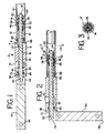
- the tube testing device 2 has a body 4 which includes an axial bore 6 extending throughout its entire length.
- the body 4 has a shoulder portion 8 and a terminal portion 10.
- the terminal portion 10 is adapted for insertion into a tube 12.
- the bore 6 is enlarged at the shoulder portion 8 of the body 4 and its function will hereinafter become apparent.
- a stem 16 is shiftably disposed within the bore 6 between the unsealed position illustrated in Figure 1 and the sealed position illustrated in Figure 2.
- the stem 16 includes a threaded first end 18 and an enlarged second end 20 which projects beyond the shoulder portion 8 of body 4.
- the stem 16 is in close tolerance relationship with the bore 6 at the terminal portion 10 of the body 4.
- a passage means 24 is formed between the bore 6 and the stem 16, at the shoulder portion 8 of the body 4.
- the stem 16 is provided with a longitudinal groove or channelway 26 which extends substantially from a point immediately below a portion of the passage means 24 to the threaded first end 18 of the stem 16 as seen in Figure 3.
- the channelway 26 provides a passage for pressurized gas to flow into the tubing.
- a handle 30 is pivotally attached to the enlarged second end 20 of the stem 16 by a pin 32.
- the handle 30 has a first end 34 and a second end 36.
- a cam washer 38 is disposed between the first end 34 of the handle 30 and the shoulder portion 8 of the body 4, which provides a camming surface for handle 30 when it is pivoted through an arc of 90° as will hereinafter become apparent.
- a counterbore 40 is defined in the left end of body 4 adjacent the cam washer 38 in communication with bore 6.
- a sealing member such as an O-ring 42 is disposed in the counter bore 40 to seal the left end of bore 6 adjacent the enlarged second end 20 of the stem 16 in fluid tight relationship.
- a wide elastomer seal 46, an actuating ring 48 and a spacer member 50 are disposed about the first end 18 of the stem 16.
- the elastomer seal 46 has a wall thickness to length ratio of approximately 1 to 3.
- the seal 46 is preferably made from chloroprene rubber which is sold under the trade name "Neoprene" by E. I. du Pont although other elastomers may be substituted if they are compatible with the test fluid and other test conditions.
- Seals which have been utilized effectively have the following sizes: (a) .89 cm (.35”)OD x .56 cm (.22")ID x .48 cm (.19") long, and (b) .74 cm (.29”)OD x .41 cm (.16")ID x .48 cm (.19”) long.
- the ring 48 and the spacer 50 encircle the stem 16 and move with it.
- the elastomer seal 46 abuts the terminal portion 10 of the body 4.
- the actuating ring 48 has a narrow end 51 and an inclined surface 52.
- a retaining ring 56 is disposed on the inclined surface 52 of the actuating ring 48 between the elastomer seal 46 and the spacer member 50.
- the spacer member 50 has a projecting portion 58 which provide the means whereby the retaining ring 56 is urged up the inclined surface 52 of the actuating ring 48 into an anchoring or locking position.
- a stop nut 62 and washer 64 are secured to the threaded first end 18 of the stem 16 so as to retain the elastomer seal 46, actuating ring 48, retaining ring 56 and spacer member 50 in the relative positions shown in Figure 1.
- a resilient stop member 66 is located on the outer periphery of the terminal portion 10 of the body 4 adjacent the shoulder portion 8. Upon insertion of the connector 2 into a tube 12, the stop member 66 engages the inner periphery of the end of tube 12 and forms a gap 68, between the tube 12 and the shoulder portion 8 of the body 4 thereby preventing the tube 12 from abutting the shoulder portion 8 of the body 4 and being damaged.
- a fluid inlet port 70 is located in the shoulder portion 8 of the body 4, and is in communication with the passage 24. This inlet port 70 is adapted to receive pressurized fluid from a pressure source (not shown).
- a pressure relief groove 72 is formed in the stem 16 at the second end 20 to provide for venting of the pressurized gas.
- the tube testing device 2 is inserted into a tube 12 for testing with the handle 30 in the unlocked, unsealed position as shown in Figure 1.
- the handle 30 is rotated counterclockwise through an arc of 90° to a locked and sealed position as shown in Figure 2.
- the stem 16 is pulled to the left, as viewed in Figure 2, thereby moving the actuating ring 48 to the left, causing the compression of the elastomer seal 46 thereby increasing its outer diameter and forcing the same into sealing engagement with the internal wall of the tube 12 to form a tight seal.
- the spacer member 50 is also moved to the left and the projecting portion 58 acts upon the retaining ring 56 to drive it up the inclined surface 52 of the actuating ring 48.
- This causes the retaining ring 56 to also engage the internal wall of the deformable tube 12 to form an internal groove and an external bead to anchor the tube testing device 2 securely in place within the tube 12.
- the relief groove 72 has portions lying on either side of the seal 42.
- the relief groove 72 is shifted entirely to the left of the O-ring 42 which seals against the escape of gas.
- a pressure tight seal is formed at the end of the tube 12 where the tube testing device 2 is attached.
- Normally a pressurized gas is used for testing the tubing but other pressurized fluid including pressurized liquids can also be used.
- Pressurized fluid is introduced into the tube testing device 2 via the inlet port 70.
- the fluid flows through the passage 24, through the longitudinal groove 26 in the stem 16 and into the tube 12 to be pressure tested.
Landscapes
- Physics & Mathematics (AREA)
- General Physics & Mathematics (AREA)
- Examining Or Testing Airtightness (AREA)
- Quick-Acting Or Multi-Walled Pipe Joints (AREA)
Claims (8)
- Röhrentestvorrichtung zum Einführen in eine offenendige Röhre (12), um ein Ende von dieser abzudichten, mit einem Körperelement (4), das eine Axialbohrung (6) und einen Endabschnitt (10) aufweist, der dazu ausgelegt ist, in das offene Ende der Röhre (12) eingeführt zu werden, einem Stab (16), welcher verschiebbar in der Bohrung (6) angeordnet ist, wobei der Stab (16) ein erstes Ende (18) hat, welches dazu ausgelegt ist, in die Röhre (12) einzutreten, und ein zweites, entgegengesetztes Ende (20) hat, welches dazu ausgelegt ist, außerhalb der Röhre (12) zu verbleiben, einer Griffeinrichtung (30), welche an dem Stab (16) festgelegt ist, um den Stab (16) zwischen einer ersten, nicht abdichtenden Position und einer zweiten, abdichtenden Position zu bewegen, einem ersten Abdichtelement (46), welches benachbart dem Endabschnitt (10) des Körperelementes (4) montiert ist, wobei das erste Abdichtelement (46) aus einem komprimierbaren elastischen Material hergestellt ist, um dessen äußeren Durchmesser zu vergrößern, wenn es lateral komprimiert wird, um an den Innenumfang der Röhre (12) anzugreifen und gegen das Entweichen von unter Druck stehendem Fluid abzudichten, einer Betätigungseinrichtung (48), welche mit dem Stab (16) verbunden ist und derart an dem ersten Abdichtelement (46) angreifen kann, daß, wenn sich der Stab (16) von der nicht abdichtenden Position in die abdichtende Position bewegt, die Betätigungseinrichtung (48) das erste Abdichtelement (46) lateral komprimiert, um dessen Außendurchmesser zu vergrößern, um das abdichtende Angreifen an der Röhre (12) zu bewirken, einem Anschluß (70), welcher in dem Körperelement (4) ausgebildet und dazu ausgelegt ist, unter Druck stehendes Fluid von einer Druckquelle zu der Axialbohrung (6) zu führen, und einem zweiten Abdichtelement (42), welches den Stab (16) an dessen zweitem Ende (20) umgibt, um gegen das Entweichen von unter Druck stehendem Fluid aus der Bohrung (6) abzudichten, wenn sich der Stab (16) in der abdichtenden Position befindet,
dadurch gekennzeichnet, daß
in dem Stab (16) an dem zweiten Ende (20) eine Druckentlastungsvertiefung (72) ausgebildet ist, die derart angeordnet ist, daß Abschnitte der Vertiefung (72) auf jeder Seite des zweiten Abdichtelementes (42) liegen, wenn der Stab (16) von der abdichtenden Position in die nicht abdichtende Position bewegt ist, wodurch ein Auslaß für unter Druck stehendes Fluid aus der Axialbohrung (6) vor dem Entfernen der getesteten Röhre (12) geschaffen wird. - Röhrentestvorrichtung nach Anspruch 1, wobei das erste Abdichtelement (46) ein Verhältnis von Wanddicke zu Länge von etwa 1 zu 3 hat.
- Röhrentestvorrichtung nach Anspruch 1 oder 2, wobei die Betätigungseinrichtung (48) einen Betätigungsring (48) aufweist, der an dem ersten Ende (18) des Stabes (16) angeordnet ist.
- Röhrentestvorrichtung nach Anspruch 3, wobei der Betätigungsring (48) ein dünnes Ende (51) und geneigte Seiten (52) hat.
- Röhrentestvorrichtung nach Anspruch 4, mit einem Abstandselement (50), welches benachbart dem Betätigungsring (48) angeordnet ist.
- Röhrentestvorrichtung nach Anspruch 5, wobei ein Haltering (56) zwischen dem ersten Abdichtelement (46) und dem Abstandselement (50) an dem Betätigungsring (48) an dessen dünnem Ende (51) angeordnet ist, derart, daß der Haltering (56) die geneigten Seiten (52) des Betätigungsringes (48) durch das Abstandselement (50) nach oben geschoben wird, wenn der Stab (16) von der nicht abdichtenden Position in die abdichtende Position bewegt wird, und an dem Innenumfang der Röhre (12) angreift, um die Röhrentestvorrichtung (2) in der Röhre (12) festzulegen.
- Röhrentestvorrichtung nach einem der vorhergehenden Ansprüche, mit einem elastischen Anschlag (66), welcher von dem Endabschnitt (10) des Körperelementes (4) an dessen Außenumfang getragen wird, wobei der Anschlag (66) dazu ausgelegt ist, an dem offenen Ende der getesteten Röhre (12) anzugreifen.
- Röhrentestvorrichtung nach einem der vorhergehenden Ansprüche, wobei das erste Abdichtelement (46) den Stab (16) bedeckt und umgibt und zwischen einem Ende des Endabschnittes (10) und der Betätigungseinrichtung (48) angeordnet ist, um hierzwischen komprimiert zu werden.
Applications Claiming Priority (2)
| Application Number | Priority Date | Filing Date | Title |
|---|---|---|---|
| US07/748,532 US5181543A (en) | 1991-08-22 | 1991-08-22 | Tube testing connector |
| US748532 | 1991-08-22 |
Publications (3)
| Publication Number | Publication Date |
|---|---|
| EP0529792A2 EP0529792A2 (de) | 1993-03-03 |
| EP0529792A3 EP0529792A3 (en) | 1993-05-19 |
| EP0529792B1 true EP0529792B1 (de) | 1996-05-22 |
Family
ID=25009851
Family Applications (1)
| Application Number | Title | Priority Date | Filing Date |
|---|---|---|---|
| EP92306522A Expired - Lifetime EP0529792B1 (de) | 1991-08-22 | 1992-07-16 | Endverschluss zum Prüfen von Rohren |
Country Status (8)
| Country | Link |
|---|---|
| US (1) | US5181543A (de) |
| EP (1) | EP0529792B1 (de) |
| JP (1) | JP2510816B2 (de) |
| KR (1) | KR930004752A (de) |
| AU (1) | AU644334B2 (de) |
| CA (1) | CA2073786A1 (de) |
| DE (1) | DE69210916T2 (de) |
| MX (1) | MX9204558A (de) |
Families Citing this family (16)
| Publication number | Priority date | Publication date | Assignee | Title |
|---|---|---|---|---|
| US5515885A (en) * | 1994-01-28 | 1996-05-14 | Lanasa; Douglas | Plug assembly |
| US5437309A (en) * | 1994-03-15 | 1995-08-01 | Timmons; Robert D. | Lockable well cap |
| US5507537A (en) * | 1994-06-02 | 1996-04-16 | Fastest, Inc. | Apparatus for gripping and sealing on the external surface of a fluid conductor |
| US5592965A (en) * | 1994-08-11 | 1997-01-14 | Dresser Industries, Inc. | Valve stop changer |
| US5799985A (en) * | 1996-08-13 | 1998-09-01 | Tuthill Corporation | Tube testing connector |
| DE19648364A1 (de) * | 1996-11-22 | 1998-05-28 | Georg Maier | Dichtprüfstopfen |
| US5740835A (en) * | 1997-04-21 | 1998-04-21 | Tuthill Corporation | Valve connector |
| DE29713797U1 (de) * | 1997-08-02 | 1998-09-03 | Weh Gmbh, Verbindungstechnik, 89257 Illertissen | Schnellanschlußkupplung, insbesondere für Glattrohre |
| US6082183A (en) * | 1998-07-22 | 2000-07-04 | Huber; Donald G. | Test assembly for fluid tight integrity of pipeline joint |
| GB0029536D0 (en) * | 2000-12-04 | 2001-01-17 | Brewis Roderick C | Pipe end fittings |
| US6502603B2 (en) * | 2001-05-16 | 2003-01-07 | John B. Lane, Jr. | Test plug handle |
| US20130032746A1 (en) | 2011-01-31 | 2013-02-07 | Kevin Dean Huber | Gasket structure for floor drain valves |
| JP2013205185A (ja) * | 2012-03-28 | 2013-10-07 | Daihatsu Motor Co Ltd | エアリーク検査装置 |
| US9416986B2 (en) | 2013-06-24 | 2016-08-16 | The Rectorseal Corporation | Valve for roof vent |
| US9010363B2 (en) | 2013-06-24 | 2015-04-21 | The Rectorseal Corporation | Drain valve |
| FR3095043B1 (fr) * | 2019-04-15 | 2021-04-30 | Gaztransport Et Technigaz | Dispositif de contrôle de l’étanchéité de composants d’étanchéité |
Family Cites Families (10)
| Publication number | Priority date | Publication date | Assignee | Title |
|---|---|---|---|---|
| US739589A (en) * | 1903-02-25 | 1903-09-22 | Garrett F Rose | Testing-plug for plumbers' use. |
| US1466450A (en) * | 1920-01-02 | 1923-08-28 | Charles James | Flue blowing and testing device |
| US2757740A (en) * | 1953-11-20 | 1956-08-07 | Donald L Bohannan | Drill stem test plug |
| US2824577A (en) * | 1955-06-27 | 1958-02-25 | Grunsky Charles | Pipe plug |
| US3542076A (en) * | 1968-03-14 | 1970-11-24 | Tuthill Pump Co | Tube tester connector |
| US3727952A (en) * | 1971-04-19 | 1973-04-17 | Tuthill Pump Co | Tube connector |
| US3738688A (en) * | 1971-05-10 | 1973-06-12 | Test Tools Inc | Quick mount fitting |
| US3779587A (en) * | 1972-08-23 | 1973-12-18 | W Racine | Tube end fitting |
| US4602500A (en) * | 1985-08-30 | 1986-07-29 | Haskel, Inc. | Apparatus for leakage testing of tubes and joints |
| AU605025B2 (en) * | 1988-10-12 | 1991-01-03 | Walter David Perry | Stop rod |
-
1991
- 1991-08-22 US US07/748,532 patent/US5181543A/en not_active Expired - Fee Related
-
1992
- 1992-07-14 CA CA002073786A patent/CA2073786A1/en not_active Abandoned
- 1992-07-16 EP EP92306522A patent/EP0529792B1/de not_active Expired - Lifetime
- 1992-07-16 DE DE69210916T patent/DE69210916T2/de not_active Expired - Fee Related
- 1992-08-06 MX MX9204558A patent/MX9204558A/es not_active IP Right Cessation
- 1992-08-10 KR KR1019920014323A patent/KR930004752A/ko not_active Withdrawn
- 1992-08-13 AU AU21021/92A patent/AU644334B2/en not_active Ceased
- 1992-08-24 JP JP4247231A patent/JP2510816B2/ja not_active Expired - Lifetime
Also Published As
| Publication number | Publication date |
|---|---|
| CA2073786A1 (en) | 1993-02-23 |
| KR930004752A (ko) | 1993-03-23 |
| AU2102192A (en) | 1993-02-25 |
| JPH05203534A (ja) | 1993-08-10 |
| MX9204558A (es) | 1993-02-01 |
| US5181543A (en) | 1993-01-26 |
| DE69210916T2 (de) | 1996-10-02 |
| AU644334B2 (en) | 1993-12-02 |
| DE69210916D1 (de) | 1996-06-27 |
| EP0529792A3 (en) | 1993-05-19 |
| EP0529792A2 (de) | 1993-03-03 |
| JP2510816B2 (ja) | 1996-06-26 |
Similar Documents
| Publication | Publication Date | Title |
|---|---|---|
| US5181543A (en) | Tube testing connector | |
| US4884830A (en) | Quick connect coupling device | |
| US4540201A (en) | Tube connector | |
| US5676174A (en) | Outer diameter pipe plug | |
| JPH0325677B2 (de) | ||
| US20220299134A1 (en) | Fitting device for making connection tube that can fine position adjustment of the tube | |
| US4068863A (en) | Pipe joint | |
| US4759572A (en) | Tube connector | |
| US5152499A (en) | Flow device body and slide-wire connector nut | |
| US3971577A (en) | Union device for flexible tubing | |
| CA1264532A (en) | Stop changer tool for in-service valve | |
| US5337598A (en) | Leak test port plug | |
| AU757937B2 (en) | Pipe testing apparatus | |
| HU218236B (hu) | Csőkötő idom | |
| NO20021496D0 (no) | Endekonnektor og rör-mot-rör konnektor for komposittkveilrör | |
| US4375297A (en) | Quick coupling device | |
| JP2829843B2 (ja) | 管の、フランジ溶接部検査装置 | |
| US3574360A (en) | Fluid-pressure-type hose clamp | |
| US5515885A (en) | Plug assembly | |
| US3709260A (en) | Apparatus for testing conduit | |
| KR0120330Y1 (ko) | 원터치 삽입식 관연결구 | |
| CA3096373C (en) | Fitting device for making connection tube that can fine position adjustment of the tube | |
| JP4421554B2 (ja) | 配管密閉治具 | |
| JPH01262433A (ja) | 水圧試験用シール治具 | |
| GB2264338A (en) | Hose connector and nipple with sealing sleeve |
Legal Events
| Date | Code | Title | Description |
|---|---|---|---|
| PUAI | Public reference made under article 153(3) epc to a published international application that has entered the european phase |
Free format text: ORIGINAL CODE: 0009012 |
|
| AK | Designated contracting states |
Kind code of ref document: A2 Designated state(s): DE GB IT |
|
| PUAL | Search report despatched |
Free format text: ORIGINAL CODE: 0009013 |
|
| AK | Designated contracting states |
Kind code of ref document: A3 Designated state(s): DE GB IT |
|
| 17P | Request for examination filed |
Effective date: 19930714 |
|
| 17Q | First examination report despatched |
Effective date: 19950131 |
|
| GRAH | Despatch of communication of intention to grant a patent |
Free format text: ORIGINAL CODE: EPIDOS IGRA |
|
| GRAA | (expected) grant |
Free format text: ORIGINAL CODE: 0009210 |
|
| AK | Designated contracting states |
Kind code of ref document: B1 Designated state(s): DE GB IT |
|
| REF | Corresponds to: |
Ref document number: 69210916 Country of ref document: DE Date of ref document: 19960627 |
|
| PGFP | Annual fee paid to national office [announced via postgrant information from national office to epo] |
Ref country code: GB Payment date: 19960708 Year of fee payment: 5 |
|
| ITF | It: translation for a ep patent filed | ||
| PGFP | Annual fee paid to national office [announced via postgrant information from national office to epo] |
Ref country code: DE Payment date: 19960722 Year of fee payment: 5 |
|
| PLBE | No opposition filed within time limit |
Free format text: ORIGINAL CODE: 0009261 |
|
| STAA | Information on the status of an ep patent application or granted ep patent |
Free format text: STATUS: NO OPPOSITION FILED WITHIN TIME LIMIT |
|
| 26N | No opposition filed | ||
| PG25 | Lapsed in a contracting state [announced via postgrant information from national office to epo] |
Ref country code: GB Free format text: LAPSE BECAUSE OF NON-PAYMENT OF DUE FEES Effective date: 19970716 |
|
| GBPC | Gb: european patent ceased through non-payment of renewal fee |
Effective date: 19970716 |
|
| PG25 | Lapsed in a contracting state [announced via postgrant information from national office to epo] |
Ref country code: DE Free format text: LAPSE BECAUSE OF NON-PAYMENT OF DUE FEES Effective date: 19980401 |
|
| PG25 | Lapsed in a contracting state [announced via postgrant information from national office to epo] |
Ref country code: IT Free format text: LAPSE BECAUSE OF NON-PAYMENT OF DUE FEES;WARNING: LAPSES OF ITALIAN PATENTS WITH EFFECTIVE DATE BEFORE 2007 MAY HAVE OCCURRED AT ANY TIME BEFORE 2007. THE CORRECT EFFECTIVE DATE MAY BE DIFFERENT FROM THE ONE RECORDED. Effective date: 20050716 |