EP0529821A1 - Endoscope - Google Patents
Endoscope Download PDFInfo
- Publication number
- EP0529821A1 EP0529821A1 EP92307045A EP92307045A EP0529821A1 EP 0529821 A1 EP0529821 A1 EP 0529821A1 EP 92307045 A EP92307045 A EP 92307045A EP 92307045 A EP92307045 A EP 92307045A EP 0529821 A1 EP0529821 A1 EP 0529821A1
- Authority
- EP
- European Patent Office
- Prior art keywords
- tip member
- guide tube
- connection
- end portion
- rear end
- Prior art date
- Legal status (The legal status is an assumption and is not a legal conclusion. Google has not performed a legal analysis and makes no representation as to the accuracy of the status listed.)
- Withdrawn
Links
- 238000003780 insertion Methods 0.000 claims description 18
- 230000037431 insertion Effects 0.000 claims description 18
- 238000004891 communication Methods 0.000 claims description 11
- 238000010276 construction Methods 0.000 description 15
- 238000005452 bending Methods 0.000 description 6
- 229920003002 synthetic resin Polymers 0.000 description 4
- 239000000057 synthetic resin Substances 0.000 description 4
- 238000005286 illumination Methods 0.000 description 3
- 230000002093 peripheral effect Effects 0.000 description 3
- 239000000853 adhesive Substances 0.000 description 2
- 230000001070 adhesive effect Effects 0.000 description 2
- 238000007689 inspection Methods 0.000 description 2
- 239000002184 metal Substances 0.000 description 2
- 239000013307 optical fiber Substances 0.000 description 2
- 230000001681 protective effect Effects 0.000 description 2
- 238000005476 soldering Methods 0.000 description 2
- 238000012986 modification Methods 0.000 description 1
- 230000004048 modification Effects 0.000 description 1
- 230000003287 optical effect Effects 0.000 description 1
- XLYOFNOQVPJJNP-UHFFFAOYSA-N water Substances O XLYOFNOQVPJJNP-UHFFFAOYSA-N 0.000 description 1
Images

Classifications
-
- A—HUMAN NECESSITIES
- A61—MEDICAL OR VETERINARY SCIENCE; HYGIENE
- A61B—DIAGNOSIS; SURGERY; IDENTIFICATION
- A61B1/00—Instruments for performing medical examinations of the interior of cavities or tubes of the body by visual or photographical inspection, e.g. endoscopes; Illuminating arrangements therefor
- A61B1/00131—Accessories for endoscopes
- A61B1/00137—End pieces at either end of the endoscope, e.g. caps, seals or forceps plugs
-
- A—HUMAN NECESSITIES
- A61—MEDICAL OR VETERINARY SCIENCE; HYGIENE
- A61B—DIAGNOSIS; SURGERY; IDENTIFICATION
- A61B1/00—Instruments for performing medical examinations of the interior of cavities or tubes of the body by visual or photographical inspection, e.g. endoscopes; Illuminating arrangements therefor
- A61B1/012—Instruments for performing medical examinations of the interior of cavities or tubes of the body by visual or photographical inspection, e.g. endoscopes; Illuminating arrangements therefor characterised by internal passages or accessories therefor
- A61B1/018—Instruments for performing medical examinations of the interior of cavities or tubes of the body by visual or photographical inspection, e.g. endoscopes; Illuminating arrangements therefor characterised by internal passages or accessories therefor for receiving instruments
Definitions
- This invention relates generally to an endoscope, and more particularly to an improved construction of connection between a tip member and a guide tube for guiding a forceps or the like.
- an endoscope comprises a body, an insertion tube extending from the body, and a rigid tip member mounted on a distal end of the insertion tube. That portion of the insertion tube which is close to the tip member and has a predetermined length serves as a bending portion. This bending portion is bent in a remotely-manipulated manner by a manipulation means provided on the body.
- the endoscope further comprises a flexible guide tube for guiding a forceps and the like.
- the guide tube is connected at its proximal end to an inlet port in the body, and extends through the body and the insertion tube, and is connected at its distal end to an outlet port in the tip member.
- connection between a tip member and a guide tube is shown in Fig. 3 of Japanese Utility Model Publication No. 3-15042. More specifically, a stepped bore is formed axially through the tip member. A front end portion of this stepped bore serves as an outlet port, and a rear end portion of the stepped bore is greater in diameter than the outlet port A front end portion of a rigid connection pipe is press-fitted in the rear end portion of the stepped bore, and is fixedly secured thereto by soldering or the like. The rear end portion of this connection pipe is projected from the rear end face of the tip member, and the guide tube is mounted on the outer periphery of this connection pipe in an expanded manner.
- the connection strength obtained is low.
- the inner diameter of the guide tube is equal to the diameter of the outlet port and the inner diameter of the connection pipe, and is relatively small.
- the corresponding portion of the guide tube is also bent to have an oval cross-sectional shape. If the inner diameter of the guide tube is small, the resistance to the passage of a forceps is increased at that portion of the guide tube having such an oval cross-sectional shape.
- FIG. 1 An improved construction between a guide tube and a tip member is shown in Fig. 1 of the above Japanese Utility Model Publication No. 3-15042. More specifically, external threads are formed on the outer periphery of the front end portion of the guide tube. On the other hand, internal threads are formed on an inner periphery of a rear end portion of a stepped bore in the tip member. By threading the front end portion of the guide tube into the rear end portion of the stepped bore in the tip member, the guide tube and the tip member are connected together. In this connection construction, a high connection strength is obtained because of the use of the threaded connection.
- the inner diameter of the guide tube is equal to the inner diameter of the outlet port, and is relatively small, the resistance to the passage of a forceps is increased at the bent portion of the guide tube, as described above.
- the inner diameter of the rear end portion of the stepped bore must also be increased, and in this connection the diameter of the tip member must also be increased, because the strength of the tip member 1 is lowered if the inner diameter of the stepped bore is increased without increasing the outer diameter of the tip member.
- an endoscope comprising:
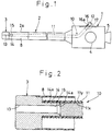
- An endoscope comprises a body 1, a flexible insertion tube 2 extending from a front end of the body 1, and a rigid tip member 3 of metal or a rigid synthetic resin mounted on a front end of the insertion tube 2.
- An inspection window and an illumination window are formed at a front end face of the tip member 3. That portion of the insertion tube 2 which is close to the tip member 3 and has a predetermined length serves as a bending portion 2a.
- the bending portion 2a is bent in a remotely-manipulated manner by a manipulation dial 4 mounted on the body 1.
- An ocular portion 5 is mounted on the body 1.
- the ocular portion 5 is connected to the inspection window of the tip member 3 via an optical system including an optical fiber, and with this arrangement a body cavity can be observed from the ocular portion 5.
- the illumination window is connected to a light source via an optical fiber bundle which passes through the insertion tube 2, the body 1 and a cable (not shown) connected to the body 1. With this arrangement, light from the light source is supplied into the body cavity through the illumination window.
- the construction of the insertion tube 2 including the bending portion 2a is well known in the art, and therefore will not be explained here, and only a protective tube 8 of a soft synthetic resin at an outermost layer of the insertion tube 2 is shown in the drawings. As shown in Fig. 2, the front end of the protective tube 8 is mounted on the outer periphery of the rear end portion of the tip member 3.
- the endoscope includes a guide means 10 for guiding a long forceps.
- the guide means 10 includes a flexible guide tube 11 of a soft synthetic resin, an inlet port 12 formed at the body 1, and an outlet port 13 formed at the tip member 3.
- the inner diameter of the guide tube 11 is greater than the inner diameter of the inlet port 12 and the inner diameter of the outlet port 13.
- the proximal end of the guide tube 11 is connected to the inlet port 12 in the body 1.
- the guide tube 11 extends through the body 1 and the insertion tube 2, and is connected at its distal end to the outlet port 13 in the tip member 3.
- the outlet port 13 is formed in and extends axially through the tip member 3.
- a tubular connection portion 14 is formed integrally with the tip member 3, and extends rearwardly from the rear end face of the tip member 3, the connection portion 14 being coaxial with the outlet port 13.
- the connection portion 14 has a communication passage 15 communicated with the outlet port 13.
- the diameter of the outlet port 13 is equal to the diameter of the communication passage 15.
- a tapered portion 14a is formed at the rear end of the communication passage 15.
- External threads 14x are formed on the outer periphery of the connection portion 14.
- the guide tube 11 has a uniform diameter throughout the length thereof.
- the guide tube 11 is in the form of a bellows having a uniform thickness throughout the length thereof, and has internal threads 11x at its inner periphery and external threads 11y at its outer periphery.
- the front or distal end portion of the guide tube 11 is connected to the outer periphery of the connection portion 14 by threadedly engaging the internal threads 11x of the guide tube 11 with the external threads 14x of the connection portion 14.
- the body 1 has a projection 16 projected outwardly therefrom, and a stepped bore 16a is formed in the projection 16.
- An outer end portion of the stepped bore 16a serves as the above-mentioned inlet port 12.
- An inner end portion of the stepped bore 16a is greater in diameter than the inlet port 12.
- the proximal end portion of the guide tube 11 is connected to the inner end portion of the stepped bore 16a through a connection tube 17 of metal or a rigid synthetic resin.
- the connection tube 17 has external threads on the outer periphery of one end portion thereof, and the proximal end portion of the guide tube 11 is threadedly connected to this externally-threaded portion of the connection tube 17.
- the other end portion of the connection tube 17 is inserted into the inner end portion of the stepped bore 16a, and is fixedly secured to the body 1 by soldering or the like.
- the guide means 10 guides the long forceps which has a flesh-collecting portion at its distal end, and a manipulation portion at its proximal end for remotely manipulating the collecting portion. More specifically, the forceps 12 is inserted from the inlet port 12 into the guide tube 11, and is guided by the guide tube 11, so that the distal end of the forceps 12 is projected from the outlet port 13 to face a body cavity. A piece of flesh on the inner wall of the body cavity is collected by remotely manipulating the collecting portion of the forceps.
- connection between the guide tube 11 and the tip member 3 since the distal end portion of the guide tube 11 is threadedly connected to the outer periphery of the connection portion 14, the strength of connection between the two can be enhanced.
- the inner diameter of the guide tube 11 is larger than the diameter of the outlet port 13, and therefore for example, when the bending portion 2a is bent, so that the corresponding portion of the guide tube 11 is deformed into an oval cross-sectional shape, this deformed portion will not prevent the passage of the forceps, and the resistance to the passage of the forceps is small.
- the diameter of the output port 13 can be kept small, and the outer diameter of the tip member 13 does not need to be increased. Incidentally, if the outer diameter of the tip member 3 is increased, this gives a greater pain to the patient.
- the collecting portion at the distal end of the forceps is guided by the tapered portion 14a of the connection portion 14, and therefore can be smoothly introduced from the guide tube 11 into the communication passage 15 of a smaller diameter.
- FIGs. 3 to 5 show other preferred embodiments of the present invention, respectively. Those portions of these embodiments corresponding to those of the preceding embodiment are designated by identical reference numerals, respectively, and detailed explanation thereof will be omitted.
- a mounting hole 103a in the form of a threaded hole is formed axially through a tip member 103.
- connection pipe or tube 114 separate from the tip member 103.
- the connection pipe 114 has a through hole (internal bore) 114a.
- a front end portion of the through hole 114a serves as an outlet port 113, and a rear end portion thereof serves as a communication passage 115.
- a tapered portion 114b is formed at the rear end of the through hole 114a.
- the connection pipe 114 has a larger-diameter rear portion (connection portion) 114m, and a smaller-diameter front portion 114n.
- External threads 114x are formed on the outer periphery of the larger-diameter portion 114m, and external threads 114y are formed on the outer periphery of the smaller-diameter portion 114n.
- the smaller-diameter portion 114n of the connection pipe 114 is threaded into the mounting hole 103a of the tip member 103 until the front end face of the larger-diameter portion 114m is brought into contact with the rear end face of the tip member 103. By doing so, the connection pipe 114 is connected to the tip member 103.
- a guide tube 111 used in this embodiment has a uniform diameter throughout a length thereof, and has internal threads 111x on its inner periphery, and has a cylindrical outer peripheral surface. The guide tube 111 is threadedly connected to the outer periphery of the larger-diameter portion 114m of the connection pipe 114.
- a mounting hole 203a is formed axially through a tip member 203.
- a connection pipe 214 separate from the tip member 203 has a through hole (internal bore) 214a, and also has a larger-diameter rear portion (connection portion) 214m, a smaller-diameter front portion 214n, and a flange 214f between the two portions 214m and 214n.
- a front end portion of the through hole 214a serves as an outlet port 213, and a rear end portion thereof serves as a communication passage 215.
- a tapered portion 214b is formed at the rear end of the through hole 214a.
- the outer diameter of the smaller-diameter portion 214n is equal to the inner diameter of the mounting hole 203a.
- the smaller-diameter portion 214n of the connection pipe 214 is inserted into the mounting hole 203a in the tip member 203, with the flange 214f held against the rear end face of the tip member 203, and in this condition bolts 220 are threaded into the rear end face of the tip member 203 through the flange 214f, thereby fixedly securing the connection pipe 214 to the tip member 203.
- External threads 214x are formed on the outer periphery of the larger-diameter portion 214m.
- a guide tube 111 is threadedly connected to the outer periphery of the larger-diameter portion 214m.
- a mounting hole 303a in the form of a threaded hole is formed axially through a tip member 303.
- a connection pipe 314 separate from the tip member 303 is in the form of a threaded pipe whose outer diameter is uniform throughout the length thereof, the threaded pipe having external threads 314x over the entire outer peripheral surface thereof.
- the connection pipe 314 is fixedly secured to the tip member 303 by threading the front end portion of the connection pipe 314 into the mounting hole 303a.
- a guide tube 111 is threadedly connected to the rear end portion (connection portion) of the connection pipe 314 projected from the rear end face of the tip member 303.
- a front end portion of a through hole 314a in the connection pipe 314 serves as an outlet port 313, and a rear end portion of thereof serves as a communication passage 315.
- a tapered portion 314b is formed at rear end of the through hole 314a.
- the present invention is not limited to the above embodiments, and suitable modifications can be made without departing the scope of the invention.
- the present invention can be applied to a construction of connection between a tip member and a guide tube for guiding an elongate member having a brush at its distal end, or for guiding the air, water or the like.
- the outlet port may be open to the outer peripheral surface of the tip member.
- Internal threads may be formed only on the inner periphery of the front end portion of the guide tube.
- an adhesive may be used for connecting the connection pipe and the tip member together and for connecting the guide tube and the connection portion together.
Landscapes
- Health & Medical Sciences (AREA)
- Life Sciences & Earth Sciences (AREA)
- Surgery (AREA)
- Biomedical Technology (AREA)
- Medical Informatics (AREA)
- Optics & Photonics (AREA)
- Pathology (AREA)
- Radiology & Medical Imaging (AREA)
- Biophysics (AREA)
- Engineering & Computer Science (AREA)
- Physics & Mathematics (AREA)
- Heart & Thoracic Surgery (AREA)
- Nuclear Medicine, Radiotherapy & Molecular Imaging (AREA)
- Molecular Biology (AREA)
- Animal Behavior & Ethology (AREA)
- General Health & Medical Sciences (AREA)
- Public Health (AREA)
- Veterinary Medicine (AREA)
- Endoscopes (AREA)
- Instruments For Viewing The Inside Of Hollow Bodies (AREA)
Applications Claiming Priority (2)
| Application Number | Priority Date | Filing Date | Title |
|---|---|---|---|
| JP237368/91 | 1991-08-23 | ||
| JP3237368A JPH0549593A (ja) | 1991-08-23 | 1991-08-23 | 内視鏡における先端構成部とチヤンネルチユーブとの接続構造 |
Publications (1)
| Publication Number | Publication Date |
|---|---|
| EP0529821A1 true EP0529821A1 (fr) | 1993-03-03 |
Family
ID=17014357
Family Applications (1)
| Application Number | Title | Priority Date | Filing Date |
|---|---|---|---|
| EP92307045A Withdrawn EP0529821A1 (fr) | 1991-08-23 | 1992-08-03 | Endoscope |
Country Status (3)
| Country | Link |
|---|---|
| US (1) | US5261391A (fr) |
| EP (1) | EP0529821A1 (fr) |
| JP (1) | JPH0549593A (fr) |
Families Citing this family (32)
| Publication number | Priority date | Publication date | Assignee | Title |
|---|---|---|---|---|
| JP4619181B2 (ja) * | 2005-04-04 | 2011-01-26 | Hoya株式会社 | 内視鏡の自動進退装置 |
| US20070066870A1 (en) * | 2005-09-22 | 2007-03-22 | Katsuaki Ohashi | Hood for endoscope |
| US7815564B2 (en) * | 2006-02-21 | 2010-10-19 | Boston Scientific Scimed, Inc. | Positioning system for manipulating a channel within a medical device |
| JP5144901B2 (ja) * | 2006-06-06 | 2013-02-13 | Hoya株式会社 | 内視鏡の先端部 |
| US9254123B2 (en) | 2009-04-29 | 2016-02-09 | Hansen Medical, Inc. | Flexible and steerable elongate instruments with shape control and support elements |
| US8827948B2 (en) | 2010-09-17 | 2014-09-09 | Hansen Medical, Inc. | Steerable catheters |
| US20130030363A1 (en) | 2011-07-29 | 2013-01-31 | Hansen Medical, Inc. | Systems and methods utilizing shape sensing fibers |
| CN103260498B (zh) * | 2011-09-05 | 2016-01-06 | 奥林巴斯株式会社 | 内窥镜 |
| US10149720B2 (en) | 2013-03-08 | 2018-12-11 | Auris Health, Inc. | Method, apparatus, and a system for facilitating bending of an instrument in a surgical or medical robotic environment |
| US10376672B2 (en) | 2013-03-15 | 2019-08-13 | Auris Health, Inc. | Catheter insertion system and method of fabrication |
| CN105939647B (zh) | 2013-10-24 | 2020-01-21 | 奥瑞斯健康公司 | 机器人辅助腔内外科手术系统及相关方法 |
| US9744335B2 (en) | 2014-07-01 | 2017-08-29 | Auris Surgical Robotics, Inc. | Apparatuses and methods for monitoring tendons of steerable catheters |
| US10792464B2 (en) | 2014-07-01 | 2020-10-06 | Auris Health, Inc. | Tool and method for using surgical endoscope with spiral lumens |
| US9561083B2 (en) | 2014-07-01 | 2017-02-07 | Auris Surgical Robotics, Inc. | Articulating flexible endoscopic tool with roll capabilities |
| US11819636B2 (en) | 2015-03-30 | 2023-11-21 | Auris Health, Inc. | Endoscope pull wire electrical circuit |
| US20160367120A1 (en) * | 2015-06-19 | 2016-12-22 | Children's Medical Center Corporation | Optically Guided Surgical Devices |
| BR112018016496A2 (pt) | 2016-02-12 | 2018-12-26 | Childrens Medical Center | porta-instrumento com sistema de formação de imagem integrado |
| US10463439B2 (en) | 2016-08-26 | 2019-11-05 | Auris Health, Inc. | Steerable catheter with shaft load distributions |
| CN110769736B (zh) | 2017-05-17 | 2023-01-13 | 奥瑞斯健康公司 | 可更换工作通道 |
| US11284788B2 (en) | 2018-03-09 | 2022-03-29 | The Children's Medical Center Corporation | Instrument port with fluid flush system |
| US11324555B2 (en) * | 2018-03-09 | 2022-05-10 | The Children's Medical Center Corporation | Instrument port including optical bulb secured to port body |
| US11547276B2 (en) | 2018-03-09 | 2023-01-10 | The Children's Medical Center Corporation | Optical bulb for surgical instrument port |
| US11213316B2 (en) | 2018-03-09 | 2022-01-04 | The Children's Medical Center Corporation | Gasket with multi-leaflet valve for surgical port apparatus |
| WO2019190657A1 (fr) | 2018-03-28 | 2019-10-03 | Auris Health, Inc. | Instruments médicaux ayant des profils variables de rigidité à la flexion |
| CN112399815B (zh) * | 2018-07-19 | 2024-09-13 | 富士胶片株式会社 | 内窥镜辅助器具及内窥镜 |
| WO2020033318A1 (fr) | 2018-08-07 | 2020-02-13 | Auris Health, Inc. | Combinaison de détection de forme basée sur des contraintes avec commande de cathéter |
| WO2020068853A2 (fr) | 2018-09-26 | 2020-04-02 | Auris Health, Inc. | Articulation d'instruments médicaux |
| CN113286543A (zh) | 2018-12-28 | 2021-08-20 | 奥瑞斯健康公司 | 具有可关节运动区段的医疗器械 |
| US11617627B2 (en) | 2019-03-29 | 2023-04-04 | Auris Health, Inc. | Systems and methods for optical strain sensing in medical instruments |
| CN114554930A (zh) | 2019-08-15 | 2022-05-27 | 奥瑞斯健康公司 | 具有多个弯曲节段的医疗装置 |
| EP4084717A4 (fr) | 2019-12-31 | 2024-02-14 | Auris Health, Inc. | Système de poulie dynamique |
| WO2021176709A1 (fr) * | 2020-03-06 | 2021-09-10 | オリンパス株式会社 | Partie raccordement d'élément tubulaire pour endoscope et endoscope |
Citations (3)
| Publication number | Priority date | Publication date | Assignee | Title |
|---|---|---|---|---|
| DE3621374A1 (de) * | 1985-06-28 | 1987-01-08 | Olympus Optical Co | Behandlungsinstrument eines endoskopes |
| US4875468A (en) * | 1988-12-23 | 1989-10-24 | Welch Allyn, Inc. | Elastomer-ePTFE biopsy channel |
| US4967732A (en) * | 1989-05-01 | 1990-11-06 | Kabushiki Kaisha Machida Seisakusho | Endoscope |
Family Cites Families (7)
| Publication number | Priority date | Publication date | Assignee | Title |
|---|---|---|---|---|
| JPS576241Y2 (fr) * | 1973-08-31 | 1982-02-05 | ||
| JPS5689231A (en) * | 1979-12-21 | 1981-07-20 | Olympus Optical Co | Endoscope |
| DE3111412A1 (de) * | 1981-03-24 | 1982-11-18 | Storz, Karl, 7200 Tuttlingen | Endoskop mit einem bilduebertragendem flexiblem element |
| JPH0644105B2 (ja) * | 1985-01-14 | 1994-06-08 | オリンパス光学工業株式会社 | 内視鏡 |
| US4771766A (en) * | 1986-07-08 | 1988-09-20 | Kabushiki Kaisha Machida Seisakusho | Guide tube assembly of endoscope |
| US4928699A (en) * | 1987-05-18 | 1990-05-29 | Olympus Optical Co., Ltd. | Ultrasonic diagnosis device |
| JPH065761Y2 (ja) * | 1988-04-25 | 1994-02-16 | 旭光学工業株式会社 | 内視鏡 |
-
1991
- 1991-08-23 JP JP3237368A patent/JPH0549593A/ja active Pending
-
1992
- 1992-07-31 US US07/922,779 patent/US5261391A/en not_active Expired - Fee Related
- 1992-08-03 EP EP92307045A patent/EP0529821A1/fr not_active Withdrawn
Patent Citations (3)
| Publication number | Priority date | Publication date | Assignee | Title |
|---|---|---|---|---|
| DE3621374A1 (de) * | 1985-06-28 | 1987-01-08 | Olympus Optical Co | Behandlungsinstrument eines endoskopes |
| US4875468A (en) * | 1988-12-23 | 1989-10-24 | Welch Allyn, Inc. | Elastomer-ePTFE biopsy channel |
| US4967732A (en) * | 1989-05-01 | 1990-11-06 | Kabushiki Kaisha Machida Seisakusho | Endoscope |
Also Published As
| Publication number | Publication date |
|---|---|
| JPH0549593A (ja) | 1993-03-02 |
| US5261391A (en) | 1993-11-16 |
Similar Documents
| Publication | Publication Date | Title |
|---|---|---|
| US5261391A (en) | Threaded flexible guide tube for endoscope | |
| US4971035A (en) | Insert part of endoscope | |
| US6471641B2 (en) | Joint construction for connecting an angle section to a flexible body section of endoscopic insertion instrument | |
| US11471031B2 (en) | Articulated tip part for an endoscope | |
| EP0812565B1 (fr) | Unité d'endoscope | |
| US6878108B2 (en) | Insertion unit for endoscope | |
| CN108463154B (zh) | 内窥镜 | |
| JP4017734B2 (ja) | 内視鏡の挿入部 | |
| JP3120869B2 (ja) | 内視鏡の先端部 | |
| JP2556002Y2 (ja) | 内視鏡 | |
| JP3590199B2 (ja) | 内視鏡 | |
| JP3499987B2 (ja) | ベビースコープの挿入部可撓管 | |
| JP2000051144A (ja) | 内視鏡 | |
| JPH11244223A (ja) | 内視鏡の処置具挿通チャンネル | |
| JP3309568B2 (ja) | 内視鏡の処置具挿通チャンネル固定機構 | |
| JP4021187B2 (ja) | 内視鏡の先端部 | |
| JP4021041B2 (ja) | 内視鏡の挿入部 | |
| JPH0475005B2 (fr) | ||
| JPH01287523A (ja) | 内視鏡挿入補助具 | |
| JPS61259636A (ja) | 内視鏡湾曲操作装置 | |
| JP4017735B2 (ja) | 内視鏡の挿入部 | |
| JPH0630162Y2 (ja) | 内視鏡の先端部 | |
| JPH0632082Y2 (ja) | 内視鏡 | |
| JP3174134B2 (ja) | 内視鏡 | |
| JPS6348241Y2 (fr) |
Legal Events
| Date | Code | Title | Description |
|---|---|---|---|
| PUAI | Public reference made under article 153(3) epc to a published international application that has entered the european phase |
Free format text: ORIGINAL CODE: 0009012 |
|
| AK | Designated contracting states |
Kind code of ref document: A1 Designated state(s): DE FR GB |
|
| 17P | Request for examination filed |
Effective date: 19930726 |
|
| 17Q | First examination report despatched |
Effective date: 19931026 |
|
| STAA | Information on the status of an ep patent application or granted ep patent |
Free format text: STATUS: THE APPLICATION IS DEEMED TO BE WITHDRAWN |
|
| 18D | Application deemed to be withdrawn |
Effective date: 19950119 |