EP0530102B1 - Behälter mit Flüssigkeitsstandmessvorrichtung - Google Patents
Behälter mit Flüssigkeitsstandmessvorrichtung Download PDFInfo
- Publication number
- EP0530102B1 EP0530102B1 EP92402346A EP92402346A EP0530102B1 EP 0530102 B1 EP0530102 B1 EP 0530102B1 EP 92402346 A EP92402346 A EP 92402346A EP 92402346 A EP92402346 A EP 92402346A EP 0530102 B1 EP0530102 B1 EP 0530102B1
- Authority
- EP
- European Patent Office
- Prior art keywords
- casing
- wall portion
- container according
- container
- main wall
- Prior art date
- Legal status (The legal status is an assumption and is not a legal conclusion. Google has not performed a legal analysis and makes no representation as to the accuracy of the status listed.)
- Expired - Lifetime
Links
Images
Classifications
-
- G—PHYSICS
- G01—MEASURING; TESTING
- G01F—MEASURING VOLUME, VOLUME FLOW, MASS FLOW OR LIQUID LEVEL; METERING BY VOLUME
- G01F23/00—Indicating or measuring liquid level or level of fluent solid material, e.g. indicating in terms of volume or indicating by means of an alarm
- G01F23/22—Indicating or measuring liquid level or level of fluent solid material, e.g. indicating in terms of volume or indicating by means of an alarm by measuring physical variables, other than linear dimensions, pressure or weight, dependent on the level to be measured, e.g. by difference of heat transfer of steam or water
- G01F23/26—Indicating or measuring liquid level or level of fluent solid material, e.g. indicating in terms of volume or indicating by means of an alarm by measuring physical variables, other than linear dimensions, pressure or weight, dependent on the level to be measured, e.g. by difference of heat transfer of steam or water by measuring variations of capacity or inductance of capacitors or inductors arising from the presence of liquid or fluent solid material in the electric or electromagnetic fields
- G01F23/263—Indicating or measuring liquid level or level of fluent solid material, e.g. indicating in terms of volume or indicating by means of an alarm by measuring physical variables, other than linear dimensions, pressure or weight, dependent on the level to be measured, e.g. by difference of heat transfer of steam or water by measuring variations of capacity or inductance of capacitors or inductors arising from the presence of liquid or fluent solid material in the electric or electromagnetic fields by measuring variations in capacitance of capacitors
- G01F23/268—Indicating or measuring liquid level or level of fluent solid material, e.g. indicating in terms of volume or indicating by means of an alarm by measuring physical variables, other than linear dimensions, pressure or weight, dependent on the level to be measured, e.g. by difference of heat transfer of steam or water by measuring variations of capacity or inductance of capacitors or inductors arising from the presence of liquid or fluent solid material in the electric or electromagnetic fields by measuring variations in capacitance of capacitors mounting arrangements of probes
-
- Y—GENERAL TAGGING OF NEW TECHNOLOGICAL DEVELOPMENTS; GENERAL TAGGING OF CROSS-SECTIONAL TECHNOLOGIES SPANNING OVER SEVERAL SECTIONS OF THE IPC; TECHNICAL SUBJECTS COVERED BY FORMER USPC CROSS-REFERENCE ART COLLECTIONS [XRACs] AND DIGESTS
- Y10—TECHNICAL SUBJECTS COVERED BY FORMER USPC
- Y10S—TECHNICAL SUBJECTS COVERED BY FORMER USPC CROSS-REFERENCE ART COLLECTIONS [XRACs] AND DIGESTS
- Y10S220/00—Receptacles
- Y10S220/901—Liquified gas content, cryogenic
Definitions
- the present invention relates to a container, of the type comprising at least one envelope defining an interior volume, the envelope comprising a main part for containing at least one liquid, delimited peripherally by a main wall portion, and an end part forming a access passage to the interior volume and of transverse dimensions smaller than those of the main part, removable closure means for closing the access passage, and capacitive type level detection means providing a signal representative of a level liquid in the main part of the envelope.
- the present invention relates to any type of liquid container with an electrical conductivity coefficient different from that of the gaseous sky overhanging the liquid in the envelope of the container and requiring access to the interior volume of the container, and more particularly cryogenic containers, in particular, although not exclusively, for the storage of biological products in a cryogenic liquid such as liquid nitrogen.
- the object of the present invention is to provide a container fitted with level detector means in a simple and reliable arrangement, with low manufacturing and assembly costs, permanently allowing free access to the interior volume without interfering with the products which must be there. willing.
- the main wall portion is substantially cylindrical
- the detector means comprise at least one electrode mounted in the vicinity of the main wall portion, the electrode consisting of an elongated blade extending parallel to a generatrix of the main wall portion and having, in cross section, an arcuate shape substantially concentric with the adjacent main wall portion.
- the envelope is metallic and constitutes one of the electrodes of the detector means.
- the detector means are permanently installed in the factory and are located in a "neutral" zone of the interior volume of the envelope, offset from the passage or access neck, while not occupying it. only a minimal volume, in no way interfering with the products to be placed in the envelope and without obstructing or even clogging up the access passage.
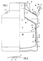
- FIG. 1 shows a transportable cryogenic container conventionally comprising an outer envelope 1 and an inner envelope 2 of revolution, the space between the two envelopes 1 and 2 being placed under vacuum and / or filled with thermal insulation.
- the casing 2 typically made of metal such as steel or aluminum, has a lower main part delimited peripherally by a cylindrical main wall portion 3 and defining an internal storage volume 4, the internal envelope 2 comprising, at its upper end, a neck portion of reduced diameter 5 to which a neck portion is connected end 6 of the outer casing 1 and defining a passage 7 for access to the interior volume 4 closable by a removable closure cap 8.
- the electrodes are connected to conductive wires 12, 12 ′ running along the wall of the envelope 3 in a grommet tube 13 kept pressed against the wall by a flange 19 and extending along the wall of the neck 5 then, falling back on the outer wall of the outer casing 1, the conductors 12 and 12 ′ extending out of the cap 8, to a reading box 14 fixed on the outer casing 1, for example by means of the connector 15 for evacuating the space between the two envelopes 1 and 2 and forming the electrical connection between the electronic circuits of the housing 14 and of the interior envelope 2.
- the reading unit 14 powered by an electric battery, comprises electronic means for digital processing of the signal supplied by the electrodes 12 and 12 ′ as a function of the level of liquid 160 contained in the internal envelope 3, this level being displayed on a level indicator 16.
- the housing 14 further comprises an audible indicator 17 emitting an audible signal when the liquid level in the envelope 2 reaches a determined minimum threshold and advantageously an interfacing connector 17 connectable to a box of a container filling system, operated via the neck 7, so as to control the filling device as a function of the level read in real time by the electrodes 9, 9 ′ via the box 14.
- the electrodes 9 and 9 ′ advantageously have, in cross section, the form of arcs of a circle concentric with the wall 3 of the envelope 2.
- cryogenic containers for biological products also applied "cryopreservatives"
- the electrodes 9 and 9 ′ will be arranged in one of the dead zones between two adjacent storage baskets received in the main part of the envelope 2.
- the conducting wires 12 and 12 ′ can pass through the envelopes 2 and 1 in a sealed manner, for example in a grommet tube formed in the lower part of the tank, the reading box 14 being advantageously arranged also at the base of the tank and being connected to a central gas distribution management station, in particular for remote monitoring.
Landscapes
- Physics & Mathematics (AREA)
- Engineering & Computer Science (AREA)
- Power Engineering (AREA)
- Electromagnetism (AREA)
- Thermal Sciences (AREA)
- Fluid Mechanics (AREA)
- General Physics & Mathematics (AREA)
- Filling Or Discharging Of Gas Storage Vessels (AREA)
- Measurement Of Levels Of Liquids Or Fluent Solid Materials (AREA)
- Level Indicators Using A Float (AREA)
- Containers, Films, And Cooling For Superconductive Devices (AREA)
Claims (8)
- Behälter, mit mindestens einem ein Innenvolumen (4) umschließenden Mantel (2), der einen an seinem Rande von einem Hauptwandabschnitt (3) begrenzten Hauptteil zur Aufnahme mindestens einer Flüssigkeit (160) und einen Endteil (5) umfaßt, der einen Zugangsdurchtritt (7) zu dem Innenvolumen (4) bildet und Abmessungen in Querrichtung hat, die kleiner als diejenigen des Hauptteils sind, einer abnehmbaren Verschlußeinrichtung (8) zum Verschließen des Zugangsdurchtritts (7), und Füllstanderfassungseinrichtungen (9, 9′) kapazitiver Bauart, die ein für einen Flüssigkeitsstand in dem Hauptteil des Mantels repräsentatives Signal liefern, dadurch gekennzeichnet, daß der Hauptwandabschnitt (3) zylindrisch ist und daß die Erfassungseinrichtungen mindestens eine in der Nähe des Hauptwandabschnitts montierte Elektrode (9, 9′) aufweisen, wobei die Elektrode (9, 9′) aus einer länglichen Lamelle besteht, die sich parallel zu einer Erzeugenden des Hauptwandabschnitts erstreckt und im Querschnitt die Form eines Kreisbogens hat, der zu dem danebenliegenden Hauptwandabschnitt (3) konzentrisch ist.
- Behälter nach Anspruch 1, dadurch gekennzeichnet, daß der Mantel (2) aus leitendem Metall besteht und eine Elektrode der Erfassungseinrichtungen (9, 9′) bildet.
- Behälter nach Anspruch 1 oder 2, dadurch gekennzeichnet, daß er zwei voneinander und von dem Hauptwandabschnitt beabstandete und zu letzterem im wesentlichen konzentrische parallele Elektroden (9, 9′) aufweist.
- Behälter nach einem der Ansprüche 1 bis 3, dadurch gekennzeichnet, daß er ein an dem Behälter montiertes Gehäuse (14) zur Verarbeitung des Signals der Erfassungseinrichtungen (9, 9′) aufweist.
- Behälter nach Anspruch 4, dadurch gekennzeichnet, daß das Gehäuse (14) mit den Erfassungseinrichtungen (9, 9′) über mindestens einen Leitungsdraht (12, 12′) verbunden ist, der durch den Zugangsdurchtritt (7) verläuft und sich außerhalb der Verschlußeinrichtung (8) erstreckt.
- Behälter nach Anspruch 4 oder 5, dadurch gekennzeichnet, daß das Gehäuse (14) eine visuelle Anzeigevorrichtung (16) für den Füllstand der Flüssigkeit (160) in dem Mantel aufweist.
- Behälter nach einem der vorhergehenden Ansprüche, dadurch gekennzeichnet, daß er einen den Mantel (2), welcher das Innenvolumen (4) festlegt, umgebenden Außenmantel (1) aufweist.
- Verwendung eines Behälters nach Anspruch 7 zur Lagerung biologischer Produkte in einer kryogenen Flüssigkeit.
Applications Claiming Priority (2)
| Application Number | Priority Date | Filing Date | Title |
|---|---|---|---|
| FR9110782A FR2680767A1 (fr) | 1991-08-30 | 1991-08-30 | Conteneur comportant des moyens detecteurs de niveau de liquide dans le conteneur. |
| FR9110782 | 1991-08-30 |
Publications (2)
| Publication Number | Publication Date |
|---|---|
| EP0530102A1 EP0530102A1 (de) | 1993-03-03 |
| EP0530102B1 true EP0530102B1 (de) | 1995-07-12 |
Family
ID=9416512
Family Applications (1)
| Application Number | Title | Priority Date | Filing Date |
|---|---|---|---|
| EP92402346A Expired - Lifetime EP0530102B1 (de) | 1991-08-30 | 1992-08-27 | Behälter mit Flüssigkeitsstandmessvorrichtung |
Country Status (7)
| Country | Link |
|---|---|
| US (1) | US5230439A (de) |
| EP (1) | EP0530102B1 (de) |
| AT (1) | ATE125039T1 (de) |
| DE (1) | DE69203413T2 (de) |
| ES (1) | ES2074847T3 (de) |
| FR (1) | FR2680767A1 (de) |
| RU (1) | RU2065393C1 (de) |
Families Citing this family (18)
| Publication number | Priority date | Publication date | Assignee | Title |
|---|---|---|---|---|
| US6460742B1 (en) * | 1989-02-14 | 2002-10-08 | L'air Liquide Societe Anonyme Pour L'etude Et L'exploitation Des Procedes Georges Claude | Process for reducing fume emissions during molten metal transfer |
| US5567887A (en) * | 1994-03-10 | 1996-10-22 | Texas Instruments Incorporated | Anhydrous ammonia gas sampler and concentration system |
| US5745377A (en) * | 1995-03-20 | 1998-04-28 | Figgie International Inc. | Method and apparatus for determining quantity of liquid in a container and/or lack of motion thereof |
| US5790422A (en) * | 1995-03-20 | 1998-08-04 | Figgie International Inc. | Method and apparatus for determining the quantity of a liquid in a container independent of its spatial orientation |
| US5726908A (en) * | 1995-03-20 | 1998-03-10 | Figgie International Inc. | Liquid quantity sensor and method |
| US20100281886A1 (en) * | 2006-09-11 | 2010-11-11 | Core Dynamics Limited | Systems, devices and methods for freezing and thawing biological materials |
| US7736328B2 (en) | 2007-07-05 | 2010-06-15 | Baxter International Inc. | Dialysis system having supply container autoconnection |
| US8496609B2 (en) | 2007-07-05 | 2013-07-30 | Baxter International Inc. | Fluid delivery system with spiked cassette |
| US7808246B2 (en) * | 2007-07-05 | 2010-10-05 | Baxter International Inc. | Apparatus and method for verifying a seal between multiple chambers |
| US8105266B2 (en) * | 2007-07-05 | 2012-01-31 | Baxter International Inc. | Mobile dialysis system having supply container detection |
| US7955295B2 (en) | 2007-07-05 | 2011-06-07 | Baxter International Inc. | Fluid delivery system with autoconnect features |
| US8152116B2 (en) * | 2008-02-27 | 2012-04-10 | Baxter International Inc. | Dialysate bag seal breakage sensor incorporated in dialysate bag management |
| US8099967B2 (en) * | 2008-04-10 | 2012-01-24 | Yu Jia | Portable rack carrier device and the method of use |
| DE102010010749B4 (de) * | 2010-03-09 | 2016-12-22 | Wacker Neuson Produktion GmbH & Co. KG | Antriebssystem mit Vorrichtung zur Unterbrechung des Betriebs bei drohendem Betriebsstoffmangel sowie Arbeitsgerät und Verfahren |
| US10647484B2 (en) * | 2014-12-18 | 2020-05-12 | Waterio Ltd. | Device for reminding and measuring material level inside a material container |
| WO2020171728A1 (ru) | 2019-02-21 | 2020-08-27 | Общество С Ограниченной Ответственностью "Омником Технологии" | Емкостной датчик уровня границы раздела сред |
| EP3957898A1 (de) * | 2020-08-20 | 2022-02-23 | Hexagon Ragasco AS | System und verfahren zur digitalen überwachung eines druckbehälters |
| EP3957899A1 (de) * | 2020-08-20 | 2022-02-23 | Hexagon Ragasco AS | Digitale überwachung eines zusammengesetzten druckbehälters |
Family Cites Families (10)
| Publication number | Priority date | Publication date | Assignee | Title |
|---|---|---|---|---|
| FR1162975A (fr) * | 1955-04-06 | 1958-09-19 | Bendix Aviat Corp | Perfectionnements aux appareils électriques destinés à effectuer des mesures sur des fluides à basse température |
| GB792484A (en) * | 1955-12-08 | 1958-03-26 | Aro Equipment Corp | Improvements in or relating to liquid level indicator |
| FR1188282A (fr) * | 1956-12-14 | 1959-09-21 | British Oxygen Co Ltd | Dispositif d'indication du niveau de liquides |
| US3167695A (en) * | 1961-10-20 | 1965-01-26 | John C Bronson | Liquid level capacitance probe |
| US3119238A (en) * | 1963-02-18 | 1964-01-28 | William H Chamberlain | Cryogenic dewar |
| US4332167A (en) * | 1975-11-28 | 1982-06-01 | Drexelbrook Controls, Inc. | Method of making an RF admittance measuring probe and product thereof |
| JPS5619723U (de) * | 1979-07-23 | 1981-02-21 | ||
| FR2529293A1 (fr) * | 1982-06-29 | 1983-12-30 | Air Liquide | Procede de fabrication d'un recipient a forte isolation thermique |
| US4674289A (en) * | 1985-06-26 | 1987-06-23 | Andonian Martin D | Cryogenic liquid container |
| DE3621425A1 (de) * | 1986-06-25 | 1988-01-14 | Messer Griesheim Gmbh | Vorrichtung zur erzeugung eines kalten behandlungsgases fuer die kryotherapie |
-
1991
- 1991-08-30 FR FR9110782A patent/FR2680767A1/fr active Granted
-
1992
- 1992-08-18 US US07/931,332 patent/US5230439A/en not_active Expired - Fee Related
- 1992-08-27 AT AT92402346T patent/ATE125039T1/de not_active IP Right Cessation
- 1992-08-27 ES ES92402346T patent/ES2074847T3/es not_active Expired - Lifetime
- 1992-08-27 EP EP92402346A patent/EP0530102B1/de not_active Expired - Lifetime
- 1992-08-27 DE DE69203413T patent/DE69203413T2/de not_active Expired - Fee Related
- 1992-08-28 RU SU925052658A patent/RU2065393C1/ru active
Also Published As
| Publication number | Publication date |
|---|---|
| ES2074847T3 (es) | 1995-09-16 |
| DE69203413D1 (de) | 1995-08-17 |
| US5230439A (en) | 1993-07-27 |
| DE69203413T2 (de) | 1995-12-21 |
| ATE125039T1 (de) | 1995-07-15 |
| RU2065393C1 (ru) | 1996-08-20 |
| FR2680767B1 (de) | 1994-12-23 |
| EP0530102A1 (de) | 1993-03-03 |
| FR2680767A1 (fr) | 1993-03-05 |
Similar Documents
| Publication | Publication Date | Title |
|---|---|---|
| EP0530102A1 (de) | Behälter mit Flüssigkeitsstandmessvorrichtung | |
| BE1008563A3 (fr) | Dispositif de controle. | |
| ES2578054T3 (es) | Cierre | |
| US8367935B2 (en) | Electrical power connection device | |
| EP1703611B1 (de) | Elektrische Durchführung für supraleitendes Element | |
| EP1387799B1 (de) | Vorrichtung zum speichern und transportieren von pulverförmigen oder flüssigen produkten | |
| FR2574589A1 (fr) | Dispositif de mise en court-circuit exterieur de faible encombrement | |
| KR102904181B1 (ko) | 충전재를 위한 플라스틱 운반 및 저장 용기 | |
| FR2953977A1 (fr) | Dispositif de raccordement electrique d'une barre appartenant a un jeu de barres a une traversee electrique appartenant a l'enveloppe isolante d'un appareil electrique de coupure | |
| US20040231730A1 (en) | Earthing structure of fuel tank | |
| FR2527382A1 (fr) | Fusible pour circuit electrique comportant un indicateur de fusion monte lateralement | |
| US20030196923A1 (en) | IBC for combustible products | |
| WO2015193619A1 (fr) | Systeme electrique avec blindage | |
| CA2241257A1 (fr) | Dispositif d'absorption d'humidite pour appareil electrique a gaz dielectrique | |
| EP1337018A1 (de) | Gasisolierte Stromdurchführung | |
| US20170089747A1 (en) | Probe holder with spacer | |
| FR3001344A1 (fr) | Dispositif de confinement des fuites de gaz se produisant au niveau d'un disque de rupture d'un compartiment d'un poste electrique ou d'un disjoncteur a haute tension a isolation gazeuse | |
| FR2736277A1 (fr) | Boitier pour un filtre a combustible | |
| EP0756295B1 (de) | Schutzeinrichtung für elektrische Transformatoren | |
| EP0186584B1 (de) | Vorrichtung zur Nachweisung eines eingeschlossenen elektrisch leitenden Materials und Verwendungen dieser Vorrichtung | |
| FR2668676A2 (fr) | Dispositif perfectionne pour l'application de micro-ondes. | |
| FR2788369A1 (fr) | Traversee de courant pour cellule electrique moyenne tension a enveloppe metallique hermetique | |
| EP0831271A1 (de) | Füllstandkontrollgerät für Speicherräume für Druckflüssigkeit | |
| BE353147A (fr) | Installation à rayons chi | |
| CH494176A (fr) | Dispositif de protection d'une citerne enterrée |
Legal Events
| Date | Code | Title | Description |
|---|---|---|---|
| PUAI | Public reference made under article 153(3) epc to a published international application that has entered the european phase |
Free format text: ORIGINAL CODE: 0009012 |
|
| 17P | Request for examination filed |
Effective date: 19920901 |
|
| AK | Designated contracting states |
Kind code of ref document: A1 Designated state(s): AT BE CH DE ES FR GB IT LI LU NL SE |
|
| 17Q | First examination report despatched |
Effective date: 19940422 |
|
| GRAA | (expected) grant |
Free format text: ORIGINAL CODE: 0009210 |
|
| AK | Designated contracting states |
Kind code of ref document: B1 Designated state(s): AT BE CH DE ES FR GB IT LI LU NL SE |
|
| PG25 | Lapsed in a contracting state [announced via postgrant information from national office to epo] |
Ref country code: NL Free format text: LAPSE BECAUSE OF FAILURE TO SUBMIT A TRANSLATION OF THE DESCRIPTION OR TO PAY THE FEE WITHIN THE PRESCRIBED TIME-LIMIT Effective date: 19950712 Ref country code: AT Effective date: 19950712 |
|
| REF | Corresponds to: |
Ref document number: 125039 Country of ref document: AT Date of ref document: 19950715 Kind code of ref document: T |
|
| ITF | It: translation for a ep patent filed | ||
| REF | Corresponds to: |
Ref document number: 69203413 Country of ref document: DE Date of ref document: 19950817 |
|
| PG25 | Lapsed in a contracting state [announced via postgrant information from national office to epo] |
Ref country code: LU Free format text: LAPSE BECAUSE OF NON-PAYMENT OF DUE FEES Effective date: 19950831 |
|
| GBT | Gb: translation of ep patent filed (gb section 77(6)(a)/1977) |
Effective date: 19950812 |
|
| REG | Reference to a national code |
Ref country code: ES Ref legal event code: FG2A Ref document number: 2074847 Country of ref document: ES Kind code of ref document: T3 |
|
| PG25 | Lapsed in a contracting state [announced via postgrant information from national office to epo] |
Ref country code: SE Effective date: 19951012 |
|
| NLV1 | Nl: lapsed or annulled due to failure to fulfill the requirements of art. 29p and 29m of the patents act | ||
| PLBE | No opposition filed within time limit |
Free format text: ORIGINAL CODE: 0009261 |
|
| STAA | Information on the status of an ep patent application or granted ep patent |
Free format text: STATUS: NO OPPOSITION FILED WITHIN TIME LIMIT |
|
| 26N | No opposition filed | ||
| PGFP | Annual fee paid to national office [announced via postgrant information from national office to epo] |
Ref country code: GB Payment date: 20010713 Year of fee payment: 10 |
|
| PGFP | Annual fee paid to national office [announced via postgrant information from national office to epo] |
Ref country code: DE Payment date: 20010718 Year of fee payment: 10 |
|
| REG | Reference to a national code |
Ref country code: GB Ref legal event code: IF02 |
|
| PG25 | Lapsed in a contracting state [announced via postgrant information from national office to epo] |
Ref country code: GB Free format text: LAPSE BECAUSE OF NON-PAYMENT OF DUE FEES Effective date: 20020827 |
|
| PG25 | Lapsed in a contracting state [announced via postgrant information from national office to epo] |
Ref country code: DE Free format text: LAPSE BECAUSE OF NON-PAYMENT OF DUE FEES Effective date: 20030301 |
|
| GBPC | Gb: european patent ceased through non-payment of renewal fee |
Effective date: 20020827 |
|
| PGFP | Annual fee paid to national office [announced via postgrant information from national office to epo] |
Ref country code: ES Payment date: 20070808 Year of fee payment: 16 |
|
| PGFP | Annual fee paid to national office [announced via postgrant information from national office to epo] |
Ref country code: CH Payment date: 20070716 Year of fee payment: 16 |
|
| PGFP | Annual fee paid to national office [announced via postgrant information from national office to epo] |
Ref country code: IT Payment date: 20070718 Year of fee payment: 16 Ref country code: BE Payment date: 20070817 Year of fee payment: 16 |
|
| PGFP | Annual fee paid to national office [announced via postgrant information from national office to epo] |
Ref country code: FR Payment date: 20070712 Year of fee payment: 16 |
|
| REG | Reference to a national code |
Ref country code: CH Ref legal event code: PL |
|
| REG | Reference to a national code |
Ref country code: FR Ref legal event code: ST Effective date: 20090430 |
|
| PG25 | Lapsed in a contracting state [announced via postgrant information from national office to epo] |
Ref country code: LI Free format text: LAPSE BECAUSE OF NON-PAYMENT OF DUE FEES Effective date: 20080831 Ref country code: CH Free format text: LAPSE BECAUSE OF NON-PAYMENT OF DUE FEES Effective date: 20080831 |
|
| PG25 | Lapsed in a contracting state [announced via postgrant information from national office to epo] |
Ref country code: BE Free format text: LAPSE BECAUSE OF NON-PAYMENT OF DUE FEES Effective date: 20080831 |
|
| PG25 | Lapsed in a contracting state [announced via postgrant information from national office to epo] |
Ref country code: IT Free format text: LAPSE BECAUSE OF NON-PAYMENT OF DUE FEES Effective date: 20080827 Ref country code: FR Free format text: LAPSE BECAUSE OF NON-PAYMENT OF DUE FEES Effective date: 20080901 |
|
| REG | Reference to a national code |
Ref country code: ES Ref legal event code: FD2A Effective date: 20080828 |
|
| PG25 | Lapsed in a contracting state [announced via postgrant information from national office to epo] |
Ref country code: ES Free format text: LAPSE BECAUSE OF NON-PAYMENT OF DUE FEES Effective date: 20080828 |