EP0530105A2 - Dispositif pour la détermination de la perméabilité horizontale et/ou verticale d'une formation terrestre - Google Patents
Dispositif pour la détermination de la perméabilité horizontale et/ou verticale d'une formation terrestre Download PDFInfo
- Publication number
- EP0530105A2 EP0530105A2 EP92402349A EP92402349A EP0530105A2 EP 0530105 A2 EP0530105 A2 EP 0530105A2 EP 92402349 A EP92402349 A EP 92402349A EP 92402349 A EP92402349 A EP 92402349A EP 0530105 A2 EP0530105 A2 EP 0530105A2
- Authority
- EP
- European Patent Office
- Prior art keywords
- formation
- probe
- aperture
- fluid
- pressure
- Prior art date
- Legal status (The legal status is an assumption and is not a legal conclusion. Google has not performed a legal analysis and makes no representation as to the accuracy of the status listed.)
- Granted
Links
Images




Classifications
-
- E—FIXED CONSTRUCTIONS
- E21—EARTH OR ROCK DRILLING; MINING
- E21B—EARTH OR ROCK DRILLING; OBTAINING OIL, GAS, WATER, SOLUBLE OR MELTABLE MATERIALS OR A SLURRY OF MINERALS FROM WELLS
- E21B49/00—Testing the nature of borehole walls; Formation testing; Methods or apparatus for obtaining samples of soil or well fluids, specially adapted to earth drilling or wells
- E21B49/08—Obtaining fluid samples or testing fluids, in boreholes or wells
- E21B49/10—Obtaining fluid samples or testing fluids, in boreholes or wells using side-wall fluid samplers or testers
-
- E—FIXED CONSTRUCTIONS
- E21—EARTH OR ROCK DRILLING; MINING
- E21B—EARTH OR ROCK DRILLING; OBTAINING OIL, GAS, WATER, SOLUBLE OR MELTABLE MATERIALS OR A SLURRY OF MINERALS FROM WELLS
- E21B49/00—Testing the nature of borehole walls; Formation testing; Methods or apparatus for obtaining samples of soil or well fluids, specially adapted to earth drilling or wells
- E21B49/008—Testing the nature of borehole walls; Formation testing; Methods or apparatus for obtaining samples of soil or well fluids, specially adapted to earth drilling or wells by injection test; by analysing pressure variations in an injection or production test, e.g. for estimating the skin factor
Definitions
- the present invention relates generally to measuring horizontal and/or vertical permeability of an earth formation. More particularly, the invention is directed to a probe for providing displacement of fluid in an earth formation. Methods for interpreting measurements obtained with the use of the probe of the present invention are disclosed in copending patent application serial number 722,052 to Auzerais and Dussan V. and assigned to Schlumberger Technology Corporation herein incorporated by reference.
- the permeability of an earth formation containing valuable resources is a parameter of major significance to their economic production.
- valuable resources such as liquid or gaseous hydrocarbons
- These resources can be located by borehole logging to measure such parameters as the resistivity and porosity of the formation in the vicinity of a borehole traversing the formation.
- Such measurements enable porous zones to be identified and their water saturation (percentage of pore space occupied by water) to be estimated.
- a value of water saturation significantly less than one is taken as being indicative of the presence of hydrocarbons, and may also be used to estimate their quantity.
- this information alone is not necessarily adequate for a decision on whether the hydrocarbons are economically producible.
- the pore spaces containing the hydrocarbons may be isolated or only slightly interconnected, in which case the hydrocarbons will be unable to flow through the formation to the borehole.
- the ease with which fluids can flow through the formation, the permeability should preferably exceed some threshold value to assure the economic feasibility of turning the borehole into a producing well.
- This threshold value may vary depending on such characteristics as the viscosity of the fluid. For example, a highly viscous oil will not flow easily in low permeability conditions and if water injection is to be used to promote production there may be a risk of premature water breakthrough at the producing well.
- the permeability of a formation is not necessarily isotropic.
- the permeability of sedimentary rock in a generally horizontal direction may be different from, and typically greater than, the value for flow in a generally vertical direction. This frequently arises from alternating horizontal layers consisting of large and small size formation particles such as different sized sand grains or clay.
- the permeability is strongly anisotropic, determining the existence and degree of the anisotropy is important to economic production of hydrocarbons.
- One technique involves measurements made with a repeat formation testing tool of the type described in U.S. Patents No. 3,780,575 to Urbanosky and 3,952,588 to Whitten, such as the Schlumberger RFTTM tool.
- a tool of this type provides the capability for repeatedly taking two successive "pretest" samples at different flow rates from a formation via a single probe inserted into a borehole wall and having an aperture of circular cross-section. The fluid pressure is monitored and recorded throughout the sample extraction period and for a period of time thereafter. Analysis of the pressure variations with time during the sample extractions (“draw-down") and the subsequent return to initial conditions (“build-up”) enables a value for an effective formation permeability to be derived for each of the draw-down and build-up phases of operation.
- Figure 1 illustrates schematically the principal elements of a tool employed in taking "pretest" samples.
- the tip 110 of a circular probe is inserted through mud cake 112 into the borehole wall. Mud cake 112 and a packer 114 hydraulically seal the probe tip 110 with respect to the formation 116.
- the probe includes a filter 118 disposed in the probe aperture and a filter-cleaning piston 120.
- the pretest system comprises chambers 122 and 124 and associated pistons 126 and 128. Pistons 126 and 128 are retracted in sequence each time the probe is set. Piston 126 is withdrawn first, drawing in formation fluid at a flow rate of, for example, 50 cc/min.
- Figure 1 shows the system in mid-sequence, with piston 126 withdrawn.
- a strain gauge sensor 132 measures pressure in line 134 continuously during the sequence. The probe is retracted, the pistons 126 and 128 are moved to expel the fluid, and filter cleaning piston 120 pushes debris from the probe.
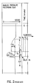
- FIG. 2 shows a typical analog pressure recording during pretest.
- a pressure drawn-down ⁇ p1 is recorded as piston 126 is withdrawn during a time period T1
- a pressure draw-down ⁇ p2 is recorded as piston 128 is withdrawn during a time period T2.
- pretest chambers 122 and 124 are full (at time t2), the pressure begins to build up over a time period ⁇ t toward a final pressure, that of the formation.
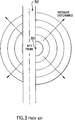
- the permeability has been estimated by analyzing the pressure recording during either buildup or drawdown. As illustrated in Figure 3, the point 310 at which the probe tip 110 is applied to the wall of the borehole 312 coincides with the center of the latter stage of the pressure disturbance dig buildup. From the perspective of a coordinate system whose axes have been suitably stretched by an amount dictated by the horizontal and vertical components of the permeability, the pressure disturbance appears to be propagating spherically outward from the probe tip 110. Thus the analysis yields a single "spherical" permeability value, consisting of a specific combination of both the horizontal and vertical components of the permeability. During drawdown, the pressure disturbance has only been analyzed for the case of a homogeneous formation with isotropic permeability.
- FIG. 4 shows in schematic form a borehole logging device 400 useful in practicing the method.
- formation pressure responses vs. time are measured at two observation probes (402 and 404) of circular cross-section as a transient pressure disturbance is established in the formation 406 surrounding the borehole 408 by means of a "source" probe 410.
- the observation probes are spaced apart in the borehole, probe 404 (the “horizontal” probe) being displaced from source probe 410 in the lateral direction and probe 402 (the “vertical” probe) being displaced from source probe 410 in the longitudinal direction.
- Hydraulic properties of the surrounding formation such as values of the anisotropic permeability and the associated hydraulic anisotropy, are derived from the measured pressure responses.
- the longitudinally-spaced observation probes are set so that they straddle a hydraulic barrier in the formation (e.g., a formation layer of low permeability relative to the layers in which the probes are set), the values determined for vertical permeability and hydraulic anisotropy may differ significantly from the local characteristics of the formation layers above and below the barrier.
- the technique of the Lasseter patent may require simultaneous hydraulic seating of three probes, though it may be possible to make both horizontal and vertical measurements with only two probes. Accurate measurement may be prevented if one or more of the probes fails to seal properly, such as where the borehole surface is uneven. While even a single-probe system can encounter seating problems, the need for simultaneous seating of multiple probes may increase the difficulty of obtaining the desired measurement.
- the measured build-up and draw-down data are analyzed to derive separate values for horizontal and vertical formation permeability. This is possible because they successfully analyze the pressure disturbance during draw-down for an anisotropic formation.
- This technique offers a localized determination of hydraulic anisotropy, and avoids the need to incorporate data from other logging tools or core analysis. It has the disadvantage that it relies on measurement of pressure build-up, which demands an extremely fast-responding pressure transducer with a very high sensitivity.
- Pressure draw-down is a relatively robust measurement -- pressure is measured before and after the pressure disturbance caused by fluid extraction. Pressure build-up is a more delicate measurement because the rate of pressure recovery must be measured accurately as the detected pressure asymptotically approaches formation pressure (the pressure recovers at a rate of 1/t 3/2 ).
- a further technique for determining permeability is performed in the laboratory using formation samples and a laboratory instrument known as a minipermeameter.
- the instrument has an injection probe with a nozzle of circular cross-section which is pressed against the surface of a sample and appropriately sealed. Pressurized gas flows through the injection nozzle into the rock sample as gas flow and injection pressure are measured.
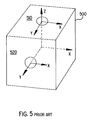
- the process may be performed on a first face 510 having its longitudinal (z) axis perpendicular to the bedding planes of a formation sample 500 and on a second face 520 having its longitudinal (x and y) axis parallel to the bedding planes of the formation sample.
- the measured flows through the sample are used in determining permeability. See, for example, R.
- the minipermeameter is a laboratory instrument, and cannot be used to make in situ measurements in a well bore. Thus, it can only be used to make the necessary measurements if formation core samples are available, which is not always the case. Moreover, it entails destruction of portions of the core sample, as a smaller sample having a smooth face parallel to and perpendicular to the bedding planes must be cut from the sample for testing. Also, the mini-permeameter measures the permeability of isotropic samples, in the case of an anisotropic sample, it only gives an effective value. Thus, it would only give an effective vertical and effective horizontal permeability from the two faces 510 and 520, respectively.
- the invention provides an apparatus for making determinations of horizontal and vertical permeabilities of an earth formation. Further, it provides an apparatus with a single probe for distinguishing between horizontal and vertical permeability in a single measurement. The invention also provides an apparatus which avoids limitations of the prior art methods described above.
- fluid flow measurements are made in situ using a repeat formation tester and a modified probe aperture, or a mini-permeameter with a modified probe aperture.
- the modified probe aperture has an elongate cross-section, such as elliptic or rectangular.
- the probe aperture may include a plurality of openings of varying shapes which are aligned to approximate an elongate aperture.
- a first flow measurement is made with the longer dimension of the probe aperture in a first orientation (e.g., horizontal or vertical) with respect to the formation bedding planes.
- a second flow measurement is made with the probe aperture orthogonal to the first orientation.
- the invention concerns an apparatus including a probe with an elongate aperture for obtaining measurements useful in the estimation of horizontal and/or vertical components of permeability of an anisotropic earth formation.
- the "horizontal” direction is generally parallel to the bedding planes of the rock, and the “vertical” direction is generally perpendicular to the bedding planes of the rock.
- the term "formation” comprises a formation sample, such as a core plug taken from a borehole. These terms have been chosen to simplify explanation of the invention. They should in no way be construed to limit the invention which is defined by the appended claims.
- “formation fluid” may be a liquid or a gas such as atmospheric air.
- flow measurements are made to obtain values from which the permeability components of an earth formation are estimated.
- the flow measurements may be conducted in situ and/or in the laboratory using formation samples.
- In situ measurements are preferably made in a borehole with a formation test tool having a probe aperture modified as described below.
- Formation test tools which may be employed include the Schlumberger RFTTM tester, MRTTTM tester and MDTTM tester.
- Laboratory measurements and measurements on outcrops are preferably made with a mini-permeameter having a probe aperture modified as described below.
- the technique can be performed using a single probe. Pressure measurements are taken at the probe, through which fluid is forced to flow under substantially steady-state, single-phase conditions. For downhole measurements, the flow is preferably induced by drawing formation fluid into the tool through the probe ("draw-down”). Alternatively, fluid may be injected into the formation through the probe ("injection”). Gas injection is preferred for laboratory measurements with formation samples. Whether fluid is drawn into the probe or injected out through the probe, a pressure disturbance is caused in the formation fluid.
- Preferred methods of estimating horizontal and/or vertical permeability in accordance with the invention differ in at least two significant ways from the prior art methods described above.
- a probe having an aperture of non-circular cross-section is employed.
- the probe is that part of the tool or instrument in contact with the formation or formation specimen. Fluid is displaced through the probe aperture in making a measurement.
- the aperture is preferably shaped as a narrow slit, a small aspect ratio (width/length) being of more importance than the exact shape of the cross-section.
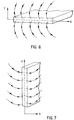
- the slit shape allows fluid to be drawn or injected in a pattern which corresponds to the direction of the measurement. For example, Figure 6 shows the probe oriented horizontally.
- the fluid enters the probe (in the case of draw-down) along the vertical axis Y.
- Figure 7 shows the probe oriented vertically.
- the flow lines in Figure 7 show the fluid entering the probe (in the case of a draw-down) along a horizontal axis X.
- the limit on the smallness of the aspect ratio results from a desire to avoid clogging, and the size of the diameter (maximum length) of the probe.
- the aspect ratio as defined (width/length) is less than 1.0.
- measurements are taken during two pressure disturbances (e.g., during two draw-downs), with the aperture oriented in two different directions with respect to the formation or formation specimen during the two measurements.
- the aperture is oriented in a first direction (e.g., horizontal) during a first draw-down, and is oriented in a second direction (e.g., vertical) orthogonal to the first direction during a second draw-down.
- the "orientation" is the direction of the longest dimension of the aperture cross-section.
- the non-circular aperture cross-section may be generally elliptic or rectangular or of some other elongate or slit-like form.
- pressure draw-downs caused by withdrawal of fluid from the formation
- pressure increases caused by injection of fluid into the formation may be used.
- a combination of a pressure draw-down and a pressure increase (injection) may be used in place of two draw-downs.
- Probes with two different aperture cross-sections may be used for the two pressure disturbance (draw-down and/or injection) measurements -- for example, one of the aperture cross-sections can be circular, provided the other aperture cross-section has a small aspect ratio (ratio of width to length).
- Determination of horizontal and/or vertical permeability in accordance with the preferred embodiments is based upon our derived relationship among the following parameters: the volumetric flow rate, Q, and the viscosity, ⁇ , of the fluid forced to pass through the aperture of the probe during draw-down or injection, the horizontal, k h , and vertical k v , components of the permeability of the formation the pressure at the probe, P p , the pressure of the formation far from the probe (equivalent to the pressure measured by the probe when the formation fluid is in its undisturbed state), P f , and the probe aperture dimensions 2 x 1 h and 2 x 1 v shown in Figure 8.
- FIG. 9 shows a sampling and measuring tool 910 in a well bore such as an uncased borehole 912 penetrating one or more earth formations as at 914.
- Tool 910 is suspended in the borehole 912 from the lower end of a typical multiconductor cable 916 that is spooled in the usual fashion on a suitable winch (not shown) at the surface.
- Tool 910 is coupled to a surface portion 918 of a tool control system comprising control, communication and preprocessing circuitry, a power supply and the like.
- Tool 910 is also coupled to a typical recording and indicating apparatus 918.
- a processor 922 communicates with tool control system portion 918 and with recording and indicating apparatus 920 for receiving and processing data.
- Processor 922 is preferably a suitably-programmed general-purpose computer system, though a suitable special-purpose digital or analog computer could alternatively be employed.
- tool 910 includes a body 924 which encloses a downhole portion of the tool control system, and carries selectively-extendible tool-anchoring means 926.
- Body 924 also carries a probe assembly 928 and multiple fluid-collecting chambers, two such chambers being shown at 930 and 932.
- tool-anchoring means 926 Upon command from the surface, tool-anchoring means 926 is extended and the probe assembly 928 is applied to the formation by the tool control system.
- Probe assembly 928 is equipped for selectively sealing off or isolating selected portions of the wall of the borehole 912, and establishing pressure or fluid communication with the adjacent earth formation, as at 914.
- FIG 10 illustrates schematically the principal elements of a preferred probe assembly 928 and related elements of tool 910 employed in taking measurements in accordance with the invention.
- Probe assembly 928 includes a packer 1010 which is applied to a mudcake layer 1012 of the borehole wall by suitable means such as hydraulically-actuated pistons 1014 and 1016.
- Sampling probes 1018 and 1020 are forced outwardly through apertures in packer 1010 by suitable means so that their tips penetrate the mudcake layer 1012.
- Probes 1018 and 1020 may also be hydraulically-actuated.
- Figure 10 shows packer 1010 and probes 1018 and 1020 in their extended positions, with the apertures of probes 1018 and 1020 in fluid communication with formation 914. Packer 1010 and mudcake layer 1012 effect a seal between formation 914 and the probe apertures.
- Each probe may include a filter disposed in the probe aperture and a filter-cleaning piston.
- probe 1018 includes a filter 1022 and a filter-cleaning piston 1024
- probe 1020 includes a filter 1026 and a filter-cleaning piston 1028.
- Chambers 930 and 932 are fitted with respective pistons 1030 and 1032.
- Pressure is preferably measured before continuously during drawdown through probe 1018 by a pressure sensor shown schematically at 1034.
- pressure is preferably measured before and continuously during drawdown through probe 1020 by a pressure sensor shown schematically at 1036.
- Probes 1018 and 1020 may each have an elongate aperture (e.g., of elliptical or rectangular cross-section) as described above, or one may have an elongate aperture and the other a circular aperture, as described above. Probes 1018 and 1020 need not be part of a single pad assembly, but may, for example, each have an independent pad assembly with independently-operable actuators for applying the pad and probe to the formation.
- the tool may have a single probe (such as probe 1018), the probe being mounted to the tool 910 such that its aperture can be selectively oriented relative to the bedding planes of the formation.
- additional actuating means may be provided for selectively orienting the probe aperture in a horizontal position (as probe 11018 as shown in Figure 10) or in a horizontal position (as probe 1020 as shown in Figure 10).
- a first measurement is made with the aperture in one of the two positions, then the probe is retracted, reoriented and re-applied and a second measurement is made with the aperture in the other of the two positions.
- the probe may have multiple flow channels or ports.
- the apertures are controlled by valves within the formation test tool. Opening and closing the valves appropriately gives a flow configuration with either the long axis along the formation bedding planes or perpendicular to them, as required.
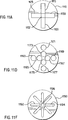
- Many possible configurations of ports are suitable, as shown in the schematic view of Figures 11A-F.
- Figure 11A illustrates schematically a single probe 1110 faced with a sealing material and having multiple apertures. Apertures 1115 and 1120 are oriented in the vertical direction and apertures 1125 and 1130 are oriented in the horizontal direction. Aperture 1132 is centrally located and is operative for both the horizontal and vertical directions.
- the multiple apertures approximate the action of a single elongate opening in the probe which contacts the earth formation.
- Figure 11B shows an alternative embodiment for that shown in Figure 11A.
- a plurality of apertures having a circular cross-section are used to approximate the flow through an elongate opening.
- a central opening 1136 is used for both the horizontal and vertical flow measurement.
- a group of linearly aligned probes of circular cross-section are opened at the same time as center opening 1135.
- a second plurality of linearly aligned openings of circular cross-section 1141 and 1143 are positioned in the horizontal direction. During the horizontal measurement, these openings are activated along with central opening 1135 to obtain vertical permeability.
- the apertures communicate with a manifold 1145 having controllable flow valves 1147.
- flow valve 1147A is activated, and apertures 1137 and 1139 communicate with a pipe leading to the pretest sample chambers of a formation tester (see Figure 1).
- flow valve 1147B is activated and apertures 1141 and 1143 communicate with the sample chambers.
- Aperture 1135 is always communicative with the chambers as it is used for both orientations.
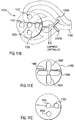
- Figure 11C is a simplified variation of Figure 11B.
- the central aperture 1155 is activated for both the vertical and horizontal flow measurements.
- aperture 1157 is activated while for the vertical direction, aperture 1159 is activated.
- the probe of Figure 11C has the advantage of requiring a less complicated manifold arrangement than that of Figure 11B. Such an embodiment can save costs on materials reducing the cost of the tool
- Figure 11D is another alternative embodiment to that shown in Figures 11B and 11C.
- no central aperture is used. Instead, the horizontal measurement is obtained through four linearly aligned openings 1163, 1165, 1167, and 1169.
- openings 1171, 1173, 1175, and 1177 are activated.
- This embodiment requires a more complicated manifold then that of Figure 11B because it has eight openings as opposed to five.
- FIG. 11E Yet another probe aperture arrangement is shown in Figure 11E.
- multiple elongate apertures are arranged in patterns on the face of probe 1180 such that a group of apertures may be selected to approximate an elongate aperture.
- apertures 1182 and 1184 may be selected to approximate a slit-shaped aperture of one orientation
- apertures 1186 and 1188 may be selected to approximate a slit-shaped aperture in an orthogonal direction.
- FIG. 11F A further probe aperture arrangement is shown in Figure 11F.
- multiple elongate apertures are arranged in patterns on the face of probe 1190 such that a single aperture (e.g., aperture 1192) or pair of apertures (e.g., apertures 1192 or 1194) can be selected by means of a set of controllable valves (not shown).
- Apertures arranged in 45° increments around the probe face allow for selection of apertures most closely oriented in the vertical or horizontal directions when the formation bedding planes cross the borehole at high angles.
- Central aperture 1196 may be activated in combination with any of the outer apertures to more closely approximate an aperture with a smaller aspect ratio.
Landscapes
- Geology (AREA)
- Life Sciences & Earth Sciences (AREA)
- Engineering & Computer Science (AREA)
- Mining & Mineral Resources (AREA)
- Environmental & Geological Engineering (AREA)
- Fluid Mechanics (AREA)
- Physics & Mathematics (AREA)
- General Life Sciences & Earth Sciences (AREA)
- Geochemistry & Mineralogy (AREA)
- Chemical & Material Sciences (AREA)
- Analytical Chemistry (AREA)
- Investigation Of Foundation Soil And Reinforcement Of Foundation Soil By Compacting Or Drainage (AREA)
- Geophysics And Detection Of Objects (AREA)
Applications Claiming Priority (2)
| Application Number | Priority Date | Filing Date | Title |
|---|---|---|---|
| US752724 | 1991-08-30 | ||
| US07/752,724 US5279153A (en) | 1991-08-30 | 1991-08-30 | Apparatus for determining horizontal and/or vertical permeability of an earth formation |
Publications (3)
| Publication Number | Publication Date |
|---|---|
| EP0530105A2 true EP0530105A2 (fr) | 1993-03-03 |
| EP0530105A3 EP0530105A3 (en) | 1993-05-19 |
| EP0530105B1 EP0530105B1 (fr) | 1996-03-13 |
Family
ID=25027543
Family Applications (1)
| Application Number | Title | Priority Date | Filing Date |
|---|---|---|---|
| EP92402349A Expired - Lifetime EP0530105B1 (fr) | 1991-08-30 | 1992-08-27 | Dispositif pour la détermination de la perméabilité horizontale et/ou verticale d'une formation terrestre |
Country Status (4)
| Country | Link |
|---|---|
| US (1) | US5279153A (fr) |
| EP (1) | EP0530105B1 (fr) |
| DE (1) | DE69208978D1 (fr) |
| NO (1) | NO305722B1 (fr) |
Cited By (4)
| Publication number | Priority date | Publication date | Assignee | Title |
|---|---|---|---|---|
| EP0698722A3 (fr) * | 1994-06-17 | 1997-06-04 | Halliburton Co | Méthode pour tester de formations à faible perméabilité |
| GB2394739A (en) * | 2002-11-01 | 2004-05-05 | Schlumberger Holdings | Methods and apparatus for measuring pressure in earth formations |
| WO2007005071A1 (fr) * | 2005-07-05 | 2007-01-11 | Halliburton Energy Services, Inc. | Ensemble outil testeur de formation |
| EP2280147A3 (fr) * | 2003-03-07 | 2011-04-13 | Halliburton Energy Services, Inc. | APPAREIL ET méthode pour tester UNE FORMATION et prélever un échantillon |
Families Citing this family (41)
| Publication number | Priority date | Publication date | Assignee | Title |
|---|---|---|---|---|
| US5431227A (en) * | 1993-12-20 | 1995-07-11 | Atlantic Richfield Company | Method for real time process control of well stimulation |
| US5538090A (en) * | 1995-04-10 | 1996-07-23 | Siler; Gary W. | Ground probe apparatus |
| US5549159A (en) * | 1995-06-22 | 1996-08-27 | Western Atlas International, Inc. | Formation testing method and apparatus using multiple radially-segmented fluid probes |
| US5703286A (en) * | 1995-10-20 | 1997-12-30 | Halliburton Energy Services, Inc. | Method of formation testing |
| US5934374A (en) * | 1996-08-01 | 1999-08-10 | Halliburton Energy Services, Inc. | Formation tester with improved sample collection system |
| AU2001283388A1 (en) * | 2000-08-15 | 2002-02-25 | Baker Hughes Incorporated | Formation testing apparatus with axially and spirally mounted ports |
| US6769296B2 (en) * | 2001-06-13 | 2004-08-03 | Schlumberger Technology Corporation | Apparatus and method for measuring formation pressure using a nozzle |
| US6658930B2 (en) | 2002-02-04 | 2003-12-09 | Halliburton Energy Services, Inc. | Metal pad for downhole formation testing |
| EP1512152A4 (fr) * | 2002-05-17 | 2006-03-08 | Halliburton Energy Serv Inc | Procede et appareil d'essai de couches pour mesure en cours de forage |
| AU2003231797C1 (en) * | 2002-05-17 | 2010-02-18 | Halliburton Energy Services, Inc. | MWD formation tester |
| US6719049B2 (en) * | 2002-05-23 | 2004-04-13 | Schlumberger Technology Corporation | Fluid sampling methods and apparatus for use in boreholes |
| US8555968B2 (en) * | 2002-06-28 | 2013-10-15 | Schlumberger Technology Corporation | Formation evaluation system and method |
| US8210260B2 (en) | 2002-06-28 | 2012-07-03 | Schlumberger Technology Corporation | Single pump focused sampling |
| US8899323B2 (en) | 2002-06-28 | 2014-12-02 | Schlumberger Technology Corporation | Modular pumpouts and flowline architecture |
| US7178591B2 (en) * | 2004-08-31 | 2007-02-20 | Schlumberger Technology Corporation | Apparatus and method for formation evaluation |
| WO2004020982A1 (fr) * | 2002-08-27 | 2004-03-11 | Halliburton Energy Services, Inc. | Appareil et procede d'echantillonnage en une seule phase |
| US7331223B2 (en) * | 2003-01-27 | 2008-02-19 | Schlumberger Technology Corporation | Method and apparatus for fast pore pressure measurement during drilling operations |
| US9376910B2 (en) | 2003-03-07 | 2016-06-28 | Halliburton Energy Services, Inc. | Downhole formation testing and sampling apparatus having a deployment packer |
| EP1642156B1 (fr) * | 2003-05-02 | 2020-03-04 | Halliburton Energy Services, Inc. | Systemes et procedes pour la diagraphie par resonance magnetique nucleaire |
| US7178392B2 (en) * | 2003-08-20 | 2007-02-20 | Schlumberger Technology Corporation | Determining the pressure of formation fluid in earth formations surrounding a borehole |
| BRPI0414998A (pt) | 2003-10-03 | 2006-11-21 | Halliburton Energy Serv Inc | métodos para identificar gás em uma formação geológica, para analisar formações geológicas, e de rmn para analisar formações geológicas, e sistema |
| US7224162B2 (en) * | 2003-10-04 | 2007-05-29 | Halliburton Energy Services Group, Inc. | System and methods for upscaling petrophysical data |
| US7121338B2 (en) * | 2004-01-27 | 2006-10-17 | Halliburton Energy Services, Inc | Probe isolation seal pad |
| AU2005218573B2 (en) * | 2004-03-01 | 2009-05-21 | Halliburton Energy Services, Inc. | Methods for measuring a formation supercharge pressure |
| US7260985B2 (en) * | 2004-05-21 | 2007-08-28 | Halliburton Energy Services, Inc | Formation tester tool assembly and methods of use |
| US7216533B2 (en) * | 2004-05-21 | 2007-05-15 | Halliburton Energy Services, Inc. | Methods for using a formation tester |
| US7261168B2 (en) * | 2004-05-21 | 2007-08-28 | Halliburton Energy Services, Inc. | Methods and apparatus for using formation property data |
| GB2429484B (en) * | 2004-05-21 | 2009-10-28 | Halliburton Energy Serv Inc | Methods and apparatus for measuring formation properties |
| US7603897B2 (en) * | 2004-05-21 | 2009-10-20 | Halliburton Energy Services, Inc. | Downhole probe assembly |
| US7380599B2 (en) * | 2004-06-30 | 2008-06-03 | Schlumberger Technology Corporation | Apparatus and method for characterizing a reservoir |
| AU2008201184B2 (en) * | 2004-10-07 | 2010-01-14 | Schlumberger Technology B.V. | Apparatus and method for formation evaluation |
| US7458419B2 (en) * | 2004-10-07 | 2008-12-02 | Schlumberger Technology Corporation | Apparatus and method for formation evaluation |
| US7654321B2 (en) * | 2006-12-27 | 2010-02-02 | Schlumberger Technology Corporation | Formation fluid sampling apparatus and methods |
| WO2010008684A2 (fr) * | 2008-07-15 | 2010-01-21 | Schlumberger Canada Limited | Appareil et procédés de caractérisation d’un gisement |
| US8015867B2 (en) * | 2008-10-03 | 2011-09-13 | Schlumberger Technology Corporation | Elongated probe |
| EP2432969B1 (fr) | 2009-05-20 | 2018-06-20 | Halliburton Energy Services, Inc. | Patin de testeur de formation |
| US9790789B2 (en) * | 2012-12-21 | 2017-10-17 | Baker Hughes Incorporated | Apparatus and method for obtaining formation fluid samples |
| US9347299B2 (en) | 2013-12-20 | 2016-05-24 | Schlumberger Technology Corporation | Packer tool including multiple ports |
| US9422811B2 (en) | 2013-12-20 | 2016-08-23 | Schlumberger Technology Corporation | Packer tool including multiple port configurations |
| EP3325767A4 (fr) | 2015-07-20 | 2019-03-20 | Pietro Fiorentini S.P.A. | Systèmes et procédés de surveillance des variations survenant dans une formation au cours d'un écoulement dynamique des fluides |
| US11230923B2 (en) | 2019-01-08 | 2022-01-25 | Mark A. Proett | Apparatus and method for determining properties of an earth formation with probes of differing shapes |
Family Cites Families (9)
| Publication number | Priority date | Publication date | Assignee | Title |
|---|---|---|---|---|
| US2688369A (en) * | 1949-06-16 | 1954-09-07 | W B Taylor | Formation tester |
| US3181608A (en) * | 1961-08-11 | 1965-05-04 | Shell Oil Co | Method for determining permeability alignment in a formation |
| US3396796A (en) * | 1966-12-01 | 1968-08-13 | Schlumberger Technology Corp | Fluid-sampling apparatus |
| US3780575A (en) * | 1972-12-08 | 1973-12-25 | Schlumberger Technology Corp | Formation-testing tool for obtaining multiple measurements and fluid samples |
| US3952588A (en) * | 1975-01-22 | 1976-04-27 | Schlumberger Technology Corporation | Apparatus for testing earth formations |
| US4470456A (en) * | 1983-02-22 | 1984-09-11 | Moutray Iii Waldo W | Borehole sampling tool |
| US4742459A (en) * | 1986-09-29 | 1988-05-03 | Schlumber Technology Corp. | Method and apparatus for determining hydraulic properties of formations surrounding a borehole |
| US4890487A (en) * | 1987-04-07 | 1990-01-02 | Schlumberger Technology Corporation | Method for determining horizontal and/or vertical permeability of a subsurface earth formation |
| US5265015A (en) * | 1991-06-27 | 1993-11-23 | Schlumberger Technology Corporation | Determining horizontal and/or vertical permeability of an earth formation |
-
1991
- 1991-08-30 US US07/752,724 patent/US5279153A/en not_active Expired - Lifetime
-
1992
- 1992-08-27 DE DE69208978T patent/DE69208978D1/de not_active Expired - Lifetime
- 1992-08-27 EP EP92402349A patent/EP0530105B1/fr not_active Expired - Lifetime
- 1992-08-28 NO NO923384A patent/NO305722B1/no unknown
Cited By (12)
| Publication number | Priority date | Publication date | Assignee | Title |
|---|---|---|---|---|
| EP0698722A3 (fr) * | 1994-06-17 | 1997-06-04 | Halliburton Co | Méthode pour tester de formations à faible perméabilité |
| GB2394739A (en) * | 2002-11-01 | 2004-05-05 | Schlumberger Holdings | Methods and apparatus for measuring pressure in earth formations |
| GB2394739B (en) * | 2002-11-01 | 2005-11-16 | Schlumberger Holdings | Methods and apparatus for rapidly measuring pressure in earth formations |
| US7152466B2 (en) | 2002-11-01 | 2006-12-26 | Schlumberger Technology Corporation | Methods and apparatus for rapidly measuring pressure in earth formations |
| EP2280147A3 (fr) * | 2003-03-07 | 2011-04-13 | Halliburton Energy Services, Inc. | APPAREIL ET méthode pour tester UNE FORMATION et prélever un échantillon |
| US8235106B2 (en) | 2003-03-07 | 2012-08-07 | Halliburton Energy Services, Inc. | Formation testing and sampling apparatus and methods |
| US8522870B2 (en) | 2003-03-07 | 2013-09-03 | Halliburton Energy Services, Inc. | Formation testing and sampling apparatus and methods |
| WO2007005071A1 (fr) * | 2005-07-05 | 2007-01-11 | Halliburton Energy Services, Inc. | Ensemble outil testeur de formation |
| GB2442660A (en) * | 2005-07-05 | 2008-04-09 | Halliburton Energy Serv Inc | Formation tester tool assembly |
| GB2442660B (en) * | 2005-07-05 | 2011-06-01 | Halliburton Energy Serv Inc | Formation tester tool assembly |
| US8950484B2 (en) | 2005-07-05 | 2015-02-10 | Halliburton Energy Services, Inc. | Formation tester tool assembly and method of use |
| US9605530B2 (en) | 2005-07-05 | 2017-03-28 | Halliburton Energy Services, Inc. | Formation tester tool assembly and method |
Also Published As
| Publication number | Publication date |
|---|---|
| EP0530105A3 (en) | 1993-05-19 |
| NO305722B1 (no) | 1999-07-12 |
| US5279153A (en) | 1994-01-18 |
| DE69208978D1 (de) | 1996-04-18 |
| NO923384D0 (no) | 1992-08-28 |
| NO923384L (no) | 1993-03-01 |
| EP0530105B1 (fr) | 1996-03-13 |
Similar Documents
| Publication | Publication Date | Title |
|---|---|---|
| EP0530105B1 (fr) | Dispositif pour la détermination de la perméabilité horizontale et/ou verticale d'une formation terrestre | |
| EP0520903B1 (fr) | Procédé pour déterminer la perméabilité horizontale et/ou verticale d'une formation terrestre | |
| EP0697502B1 (fr) | Outil de fond de puits pour la détermination de propriétés de formation | |
| EP1309772B1 (fr) | Appareil d'analyse de formations souterraines dote d'orifices places dans le sens axial et de maniere helicoidale | |
| US4936139A (en) | Down hole method for determination of formation properties | |
| EP0897049B1 (fr) | Procédé et dispositif pour la détermination de la formation de pression | |
| US5269180A (en) | Borehole tool, procedures, and interpretation for making permeability measurements of subsurface formations | |
| US2747401A (en) | Methods and apparatus for determining hydraulic characteristics of formations traversed by a borehole | |
| US5056595A (en) | Wireline formation test tool with jet perforator for positively establishing fluidic communication with subsurface formation to be tested | |
| US5644076A (en) | Wireline formation tester supercharge correction method | |
| EP0698722B1 (fr) | Méthode pour tester de formations à faible perméabilité | |
| US5473939A (en) | Method and apparatus for pressure, volume, and temperature measurement and characterization of subsurface formations | |
| US5770798A (en) | Variable diameter probe for detecting formation damage | |
| US5233866A (en) | Apparatus and method for accurately measuring formation pressures | |
| US5095745A (en) | Method and apparatus for testing subsurface formations | |
| US4799157A (en) | Method for uniquely estimating permeability and skin factor for at least two layers of a reservoir | |
| CA2389123C (fr) | Appareil et methode pour mesurer la pression de formation a l'aide d'une buse | |
| WO2021006930A1 (fr) | Essai en cours de forage | |
| Kuchuk | Interval pressure transient testing with MDT packer-probe module in horizontal wells | |
| EP0176410B1 (fr) | Procédé pour l'estimation individuelle de la perméabilité et de l'effet pariétal de deux couches au moins d'un réservoir | |
| EP0646215B1 (fr) | Procede et appareil de mesure de temperature, de pression et de volume, et de caracterisation de formations souterraines | |
| GB2391944A (en) | Determination of relative permeability from saturation level measurements in a borehole | |
| Kuchuk | Interval Pressure Transient Testing with MDT Packer-Probe Module in Horizontal |
Legal Events
| Date | Code | Title | Description |
|---|---|---|---|
| PUAI | Public reference made under article 153(3) epc to a published international application that has entered the european phase |
Free format text: ORIGINAL CODE: 0009012 |
|
| AK | Designated contracting states |
Kind code of ref document: A2 Designated state(s): DE FR GB IT NL |
|
| PUAL | Search report despatched |
Free format text: ORIGINAL CODE: 0009013 |
|
| AK | Designated contracting states |
Kind code of ref document: A3 Designated state(s): DE FR GB IT NL |
|
| 17P | Request for examination filed |
Effective date: 19931110 |
|
| 17Q | First examination report despatched |
Effective date: 19950518 |
|
| GRAH | Despatch of communication of intention to grant a patent |
Free format text: ORIGINAL CODE: EPIDOS IGRA |
|
| GRAA | (expected) grant |
Free format text: ORIGINAL CODE: 0009210 |
|
| AK | Designated contracting states |
Kind code of ref document: B1 Designated state(s): DE FR GB IT NL |
|
| PG25 | Lapsed in a contracting state [announced via postgrant information from national office to epo] |
Ref country code: NL Free format text: LAPSE BECAUSE OF FAILURE TO SUBMIT A TRANSLATION OF THE DESCRIPTION OR TO PAY THE FEE WITHIN THE PRESCRIBED TIME-LIMIT Effective date: 19960313 Ref country code: IT Free format text: LAPSE BECAUSE OF FAILURE TO SUBMIT A TRANSLATION OF THE DESCRIPTION OR TO PAY THE FEE WITHIN THE PRESCRIBED TIME-LIMIT;WARNING: LAPSES OF ITALIAN PATENTS WITH EFFECTIVE DATE BEFORE 2007 MAY HAVE OCCURRED AT ANY TIME BEFORE 2007. THE CORRECT EFFECTIVE DATE MAY BE DIFFERENT FROM THE ONE RECORDED. Effective date: 19960313 |
|
| REF | Corresponds to: |
Ref document number: 69208978 Country of ref document: DE Date of ref document: 19960418 |
|
| PG25 | Lapsed in a contracting state [announced via postgrant information from national office to epo] |
Ref country code: DE Effective date: 19960614 |
|
| ET | Fr: translation filed | ||
| NLV1 | Nl: lapsed or annulled due to failure to fulfill the requirements of art. 29p and 29m of the patents act | ||
| PLBE | No opposition filed within time limit |
Free format text: ORIGINAL CODE: 0009261 |
|
| STAA | Information on the status of an ep patent application or granted ep patent |
Free format text: STATUS: NO OPPOSITION FILED WITHIN TIME LIMIT |
|
| 26N | No opposition filed | ||
| REG | Reference to a national code |
Ref country code: GB Ref legal event code: IF02 |
|
| PGFP | Annual fee paid to national office [announced via postgrant information from national office to epo] |
Ref country code: FR Payment date: 20030808 Year of fee payment: 12 |
|
| PG25 | Lapsed in a contracting state [announced via postgrant information from national office to epo] |
Ref country code: FR Free format text: LAPSE BECAUSE OF NON-PAYMENT OF DUE FEES Effective date: 20050429 |
|
| REG | Reference to a national code |
Ref country code: FR Ref legal event code: ST |
|
| PGFP | Annual fee paid to national office [announced via postgrant information from national office to epo] |
Ref country code: GB Payment date: 20100825 Year of fee payment: 19 |
|
| GBPC | Gb: european patent ceased through non-payment of renewal fee |
Effective date: 20110827 |
|
| PG25 | Lapsed in a contracting state [announced via postgrant information from national office to epo] |
Ref country code: GB Free format text: LAPSE BECAUSE OF NON-PAYMENT OF DUE FEES Effective date: 20110827 |