EP0530342B1 - Compression sonore - Google Patents
Compression sonoreInfo
- Publication number
- EP0530342B1 EP0530342B1 EP92906841A EP92906841A EP0530342B1 EP 0530342 B1 EP0530342 B1 EP 0530342B1 EP 92906841 A EP92906841 A EP 92906841A EP 92906841 A EP92906841 A EP 92906841A EP 0530342 B1 EP0530342 B1 EP 0530342B1
- Authority
- EP
- European Patent Office
- Prior art keywords
- audio signal
- dynamic range
- signal
- gain
- compressing
- Prior art date
- Legal status (The legal status is an assumption and is not a legal conclusion. Google has not performed a legal analysis and makes no representation as to the accuracy of the status listed.)
- Expired - Lifetime
Links
Images

Classifications
-
- H—ELECTRICITY
- H03—ELECTRONIC CIRCUITRY
- H03G—CONTROL OF AMPLIFICATION
- H03G7/00—Volume compression or expansion in amplifiers
- H03G7/007—Volume compression or expansion in amplifiers of digital or coded signals
-
- H—ELECTRICITY
- H03—ELECTRONIC CIRCUITRY
- H03G—CONTROL OF AMPLIFICATION
- H03G7/00—Volume compression or expansion in amplifiers
- H03G7/002—Volume compression or expansion in amplifiers in untuned or low-frequency amplifiers, e.g. audio amplifiers
Definitions
- This invention relates to dynamic range compression of audio signals and is suitable for use with conventional AM and FM broadcasts of audio signals and with high quality digial audio broadcasts (DAB).
- DAB digial audio broadcasts
- proprietory compression equipment is employed prior to the limiter.
- these devices have an obtrusive effect on "serious" music.
- Dynamic range compression of serious music is usually done by a studio manager who is, for example, familiar with the piece of music which is to have its dynamic range compressed and can make unobtrusive adjustments.
- Digital audio broadcasts will have an ancillary data channel associated with them and it has been proposed that this could carry dynamic range or compression related information.
- receivers could be equipped with circuitry which could adapt the dynamic range of the signal to the listeners requirements.
- a signal transmitted with full dynamic range could be transmitted together with a compression control signal with which the receiver could, if so instructed by the listener, compress the dynamic range by up to, say 20 dB.
- a compressed signal could be broadcast and listeners with hi-fi receivers could set their receivers to re-expand the signal dynamics by part or all of the compression.
- the compression control signal could be sent with a fixed rate of, for example, 24 bits per second.
- GB-A-1595401 shows a gain control method in which a signal is derived and sampled in a succession of time blocks and an ideal signal level is derived for each block. A gain control signal is derived which adjusts the gain applied to that block rapidly towards the ideal signal level.
- DSPs digital signal processors
- the receiver can then perform compression or re-expansion of the signal as required.
- Preferred embodiments of the present invention provide a system for compressing the dynamic range of a signal which will closely approach the actions of a studio manager.
- the system looks ahead in the recorded material to a point substantially in advance of the audio samples being replayed and makes relatively gradual gain adjustments up or down.
- a typical look ahead time for the dynamic range compression technique of the invention would be three seconds.
- the system takes some twenty seconds or so to raise the level of a pianissimo passage or to reduce the level of a fortissimo, unless a dynamic change in the programme from pianissimo to fortissimo is very rapid, e.g. a change in less than three seconds and of such a degree that it is important to reduce gain in time for the fortissimo. In this case a more rapid adaptation overrides the gradual change.
- Table 1 summarises a number of options for full and reduced dynamic range available to the broadcaster, with the compressed data signal with the implicit advantages and disadvantages of each option when applied to the entire programme output (not just to Compact Disc, or other recorded material with a wide dynamic range). Table 1.
- Both the second and third options introduce delay, which can cause problems Gilchrist, N.H.C., 1991. Delay in broadcasting operations. AES 90th Convention (Paris 1991). AES Preprint No. 3033. The extent to which broadcasters and listeners may be able to live with these problems has not been determined. However, both the full dynamic range, and a reduced dynamic range achieved using an "artistic" compression process, may be made available to the listener. If the full dynamic range is broadcast, many (possibly all) portable and mobile receivers will need to incorporate compression processing; in practice this means that most receivers will incorporate the extra processing. If the compressed programme is broadcast, probably only the Hi-Fi receivers will need the extra processing.
- the options listed in Table 1 could be considered to apply only to CD and similar recorded material. Most of the advantages and disadvantages would still apply, but the delay mentioned in the second and third options would no longer be significant because it would be introduced only during the replay of recorded material.
- the receiver would either need to incorporate a delay permanently (typically 3 seconds) or switch the delay in and out, as required. The former arrangement would delay all audio signals and there would be delays before the programme changed on selecting a new transmission,and on switching "on”; the latter risks the loss of a few seconds of programme whenever the compression process is switched off.
- the method of dynamic range compression of the present invention can be implemented in Digital Signal Processor (DSP) based hardware in a manner which will be clear to a man skilled in the art.
- DSP Digital Signal Processor
- the method attempts to copy the rules and behaviour of a studio manager by looking ahead with a "window" into the audio data which is to be compressed. This is done by passing the audio data through a delay so that as the gain at a instance in time, t0 is being calculated, the programme can see the volume levels or sound for a period beyond t0.
- the method is implemented with a series of rules and "motivations" with different priority assigned to them. The greatest priority is, clearly, to prevent the audio reaching the levels where external limiters would cut in, in a conventional system or where peak clipping and consequent severe distortion would occur in a digital system.
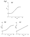
- the method works by using a preset compression law to calculate the ideal gain for a "window" or block of the audio data. Examples of such compression laws are shown in Figure la), b) and c). These give desired output levels for given input levels.
- the method works by looking ahead with a window into the audio data so that the DSP has reasonable warning of sound levels approaching. The DSP is then able to commence adjusting the gain so that a smooth transition is made when some change in gain is needed either to stop a peak level exceeding a predetermined upper limit or to stop a low level signal disappearing into noise.
- Usually such a method enables audio data to be compressed whilst taking account of the transient dynamics of the audio signal.
- the method operates by first looking at the block of sound in the window, provided by a delay, to calculate the peak level of the sound in that window. It then uses a preset compression laws, for example those shown in Figure 1, to calculate the ideal gain for the peak level. If the peak level exceeds a predetermined upper limit then the gain is decreased to keep the peak under the limit when it arrives. In normal circumstances the gain is slowly adjusted to the ideal value derived from the compression law. The gain can be adjusted to reach its ideal level either as the peak level is reached, as the end of the block is reached, or at some later time after that block has been played. In circumstances where the peak level is not going to reach the predetermined upper limit the method can be arranged to adjust the gain gradient applied to the output signal to help maintain the transient dynamics of the music. For example, the gain may be held flat if the dynamics are in danger of impairment.
- a lag is imposed on the gain gradient in excess of the delay used to sample the window into the sound file.
- the rate of increase of gain produced by the gain control signal is such that the ideal gain for the window will not be reached until after that window has been transmitted.
- a quiet sonata with reasonably small dynamic range may be placed within the Studio Managers' guidelines by applying a constant gain throughout. The problems occur when the item begins to sound unnaturally loud. Items with a lot of quiet voals suffer particularly, as a quiet voice has different tonal characteristics to a loud voice, and so, not only does the volume of the voice not match the character of the piece, but the voice may sound unnatural at that volume. Because of this range lifting the piece to the loudest part of the dynamic range is a bad idea. A better imitation of the Studio Managers' guidelines is obtained by using as little gain changing as possible.
- a block diagram of a system embodying the invention is shown in Figure 3 and this comprises an input signal 2 which is fed to a delay 4.
- the output of this delay 4 provides the input to a gain adjuster 6 which also receives a gain adjustment signal via another input and provides a gain adjusted output 8.
- a store 10 is coupled to the input 2 and this stores a block of data at least as long as the delay imposed by the delay 4. This will typically be three seconds long. Audio data received by the input 2 is read into the store 10 in smaller blocks of, for example, 0.25 seconds duration. As each block is read in, the existing blocks are shuffled through the store with some being lost at its end.
- a peak envelope detector 12 generates an array which will be PPM related to the signal level in the block, i.e. the digital level of a sustained sine wave at 1 kilohertz that would give the same PPM reading as the block.
- the characteristics of a PPM are synthesised by simulating the delay and release times of a PPM.
- the one thing that is not simulated, however, is the overshoot characteristic of the PPM, so that when the system is processing music with a lot of short duration peaks there may be a discrepancy between the real and synthesised PPM values of up to 0.5 dB.
- a peak height detector 14 performs a window scanning routine which runs through delayed audio from the store 10 and finds the first peak envelope to go over a predetermined upper limit using the present gain produced by the system. The location of this point is recorded, as is the location and size of the highest peak in the window.
- a peak thresholder 16 is used to determine when peaks exceed the predetermined upper limit.
- a peak does exceed the predetermined upper limit, its position in the block is supplied to the gain gradient calculator 18 by the peak thresholder 16 whilst an ideal gain calculator 20 computes, according to the applicable compression law, what adjustment should be made to the gain to prevent the peak exceeding the predetermined limit.
- the gain gradient calculator 18 then calculates the rate of adjustment which needs to be made to the gain and provides a control signal to the gain adjuster 6 to make the necessary adjustment.
- the highest peak in the window is less than the predetermined upper limit at the existing gain setting then its location and magnitude are passed directly onto the ideal gain calculator 20 and the gain gradient calculator 18. These then compute the required rate of gain adjustment for the gain adjuster 6.
- This control signal for the gain adjuster 6 the gain to move gradually towards the ideal gain for the window. It can be set to move at any rate desired towards this ideal gain but preferably it takes at least as long as the sampled window duration.
- the ideal gain calculator 20 operates by using a preset compression law, examples of which are given in Figure 1.
- the input value of a signal at the present gain setting is compared with a series of points for which the input/output relationship is defined.
- the ideal gain is found by interpolating the relationship between them.
- the gain gradient calculator 18 uses the output value of the ideal gain calculator 20 and time (distance) information generated by the peak height detector 14 when it scans the window of audio data, and in response to this generates a logarithmic gradient in decibels per block length. This gain gradient is then checked to be within the preset gain limits, and may be zeroed if the system is in danger of impairing the dynamics of the music, i.e. if the polarity of the gain gradient is moving in an opposite direction to the instantaneous envelope of the sound data. The gain gradient calculator 18 holds the gain flat in such circumstances.
- a further delay can be provided between the gain gradient calculator 18 and the gain adjuster 6 to include an additional delay in gain adjustment.
- a new gain is then calculated from the gain setting currently on the gain adjuster 6 and the gain gradient.
- the gain is also limited if it is in danger of causing clipping inside the digital domain.
- the various possibilities for transmission discussed above could be used. Firstly the signal could be transmitted in its compressed form, somewhere between full and reduced during dynamic range. Secondly the signal could be transmitted without any gain adjustments made by gain adjuster 6 (i.e. with its full dynamic range) and with the control signal from the gain gradient calculator 18 in a separate data channel. Thirdly the signal could be transmitted with its gain adjusted but with the control signal in the separate data channel and lastly, the signal could be transmitted with its full dynamic range and no control signal, and receivers could be provided with circuitry similar to that in Figure 3 to give the limiter the option to compress the received signal.
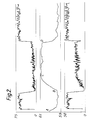
- Figure 2 is a print out of the compression performed on "O Fortuna" from Carmina Burana by Carl Orff.
- the first graph shows the envelope of the original item, the second the gain applied, and the third the envelope of the compressed item.
- the graphs clearly show the compression performed, with more gain being applied in the quiet passage.
- the method detects a large rise in volume, and brings down the gain to bring the peaks below PPM 6.
- the gain continues to fall, until reaching the ideal value for the peaks, coresponding to the compression law. It continues to adjust to the peaks until it reaches point B.
- it detects a fall in the volume of the audio, and brings up the gain to the ideal value for the peaks gain defined by the compression law.
- the compressor could be provided as a unit with analogue or digital input and output, and controls for changing a few of the compression parameters, such as the compression law and the maximum rate of change of gain.
- These controls although redundant for the majority of the time, would enable the Studio Managers to optimise the machine for different situations, say compression for daytime listening and for listening during rush hour driving. For the majority of situations though, the method should cope well with one set of parameters.
Landscapes
- Engineering & Computer Science (AREA)
- Multimedia (AREA)
- Tone Control, Compression And Expansion, Limiting Amplitude (AREA)
- Semiconductor Lasers (AREA)
- Pharmaceuticals Containing Other Organic And Inorganic Compounds (AREA)
- Main Body Construction Of Washing Machines And Laundry Dryers (AREA)
- Control Of Washing Machine And Dryer (AREA)
- Compression, Expansion, Code Conversion, And Decoders (AREA)
Claims (27)
- Un procédé de compression de la plage dynamique d'un signal audio comprenant les étapes consistant à échantillonner des blocs temporels successifs du signal audio, dériver pour chaque bloc du signal audio un niveau de signal préféré, et dériver un signal de commande de gain pour ajuster audit niveau de signal préféré le gain appliqué à ce bloc, caractérisé en ce que le niveau préféré ne sera pas atteint au moins jusqu'à la fin de ce bloc du signal audio.
- Un procédé de compression de la plage dynamique d'un signal audio selon la revendication 1 caractérisé par l'étape consistant à dériver le signal de commande de gain de façon à maintenir sensiblement constant le niveau pendant des augmentations et des diminutions transitoires de l'amplitude dans ce bloc du signal audio.
- Un procédé de compression de la plage dynamique d'un signal audio selon les revendications 1 ou 2 caractérisé en ce que l'étape de dérivation du niveau préféré comprend une détermination de l'amplitude maximale du signal dans ce bloc et une dérivation, à partir de celle-ci, du niveau préféré.
- Un procédé de compression de la plage dynamique d'un signal audio selon les revendications 1, 2 ou 3 caractérisé en ce que le niveau préféré est dérivé d'une loi prédéterminée de compression.
- Un procédé de compression de la plage dynamique d'un signal audio selon la revendication 1, 2, 3 ou 4, caractérisé par l'étape consistant à driver de ce bloc un signal additionnel de commande de gain pour réduire le gain appliqué au bloc lorsqu'une partie du bloc dépasse une limite prédéterminée d'amplitude.
- Un procédé de compression de la plage dynamique d'un signal audio selon la revendication 5 caractérisé en ce que le gain est réduit en un temps suffisant pour empêcher le niveau de signal de dépasser la limite prédéterminée d'amplitude.
- Un procédé de compression de la plage dynamique d'un signal audio selon une revendication précédente quelconque caractérisé en ce que le signal de commande de gain est dérivé d'une manière telle que le niveau préféré sera atteint sensiblement à la fin de ce bloc du signal audio.
- Un procédé de compression de la plage dynamique d'un signal audio selon une revendication précédente quelconque caractérisé en ce que le signal de commande de gain est dérivé de façon à ajuster le gain à une allure maximale de 72 dB par minute.
- Un procédé de compression de la plage dynamique d'un signal audio selon une revendication précédente quelconque caractérisé par les étapes consistant à échantillonner des sous-blocs successifs du signal audio et à échantillonner ainsi des blocs qui se recouvrent, et dériver un signal de commande de gain pour chacun des blocs qui se recouvrent.
- Un procédé de compression de la plage dynamique d'un signal audio selon une revendication précédente quelconque, caractérisé en ce que le signal audio est un signal numérique.
- Un procédé de compression de la plage dynamique d'un signal audio selon l'une quelconque des revendications 1 à 10, caractérisé en ce que le signal audio est un signal analogique.
- Un système de compression de la plage dynamique d'un signal audio comprenant un moyen (10) d'échantillonnage successif de bloc temporels de signal audio, un moyen (12, 14) de dérivation d'un niveau préféré de signal pour chaque bloc du signal audio, et un moyen (18, 20) de dérivation d'un signal de commande de gain pour ajuster au niveau préféré de signal le gain appliqué à ce bloc caractérisé en ce que le signal de gain est dérivé d'une manière telle que le niveau préféré de signal ne sera pas atteint avant au moins la fin de ce bloc.
- Un système de compression de la plage dynamique d'un signal audio selon la revendication 12 caractérisé en ce que le moyen de dérivation du signal de commande intervient pour produire un signal de commande de gain qui maintiendra sensiblement constant le niveau de signal audio pendant des augmentations et des diminutions transitoires de l'amplitude dans ce bloc ou le signal audio.
- Un système de compression de la plage dynamique d'un signal audio selon les revendications 12 ou 13, caractérisé en ce que le moyen de dérivation du niveau préféré de signal inclut un moyen de détermination de l'amplitude maximale du signal audio (14) dans ce bloc.
- Un système de compression de la plage dynamique d'un signal audio selon les revendications 12, 13 ou 14, caractérisé en ce que le moyen de dérivation du niveau préféré de signal intervient selon une loi prédéterminée de compression pour dériver le niveau préféré.
- Un système de compression de la plage dynamique d'un signal audio selon la revendication 12, 13, 14 ou 15, caractérisé par un moyen (16) destiné à détecter quand l'amplitude du bloc du signal audio dépasse une limite prédéterminée et un moyen destiné à ajuster le signal de commande de gain d'une manière telle que le gain appliqué à cette portion du signal audio réduit son amplitude à une valeur inférieure à la limite prédéterminée.
- Un système de compression de la plage dynamique d'un signal audio selon la revendication 16 caractérisé en ce que le moyen de dérivation du signal de commande de gain intervient d'une manière telle que le niveau préféré de signal sera sensiblement atteint à la fin de ce bloc du signal audio.
- Un système de compression de la plage dynamique d'un signal audio selon l'une quelconque des revendications 13 à 18 caractérisé en ce que le moyen de dérivation du signal de commande de gain intervient pour produire un signal de commande de gain qui ajustera le gain sensiblement à 72 dB par minute.
- Un système de compression de la plage dynamique d'un signal audio selon l'une quelconque des revendications 12 à 19, caractérisé en ce que le moyen d'échantillonnage échantillonne des sous-blocs successifs du signal audio en échantillonnant ainsi des blocs qui se recouvrent du signal audio, et le moyen de dérivation du signal de commande de gain dérive un signal de commande de gain pour chacun des blocs qui se recouvrent.
- Un système de compression de la plage dynamique d'un signal audio selon l'une quelconque des revendications 12 à 19, caractérisé en ce que le signal audio est un signal numérique.
- Un système de compression de la plage dynamique d'un signal audio selon l'une quelconque des revendications 12 à 19 caractérisé en ce que le signal audio est un signal analogique.
- Un émetteur incluant un système de compression de plage dynamique selon l'une quelconque des revendications 12 à 21.
- Un émetteur selon la revendication 22 susceptible d'intervenir pour transmettre un signal audio non comprimé et un signal de commande de gain qui en est dérivé.
- Un émetteur selon la revendication 22 susceptible d'intervenir pour transmettre un signal audio comprimé et un signal correspondant de commande de gain par lequel le signal audio a été comprimé.
- Un récepteur incluant un système de compression de plage dynamique selon l'une quelconque des revendications 12 à 21.
- Un système de transmission et de réception d'un signal audio non comprimé comprenant un émetteur incluant un système de compression de plage dynamique selon l'une quelconque des revendications 12 à 21 pour dériver un signal de commande de gain pour le signal audio et un récepteur qui répond à un signal audio non comprimé et à un signal de gain qui en est dérivé par un système de compression de plage dynamique, et qui peut intervenir pour comprimer le signal audio en fonction du signal de commande de gain.
- Un système de transmission et de réception d'un signal audio comprimé et d'un signal de commande de gain comprenant un émetteur incluant un système de compression de plage dynamique selon l'une quelconque des revendications 12 à 21 pour dériver le signal audio comprimé et le signal de commande de gain et un récepteur qui répond au signal audio comprimé et au signal de commande de gain et peut intervenir pour mettre en expansion à sa plage dynamique complète le signal audio comprimé.
Applications Claiming Priority (5)
| Application Number | Priority Date | Filing Date | Title |
|---|---|---|---|
| GB91058966 | 1991-03-20 | ||
| GB919105896A GB9105896D0 (en) | 1991-03-20 | 1991-03-20 | Dynamic range compression |
| GB91060145 | 1991-03-21 | ||
| GB919106014A GB9106014D0 (en) | 1991-03-21 | 1991-03-21 | Dynamic range compression |
| PCT/GB1992/000502 WO1992016996A1 (fr) | 1991-03-20 | 1992-03-20 | Compression sonore |
Publications (2)
| Publication Number | Publication Date |
|---|---|
| EP0530342A1 EP0530342A1 (fr) | 1993-03-10 |
| EP0530342B1 true EP0530342B1 (fr) | 1997-12-29 |
Family
ID=26298608
Family Applications (1)
| Application Number | Title | Priority Date | Filing Date |
|---|---|---|---|
| EP92906841A Expired - Lifetime EP0530342B1 (fr) | 1991-03-20 | 1992-03-20 | Compression sonore |
Country Status (10)
| Country | Link |
|---|---|
| US (1) | US5471651A (fr) |
| EP (1) | EP0530342B1 (fr) |
| JP (1) | JPH05508760A (fr) |
| AT (1) | ATE161667T1 (fr) |
| AU (1) | AU1418892A (fr) |
| CA (1) | CA2082171A1 (fr) |
| DE (1) | DE69223701T2 (fr) |
| FI (1) | FI925269A0 (fr) |
| GB (1) | GB2254988B (fr) |
| WO (1) | WO1992016996A1 (fr) |
Families Citing this family (27)
| Publication number | Priority date | Publication date | Assignee | Title |
|---|---|---|---|---|
| JP3342718B2 (ja) | 1993-01-05 | 2002-11-11 | 富士通テン株式会社 | データ格納方式を用いたボリュームコントロール |
| US5530767A (en) * | 1993-12-28 | 1996-06-25 | Nec Corporation | Reception volume limiting circuit |
| US5815532A (en) * | 1996-05-01 | 1998-09-29 | Glenayre Electronics, Inc. | Method and apparatus for peak-to-average ratio control in an amplitude modulation paging transmitter |
| US5892834A (en) * | 1997-06-30 | 1999-04-06 | Ford Motor Company | Audio level dynamic range compression |
| US6067512A (en) * | 1998-03-31 | 2000-05-23 | Rockwell Collins, Inc. | Feedback-controlled speech processor normalizing peak level over vocal tract glottal pulse response waveform impulse and decay portions |
| GB9824776D0 (en) * | 1998-11-11 | 1999-01-06 | Kemp Michael J | Audio dynamic control effects synthesiser |
| FR2795890B1 (fr) * | 1999-06-30 | 2001-09-14 | Sagem | Procede de compression d'un signal numerique |
| DE60027123T2 (de) * | 1999-12-28 | 2006-09-07 | Ntt Docomo Inc. | Schaltung zur Komprimierung des dynamischen Bereich eines Signals |
| WO2002030077A1 (fr) * | 2000-10-05 | 2002-04-11 | Matsushita Electric Industrial Co., Ltd. | Procede d'etablissement du niveau de decision et recepteur de donnees |
| US7406178B2 (en) * | 2001-04-06 | 2008-07-29 | Texas Instruments Incorporated | Efficient digital audio automatic gain control |
| JP2002353758A (ja) * | 2001-05-28 | 2002-12-06 | Pioneer Electronic Corp | 可変信号減衰回路 |
| WO2003063346A2 (fr) * | 2002-01-24 | 2003-07-31 | Koninklijke Philips Electronics N.V. | Technique permettant de reduire la plage dynamique d'un signal et circuit electronique a cet effet |
| TWI233091B (en) * | 2003-11-18 | 2005-05-21 | Ali Corp | Audio mixing output device and method for dynamic range control |
| US7580531B2 (en) * | 2004-02-06 | 2009-08-25 | Cirrus Logic, Inc | Dynamic range reducing volume control |
| US20050213780A1 (en) * | 2004-03-26 | 2005-09-29 | William Berardi | Dynamic equalizing |
| CN1981433A (zh) * | 2004-06-30 | 2007-06-13 | 皇家飞利浦电子股份有限公司 | 自动调整音频信号的音量的方法和系统 |
| JP2006033204A (ja) * | 2004-07-14 | 2006-02-02 | Toshiba Corp | オーディオ信号処理装置 |
| US8166416B2 (en) * | 2005-08-17 | 2012-04-24 | Cyber Group Usa, Inc. | Play menu and group auto organizer system and method for a multimedia player |
| US20080080722A1 (en) * | 2006-09-29 | 2008-04-03 | Carroll Tim J | Loudness controller with remote and local control |
| US20090323859A1 (en) * | 2008-06-26 | 2009-12-31 | Bishop James W | Flexible, Reconfigurable, Power Efficient Transmitter and Method |
| UA101542C2 (ru) * | 2008-12-15 | 2013-04-10 | Долби Лабораторис Лайсензин Корпорейшн | Виртуализатор окружающего звука с динамическим сжатием диапазона и способ |
| US9620131B2 (en) | 2011-04-08 | 2017-04-11 | Evertz Microsystems Ltd. | Systems and methods for adjusting audio levels in a plurality of audio signals |
| DE102012204193B4 (de) * | 2012-03-16 | 2015-10-22 | Algorithmix GmbH Digital Signal Processing Technologies | Audioprozessor und Verfahren zum Verstärken oder Dämpfen eines empfangenen Audiosignals |
| EP2642769B1 (fr) * | 2012-03-20 | 2017-12-13 | Nxp B.V. | Circuit de commande de haut-parleur servant à déterminer des caractéristiques de haut-parleur et/ou des diagnostics |
| US9070371B2 (en) * | 2012-10-22 | 2015-06-30 | Ittiam Systems (P) Ltd. | Method and system for peak limiting of speech signals for delay sensitive voice communication |
| US9608588B2 (en) * | 2014-01-22 | 2017-03-28 | Apple Inc. | Dynamic range control with large look-ahead |
| CN119007736A (zh) * | 2024-07-22 | 2024-11-22 | 深圳市冠旭电子股份有限公司 | 一种音频压缩方法及装置 |
Family Cites Families (7)
| Publication number | Priority date | Publication date | Assignee | Title |
|---|---|---|---|---|
| GB1599401A (en) * | 1978-04-18 | 1981-09-30 | Nat Res Dev | Input signal level control for communications channels |
| US4271499A (en) * | 1978-07-12 | 1981-06-02 | H.F. Communications Corporation | Method and apparatus for digitally implementing a linked compressor-expander telecommunications system |
| GB2179810B (en) * | 1983-09-21 | 1987-10-21 | British Broadcasting Corp | Dynamic range control of a signal |
| GB8701365D0 (en) * | 1987-01-22 | 1987-02-25 | Thomas L D | Signal level control |
| DE3801841A1 (de) * | 1988-01-20 | 1989-08-03 | Deutsche Telephonwerk Kabel | Schaltungsanordnung fuer tastwahlbloecke in kommunikations-endgeraeten |
| US4839906A (en) * | 1988-05-20 | 1989-06-13 | Amaf Industries, Inc. | Processor based linked compressor-expander telecommunications system |
| US5241689A (en) * | 1990-12-07 | 1993-08-31 | Ericsson Ge Mobile Communications Inc. | Digital signal processor audio compression in an RF base station system |
-
1992
- 1992-03-20 JP JP92506546A patent/JPH05508760A/ja active Pending
- 1992-03-20 CA CA002082171A patent/CA2082171A1/fr not_active Abandoned
- 1992-03-20 WO PCT/GB1992/000502 patent/WO1992016996A1/fr not_active Ceased
- 1992-03-20 EP EP92906841A patent/EP0530342B1/fr not_active Expired - Lifetime
- 1992-03-20 DE DE69223701T patent/DE69223701T2/de not_active Expired - Lifetime
- 1992-03-20 FI FI925269A patent/FI925269A0/fi not_active Application Discontinuation
- 1992-03-20 AU AU14188/92A patent/AU1418892A/en not_active Abandoned
- 1992-03-20 GB GB9206065A patent/GB2254988B/en not_active Expired - Lifetime
- 1992-03-20 AT AT92906841T patent/ATE161667T1/de not_active IP Right Cessation
- 1992-03-20 US US07/949,244 patent/US5471651A/en not_active Expired - Lifetime
Also Published As
| Publication number | Publication date |
|---|---|
| ATE161667T1 (de) | 1998-01-15 |
| FI925269L (fi) | 1992-11-19 |
| AU1418892A (en) | 1992-10-21 |
| US5471651A (en) | 1995-11-28 |
| GB9206065D0 (en) | 1992-05-06 |
| EP0530342A1 (fr) | 1993-03-10 |
| GB2254988A (en) | 1992-10-21 |
| FI925269A7 (fi) | 1992-11-19 |
| GB2254988B (en) | 1995-05-10 |
| DE69223701D1 (de) | 1998-02-05 |
| FI925269A0 (fi) | 1992-11-19 |
| WO1992016996A1 (fr) | 1992-10-01 |
| DE69223701T2 (de) | 1998-04-30 |
| JPH05508760A (ja) | 1993-12-02 |
| CA2082171A1 (fr) | 1992-09-21 |
Similar Documents
| Publication | Publication Date | Title |
|---|---|---|
| US5471651A (en) | Method and system for compressing the dynamic range of audio signals | |
| EP0367569B1 (fr) | Système à effet sonore | |
| EP1616386B1 (fr) | Commande du volume et de la compression dans des salles de cinema | |
| US4490843A (en) | Dynamic equalizing | |
| CN100481722C (zh) | 声虚拟现实引擎中增强传送音的系统和方法 | |
| US8787595B2 (en) | Audio signal adjustment device and audio signal adjustment method having long and short term gain adjustment | |
| US4376916A (en) | Signal compression and expansion system | |
| US4381488A (en) | Dynamic volume expander varying as a function of ambient noise level | |
| EP0793896B1 (fr) | Appareil de reproduction de signaux audio | |
| KR20230156156A (ko) | 라우드니스 레벨을 제어하는 오디오 신호 처리 방법 및 장치 | |
| EP1816891A1 (fr) | Circuit électronique audio et méthode de réglage du niveau sonore de celle-ci | |
| US20020090096A1 (en) | Audio amplifier with voltage limiting in response to spectral content | |
| US20040158458A1 (en) | Narrowband speech signal transmission system with perceptual low-frequency enhancement | |
| US8462964B2 (en) | Recording apparatus, recording method, audio signal correction circuit, and program | |
| US4314372A (en) | Methods and means for producing and reproducing transmitted or recorded sound or video signals | |
| JP2002232247A (ja) | 適応音質音量制御装置、並びに、適応音質音量制御装置を用いた音響装置、通信端末装置および情報端末装置 | |
| GB2429346A (en) | User-selectable limits in audio level control | |
| US11877129B2 (en) | Apparatus having an input and an output and having an effect device with volume-regulated audio signals from an audio file | |
| JPH04365210A (ja) | 車載音響再生装置 | |
| Jeffs et al. | Dynamics processors—technology & application tips | |
| GB2093290A (en) | Audio signal amplifier circuit | |
| JPH06177686A (ja) | 音響再生装置 | |
| JP3820294B2 (ja) | 音響装置 | |
| Monroe | A new approach to balanced audio levels in television | |
| JP2002529757A (ja) | 入力信号に対するレベル補償を行なう方法と装置 |
Legal Events
| Date | Code | Title | Description |
|---|---|---|---|
| PUAI | Public reference made under article 153(3) epc to a published international application that has entered the european phase |
Free format text: ORIGINAL CODE: 0009012 |
|
| 17P | Request for examination filed |
Effective date: 19921102 |
|
| AK | Designated contracting states |
Kind code of ref document: A1 Designated state(s): AT BE CH DE DK ES FR GB GR IT LI NL SE |
|
| 17Q | First examination report despatched |
Effective date: 19950413 |
|
| GRAG | Despatch of communication of intention to grant |
Free format text: ORIGINAL CODE: EPIDOS AGRA |
|
| GRAG | Despatch of communication of intention to grant |
Free format text: ORIGINAL CODE: EPIDOS AGRA |
|
| GRAG | Despatch of communication of intention to grant |
Free format text: ORIGINAL CODE: EPIDOS AGRA |
|
| GRAH | Despatch of communication of intention to grant a patent |
Free format text: ORIGINAL CODE: EPIDOS IGRA |
|
| GRAH | Despatch of communication of intention to grant a patent |
Free format text: ORIGINAL CODE: EPIDOS IGRA |
|
| RBV | Designated contracting states (corrected) |
Designated state(s): AT BE CH DE DK ES FR GR IT LI NL SE |
|
| GRAA | (expected) grant |
Free format text: ORIGINAL CODE: 0009210 |
|
| ITF | It: translation for a ep patent filed | ||
| AK | Designated contracting states |
Kind code of ref document: B1 Designated state(s): AT BE CH DE DK ES FR GR IT LI NL SE |
|
| PG25 | Lapsed in a contracting state [announced via postgrant information from national office to epo] |
Ref country code: NL Free format text: LAPSE BECAUSE OF FAILURE TO SUBMIT A TRANSLATION OF THE DESCRIPTION OR TO PAY THE FEE WITHIN THE PRESCRIBED TIME-LIMIT Effective date: 19971229 Ref country code: LI Free format text: LAPSE BECAUSE OF FAILURE TO SUBMIT A TRANSLATION OF THE DESCRIPTION OR TO PAY THE FEE WITHIN THE PRESCRIBED TIME-LIMIT Effective date: 19971229 Ref country code: GR Free format text: LAPSE BECAUSE OF FAILURE TO SUBMIT A TRANSLATION OF THE DESCRIPTION OR TO PAY THE FEE WITHIN THE PRESCRIBED TIME-LIMIT Effective date: 19971229 Ref country code: ES Free format text: THE PATENT HAS BEEN ANNULLED BY A DECISION OF A NATIONAL AUTHORITY Effective date: 19971229 Ref country code: DK Free format text: LAPSE BECAUSE OF NON-PAYMENT OF DUE FEES Effective date: 19971229 Ref country code: CH Free format text: LAPSE BECAUSE OF FAILURE TO SUBMIT A TRANSLATION OF THE DESCRIPTION OR TO PAY THE FEE WITHIN THE PRESCRIBED TIME-LIMIT Effective date: 19971229 Ref country code: BE Free format text: LAPSE BECAUSE OF FAILURE TO SUBMIT A TRANSLATION OF THE DESCRIPTION OR TO PAY THE FEE WITHIN THE PRESCRIBED TIME-LIMIT Effective date: 19971229 Ref country code: AT Free format text: LAPSE BECAUSE OF FAILURE TO SUBMIT A TRANSLATION OF THE DESCRIPTION OR TO PAY THE FEE WITHIN THE PRESCRIBED TIME-LIMIT Effective date: 19971229 |
|
| REF | Corresponds to: |
Ref document number: 161667 Country of ref document: AT Date of ref document: 19980115 Kind code of ref document: T |
|
| REG | Reference to a national code |
Ref country code: CH Ref legal event code: EP |
|
| REF | Corresponds to: |
Ref document number: 69223701 Country of ref document: DE Date of ref document: 19980205 |
|
| ET | Fr: translation filed | ||
| PG25 | Lapsed in a contracting state [announced via postgrant information from national office to epo] |
Ref country code: SE Free format text: LAPSE BECAUSE OF FAILURE TO SUBMIT A TRANSLATION OF THE DESCRIPTION OR TO PAY THE FEE WITHIN THE PRESCRIBED TIME-LIMIT Effective date: 19980329 |
|
| NLV1 | Nl: lapsed or annulled due to failure to fulfill the requirements of art. 29p and 29m of the patents act | ||
| REG | Reference to a national code |
Ref country code: CH Ref legal event code: PL |
|
| PLBE | No opposition filed within time limit |
Free format text: ORIGINAL CODE: 0009261 |
|
| 26N | No opposition filed | ||
| PGFP | Annual fee paid to national office [announced via postgrant information from national office to epo] |
Ref country code: IT Payment date: 20110322 Year of fee payment: 20 |
|
| PGFP | Annual fee paid to national office [announced via postgrant information from national office to epo] |
Ref country code: FR Payment date: 20110412 Year of fee payment: 20 |
|
| PGFP | Annual fee paid to national office [announced via postgrant information from national office to epo] |
Ref country code: DE Payment date: 20110530 Year of fee payment: 20 |
|
| REG | Reference to a national code |
Ref country code: DE Ref legal event code: R071 Ref document number: 69223701 Country of ref document: DE |
|
| REG | Reference to a national code |
Ref country code: DE Ref legal event code: R071 Ref document number: 69223701 Country of ref document: DE |
|
| PG25 | Lapsed in a contracting state [announced via postgrant information from national office to epo] |
Ref country code: DE Free format text: LAPSE BECAUSE OF EXPIRATION OF PROTECTION Effective date: 20120321 |