EP0530588A1 - Système pour le garnissage interne de galeries à travers de parois en béton - Google Patents
Système pour le garnissage interne de galeries à travers de parois en béton Download PDFInfo
- Publication number
- EP0530588A1 EP0530588A1 EP92114084A EP92114084A EP0530588A1 EP 0530588 A1 EP0530588 A1 EP 0530588A1 EP 92114084 A EP92114084 A EP 92114084A EP 92114084 A EP92114084 A EP 92114084A EP 0530588 A1 EP0530588 A1 EP 0530588A1
- Authority
- EP
- European Patent Office
- Prior art keywords
- spools
- sleeve
- wall
- concrete wall
- modular
- Prior art date
- Legal status (The legal status is an assumption and is not a legal conclusion. Google has not performed a legal analysis and makes no representation as to the accuracy of the status listed.)
- Granted
Links
Images

Classifications
-
- E—FIXED CONSTRUCTIONS
- E04—BUILDING
- E04G—SCAFFOLDING; FORMS; SHUTTERING; BUILDING IMPLEMENTS OR AIDS, OR THEIR USE; HANDLING BUILDING MATERIALS ON THE SITE; REPAIRING, BREAKING-UP OR OTHER WORK ON EXISTING BUILDINGS
- E04G15/00—Forms or shutterings for making openings, cavities, slits, or channels
- E04G15/06—Forms or shutterings for making openings, cavities, slits, or channels for cavities or channels in walls of floors, e.g. for making chimneys
- E04G15/061—Non-reusable forms
-
- F—MECHANICAL ENGINEERING; LIGHTING; HEATING; WEAPONS; BLASTING
- F16—ENGINEERING ELEMENTS AND UNITS; GENERAL MEASURES FOR PRODUCING AND MAINTAINING EFFECTIVE FUNCTIONING OF MACHINES OR INSTALLATIONS; THERMAL INSULATION IN GENERAL
- F16L—PIPES; JOINTS OR FITTINGS FOR PIPES; SUPPORTS FOR PIPES, CABLES OR PROTECTIVE TUBING; MEANS FOR THERMAL INSULATION IN GENERAL
- F16L5/00—Devices for use where pipes, cables or protective tubing pass through walls or partitions
-
- F—MECHANICAL ENGINEERING; LIGHTING; HEATING; WEAPONS; BLASTING
- F16—ENGINEERING ELEMENTS AND UNITS; GENERAL MEASURES FOR PRODUCING AND MAINTAINING EFFECTIVE FUNCTIONING OF MACHINES OR INSTALLATIONS; THERMAL INSULATION IN GENERAL
- F16L—PIPES; JOINTS OR FITTINGS FOR PIPES; SUPPORTS FOR PIPES, CABLES OR PROTECTIVE TUBING; MEANS FOR THERMAL INSULATION IN GENERAL
- F16L9/00—Rigid pipes
- F16L9/14—Compound tubes, i.e. made of materials not wholly covered by any one of the preceding groups
- F16L9/153—Compound tubes, i.e. made of materials not wholly covered by any one of the preceding groups comprising only layers of metal and concrete with or without reinforcement
Definitions
- a “wall” may be horizontal, vertical, or at any desired angle; thus, a “wall” may be a floor, a ceiling, or a roof.
- the wall passage may vary to a substantial extent, depending upon the outside diameter of the pipe or conduit and the particular seal to be used.
- the internal diameter required for the wall opening may range from under two inches to two feet or even more.
- One commercial construction uses a steel tube having a length equal to the width of the wall and having an annular steel flange welded to the outside central portion of the sleeve.
- Heavy wall (0.25 to 0.5 inch) steel pipe is usually used.
- the flange serves as a water stop that precludes water seepage along the outer surface of the sleeve, at the interface between the sleeve and the concrete wall.
- the flange also serves as an anchor that precludes axial movement of the wall sleeve.
- This steel wall sleeve construction presents some substantial technical difficulties.
- That wall sleeve starts with a molded resin precursor having cup-like end caps of an outside diameter D formed integrally with the opposite ends of a main sleeve having an inside diameter D.
- the end caps are cut off the main sleeve and mounted in a concrete form, with the sleeve section fitted onto the two cap sections.
- the end caps are removed along with the concrete form, leaving a wall sleeve suitable for use with a conduit and expandable seal, as described above.
- the wall sleeve precursors of U.S. Patent No. 4,625,940 can be used to produce a long wall sleeve by cutting off the end wall of a cap section on one sleeve precursor and inserting it into the end of another precursor from which the complete cap section has been removed. But the resulting extended sleeve leaves much to be desired.
- the two precursors are joined by a thermal weld there is usually a ridge inside the joint and an appreciable reduction in inside diameter.
- the joint is not usually as strong as desired.
- Auxiliary fasteners such as self-tapping screws are often needed, along with a messy external sealant. Screws or other fasteners may project into the sleeve and create an appreciable obstruction in it. Labor expense is substantial, and scrap is usually undesirably high.
- a cylindrical wall sleeve assembly forming an unimpeded passageway of consistent internal diameter through a concrete wall of given width comprises a first unitary one-piece cylindrical molded resin sleeve member having an internal diameter D1; a joint end of the first sleeve member terminates in a substantially flat radial flange having an external diameter D2, with D2>D1.
- a second unitary one-piece cylindrical molded resin sleeve member having an internal diameter D1; a joint end of the second sleeve member terminates in a substantially flat radial flange having an axially projecting outer rim with an internal diameter D2.
- the joint ends of the first and second sleeve members are firmly secured to each other with their radial flanges in abutting engagement to afford an assembled sleeve having an overall length approximately equal to the wall width.
- each end member including a cylindrical body having an external diameter D1 to fit tightly into an open end of the assembled sleeve, each end member having a substantially flat radially outwardly projecting mounting flange at its outer end which limits insertion of the end member into the sleeve; the end member flanges comprise mounting means for mounting the assembly in fixed position between the opposed walls of a concrete form while allowing removal of both end members, upon dismantling of the form, for full exposure of the interior of the sleeve.
- Another object of the invention is to provide a new and improved system for forming a sleeve lined passage through a concrete wall that is simple and inexpensive and that avoids or minimizes the difficulties of the prior art as described above.
- the invention relates to a system of modular spools to be joined together in a unitary stack and mounted in a concrete wall form to create a lined passage of uniform diameter D through a concrete wall molded in the concrete wall form, the concrete wall form including first and second form plates mounted in fixed spaced relation to each other and separated by a wall width W.
- the system includes a multiplicity of modular spools, with each spool comprising an annular shell having an inside diameter D and an axial length less than W; flat front and rear flanges extend outwardly of the front and rear rims, respectively, of the shell.
- first plurality of the spools each having an axial length L1
- a further plurality of the spools each having an axial length L2, with L1 ⁇ L2; the difference between L1 and L2 is of the order of one inch and L2 is no larger than six inches.
- L1 is approximately three inches and L2 is approximately four inches; thus, the spools can be affixed to each other in stacks that accommodate wall widths varying by only about one inch over a wide width range.
- Figs. 1A and 2 illustrate a first modular spool 10 used in a system according to a preferred embodiment of the invention.
- Spool 10 has an inside diameter D and an overall length L1.
- Spool 10 further includes flat front and rear flanges 11 and 12 which extend outwardly from the front and rear rims, respectively, of the central spool shell 14.
- Figs. 1B and 2 illustrate the construction of a second modular sleeve spool 20 used in the same system as spool 10.
- Spool 20 has the same internal diameter D as spool 10. Its overall length L2 is different from the length L1 of spool 10.
- Spool 20 also includes flat front and rear flanges 21 and 22 that project outwardly of the front and rear rims, respectively, of the central shell 24 of the spool.
- Spools 10 and 20 may be fabricated of thin-wall light-weight low carbon steel, preferably zinc plated.
- the steel utilized may be of the 1010 or 1020 variety and the wall thickness for the steel utilized in spools 10 and 20 may be in the range of 20 gauge to 10 gauge.
- the length L1 for spool 10 is preferably three inches and the length L2 for spool 20 is four inches. This makes it possible to combine the spools in stacks to match any desired wall width W (Fig. 3) in increments of one inch, so that these two spool lengths L1 and L2 can accommodate virtually any concrete wall width for a passage of diameter D.
- the flanges on spools 10 and 20 are preferably of uniform height F; typically, F may be about three quarters inch for spools of small diameter D, with larger flange dimensions F for larger spools.
- the inside diameter D of the spools may range from two inches up to about twenty four inches or even larger.
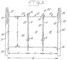
- Fig. 3 shows two spools 10 and one spool 20 fixedly joined together in a unitary stack 30 and mounted in a concrete wall form comprising two form plates 31 and 32 spaced from each other by a wall width W. If the spool lengths L1 and L2 are three inches and four inches, as indicated above, the overall wall thickness W is ten inches. That is, all of the spools in stack 30, together, provide a passage length that is equal to the wall thickness W.
- the mating surfaces of the flanges such as the flange 22 on spool 20 and the flange 11 on the adjacent spool 10, are brushed or otherwise coated with a chemical adhesive.
- the flanges are then pressed together and the adhesive is allowed to set, at least to some extent, to provide initial positioning of the spools relative to each other.
- An appropriate adhesive is silicone adhesive sealant, but others may also be used.
- each mating pair of flanges is spot welded or otherwise joined together; mechanical clinching can be used.
- three spot welds or clinched areas may be employed, as indicated by the welds 16 in Figs. 2 and 3.
- the adhesive used between the flanges remains in place so that the joint between the flanges is essentially waterproof.
- the flanges in the center of stack 30 function as water stops and anchoring plates in the same manner as in conventional wall sleeves.
- one outside flange of the stack is nailed to the inside surface of form member 31, as by nails 35.
- Appropriate nail holes may be provided in the spool flanges 11, 12, 21 and 22. For light-gauge sheet metal spools, however, nail holes may be unnecessary.
- the other outside flange such as the flange 12 at the right hand side of the stack, is engaged by the other form 32. Additional nails 35 may be used to secure flange 12 to plate 32.
- Stack 30 is firmly encased in the wall, in the same manner as a conventional metal or resin wall sleeve. It affords a wall passage of uniform internal diameter D1 through the wall, and thus constitutes an ideal site for a peripheral expandable seal such as the kind disclosed in Barton U.S. Patent No. 3,528,668.
- spools 10 and 20 are formed of thin gauge metal, there is adequate strength due to the short axial lengths L1 and L2 of the spools. Thus, even with light steel construction, the spools are sufficiently strong to be used for wall passages having diameters up to two feet.
- the wall passage is essentially fireproof.
- the modular lengths L1 and L2 accommodate virtually any wall width W.
- For any diameter D it is necessary to stock only two lengths L1 and L2 of the spools; this arrangement is sufficient to accommodate walls of virtually any thickness.
- the inventory required to be able to meet demands for virtually any wall is materially reduced; for any diameter D, a stock of spools of only two lengths L1 and L2 is adequate.
Landscapes
- Engineering & Computer Science (AREA)
- General Engineering & Computer Science (AREA)
- Mechanical Engineering (AREA)
- Architecture (AREA)
- Civil Engineering (AREA)
- Structural Engineering (AREA)
- Forms Removed On Construction Sites Or Auxiliary Members Thereof (AREA)
- Building Environments (AREA)
- Manufacturing Of Tubular Articles Or Embedded Moulded Articles (AREA)
Applications Claiming Priority (2)
| Application Number | Priority Date | Filing Date | Title |
|---|---|---|---|
| US746896 | 1991-08-19 | ||
| US07/746,896 US5509240A (en) | 1991-08-19 | 1991-08-19 | System for forming lined passages through concrete walls |
Publications (2)
| Publication Number | Publication Date |
|---|---|
| EP0530588A1 true EP0530588A1 (fr) | 1993-03-10 |
| EP0530588B1 EP0530588B1 (fr) | 1994-10-26 |
Family
ID=25002822
Family Applications (1)
| Application Number | Title | Priority Date | Filing Date |
|---|---|---|---|
| EP92114084A Expired - Lifetime EP0530588B1 (fr) | 1991-08-19 | 1992-08-18 | Système pour le garnissage interne de galeries à travers de parois en béton |
Country Status (5)
| Country | Link |
|---|---|
| US (1) | US5509240A (fr) |
| EP (1) | EP0530588B1 (fr) |
| AT (1) | ATE113355T1 (fr) |
| CA (1) | CA2076415A1 (fr) |
| DE (1) | DE69200581T2 (fr) |
Families Citing this family (10)
| Publication number | Priority date | Publication date | Assignee | Title |
|---|---|---|---|---|
| US5971444A (en) * | 1996-06-24 | 1999-10-26 | World Fitting, L.L.C. | Through wall connector |
| US6881094B2 (en) * | 1999-12-09 | 2005-04-19 | Power Ease, L.L.C. | Integrated electrical receptacle system for outdoor application |
| CA2327867A1 (fr) * | 1999-12-09 | 2001-06-09 | Robert P. Magyar | Support et dispositif pouvant contenir au moins une connexion electrique |
| US6502364B2 (en) * | 2001-02-12 | 2003-01-07 | Dwayne E. Richardson | Spigot pipe anchor method and apparatus |
| US20040104498A1 (en) * | 2002-12-02 | 2004-06-03 | David Schneider | Tubular sleeve insert for creating a void in precast concrete |
| US8122680B2 (en) * | 2006-07-05 | 2012-02-28 | High Concrete Group Llc | Concrete conduit members |
| US8003889B2 (en) * | 2007-08-02 | 2011-08-23 | Thomas & Betts International, Inc. | Conduit sleeve pass through for concrete construction |
| US9086174B2 (en) * | 2013-03-15 | 2015-07-21 | Securus, Inc. | Extendable sleeve for poured concrete deck |
| US8915038B1 (en) | 2013-05-30 | 2014-12-23 | John D. Crane | Dynamic concrete form |
| PL2899332T3 (pl) * | 2014-01-23 | 2016-09-30 | Zastosowanie przepustu do wbudowania w element ściany lub podłogi |
Citations (4)
| Publication number | Priority date | Publication date | Assignee | Title |
|---|---|---|---|---|
| US3294358A (en) * | 1966-03-04 | 1966-12-27 | Charles L Hagedorn | Pipe sleeve |
| DE2116649A1 (de) * | 1971-04-01 | 1972-10-12 | Guss- Und Armaturwerk Kaiserslautern Nachf. Karl Billand, 6750 Kaiserslautern | Elastische Rohrführung für gemauerte, betonierte oder auf andere Weise hergestellte Gebäudewände, Decken o.dgl |
| DE2528051A1 (de) * | 1975-06-24 | 1977-01-20 | Fersen Dev Ets | Dichtungsvorrichtung fuer mauer-rohrdurchfuehrungen |
| DE7836170U1 (de) * | 1978-12-06 | 1979-03-29 | Passavant-Werke Michelbacher Huette, 6209 Aarbergen | Hoehenanpassbares durchfuehrungsrohr fuer decken, waende o.dgl. |
Family Cites Families (10)
| Publication number | Priority date | Publication date | Assignee | Title |
|---|---|---|---|---|
| US2065072A (en) * | 1930-10-17 | 1936-12-22 | Hertzka Elsa | Spool |
| US3418812A (en) * | 1966-02-14 | 1968-12-31 | Inst Gas Technology | Insulating means for underground storage system |
| US3528668A (en) * | 1967-08-14 | 1970-09-15 | Thunderline Corp | Modular inter-wall seal unit |
| US3914843A (en) * | 1972-09-15 | 1975-10-28 | Us Air Force | Method of connecting a metal conduit to a plastic conduit |
| FI162373A7 (fr) * | 1973-05-18 | 1974-11-19 | Olavi Vaeaenaenen | |
| JPS6212728B2 (fr) * | 1980-08-12 | 1987-03-20 | Tokyo Shibaura Electric Co | |
| DE3146007A1 (de) * | 1981-11-20 | 1983-05-26 | Hans Huber Gmbh & Co Kg, 8434 Berching | "verfahren und vorrichtung zum einbau von mauerdurchfuehrungen" |
| US4625940A (en) * | 1984-05-01 | 1986-12-02 | Thunderline Corporation | Wall sleeves |
| US4598519A (en) * | 1984-09-10 | 1986-07-08 | Reid Daniel B | Composite concrete walls having tie and form spacer |
| US4852319A (en) * | 1988-09-19 | 1989-08-01 | Cowan John D | Combination void drain vent chain |
-
1991
- 1991-08-19 US US07/746,896 patent/US5509240A/en not_active Expired - Lifetime
-
1992
- 1992-08-18 EP EP92114084A patent/EP0530588B1/fr not_active Expired - Lifetime
- 1992-08-18 AT AT92114084T patent/ATE113355T1/de not_active IP Right Cessation
- 1992-08-18 DE DE69200581T patent/DE69200581T2/de not_active Expired - Fee Related
- 1992-08-19 CA CA002076415A patent/CA2076415A1/fr not_active Abandoned
Patent Citations (4)
| Publication number | Priority date | Publication date | Assignee | Title |
|---|---|---|---|---|
| US3294358A (en) * | 1966-03-04 | 1966-12-27 | Charles L Hagedorn | Pipe sleeve |
| DE2116649A1 (de) * | 1971-04-01 | 1972-10-12 | Guss- Und Armaturwerk Kaiserslautern Nachf. Karl Billand, 6750 Kaiserslautern | Elastische Rohrführung für gemauerte, betonierte oder auf andere Weise hergestellte Gebäudewände, Decken o.dgl |
| DE2528051A1 (de) * | 1975-06-24 | 1977-01-20 | Fersen Dev Ets | Dichtungsvorrichtung fuer mauer-rohrdurchfuehrungen |
| DE7836170U1 (de) * | 1978-12-06 | 1979-03-29 | Passavant-Werke Michelbacher Huette, 6209 Aarbergen | Hoehenanpassbares durchfuehrungsrohr fuer decken, waende o.dgl. |
Also Published As
| Publication number | Publication date |
|---|---|
| CA2076415A1 (fr) | 1993-02-20 |
| US5509240A (en) | 1996-04-23 |
| ATE113355T1 (de) | 1994-11-15 |
| EP0530588B1 (fr) | 1994-10-26 |
| DE69200581T2 (de) | 1995-05-04 |
| DE69200581D1 (de) | 1994-12-01 |
Similar Documents
| Publication | Publication Date | Title |
|---|---|---|
| US5967568A (en) | Plastic pipe adaptor for a mechanical joint | |
| EP0160924B1 (fr) | Douilles pour muraille | |
| US5081802A (en) | Method and apparatus for lining manhole assemblies and the like | |
| US5509240A (en) | System for forming lined passages through concrete walls | |
| CA2638143C (fr) | Traversee de manchon de conduit pour construction en beton | |
| US4076281A (en) | Bell fitting and support assembly for pipe | |
| US20050106347A1 (en) | Interlocked strip structure | |
| US5182885A (en) | Extendable wall sleeves | |
| EP0528137B1 (fr) | Méthode et dispositif pour réaliser des réservations dans des parois en béton | |
| US6009914A (en) | Tube compression limiting apparatus and method | |
| JP3447153B2 (ja) | 既設管の更生方法 | |
| JP4014299B2 (ja) | 海洋鋼構造物の壁面の防食帯 | |
| JP2000170235A (ja) | 衛生陶器取付フランジ | |
| KR102822895B1 (ko) | 파형강관 연결구조 | |
| JPH0212382Y2 (fr) | ||
| JP2698924B2 (ja) | 防蝕管路の施工法 | |
| CA1162210A (fr) | Raccord pour canalisation plastique noye dans un plancher en beton | |
| AU8952098A (en) | Fastening system for structural framing elements | |
| JPS6123523Y2 (fr) | ||
| JP3081805B2 (ja) | コンクリート管相互の接合構造 | |
| JPH0316361Y2 (fr) | ||
| JP2003232466A (ja) | 建屋内の配管方法 | |
| JPH01135994A (ja) | リブ付き平鋼 | |
| CA2130059C (fr) | Manchon de traversee avec dispositif coupe-feu | |
| JPH029251Y2 (fr) |
Legal Events
| Date | Code | Title | Description |
|---|---|---|---|
| PUAI | Public reference made under article 153(3) epc to a published international application that has entered the european phase |
Free format text: ORIGINAL CODE: 0009012 |
|
| AK | Designated contracting states |
Kind code of ref document: A1 Designated state(s): AT BE DE FR GB IT NL SE |
|
| 17P | Request for examination filed |
Effective date: 19930622 |
|
| 17Q | First examination report despatched |
Effective date: 19930922 |
|
| GRAA | (expected) grant |
Free format text: ORIGINAL CODE: 0009210 |
|
| AK | Designated contracting states |
Kind code of ref document: B1 Designated state(s): AT BE DE FR GB IT NL SE |
|
| REF | Corresponds to: |
Ref document number: 113355 Country of ref document: AT Date of ref document: 19941115 Kind code of ref document: T |
|
| REF | Corresponds to: |
Ref document number: 69200581 Country of ref document: DE Date of ref document: 19941201 |
|
| ITF | It: translation for a ep patent filed | ||
| ET | Fr: translation filed | ||
| EAL | Se: european patent in force in sweden |
Ref document number: 92114084.4 |
|
| PLBE | No opposition filed within time limit |
Free format text: ORIGINAL CODE: 0009261 |
|
| 26N | No opposition filed | ||
| PGFP | Annual fee paid to national office [announced via postgrant information from national office to epo] |
Ref country code: SE Payment date: 19970821 Year of fee payment: 6 |
|
| PGFP | Annual fee paid to national office [announced via postgrant information from national office to epo] |
Ref country code: AT Payment date: 19970829 Year of fee payment: 6 |
|
| PG25 | Lapsed in a contracting state [announced via postgrant information from national office to epo] |
Ref country code: AT Free format text: LAPSE BECAUSE OF NON-PAYMENT OF DUE FEES Effective date: 19980818 |
|
| PG25 | Lapsed in a contracting state [announced via postgrant information from national office to epo] |
Ref country code: SE Free format text: LAPSE BECAUSE OF NON-PAYMENT OF DUE FEES Effective date: 19980819 |
|
| EUG | Se: european patent has lapsed |
Ref document number: 92114084.4 |
|
| PGFP | Annual fee paid to national office [announced via postgrant information from national office to epo] |
Ref country code: GB Payment date: 20000816 Year of fee payment: 9 |
|
| PGFP | Annual fee paid to national office [announced via postgrant information from national office to epo] |
Ref country code: BE Payment date: 20000823 Year of fee payment: 9 |
|
| PGFP | Annual fee paid to national office [announced via postgrant information from national office to epo] |
Ref country code: FR Payment date: 20000830 Year of fee payment: 9 |
|
| PGFP | Annual fee paid to national office [announced via postgrant information from national office to epo] |
Ref country code: NL Payment date: 20000831 Year of fee payment: 9 |
|
| PGFP | Annual fee paid to national office [announced via postgrant information from national office to epo] |
Ref country code: DE Payment date: 20001025 Year of fee payment: 9 |
|
| PG25 | Lapsed in a contracting state [announced via postgrant information from national office to epo] |
Ref country code: GB Free format text: LAPSE BECAUSE OF NON-PAYMENT OF DUE FEES Effective date: 20010818 |
|
| PG25 | Lapsed in a contracting state [announced via postgrant information from national office to epo] |
Ref country code: BE Free format text: LAPSE BECAUSE OF NON-PAYMENT OF DUE FEES Effective date: 20010831 |
|
| BERE | Be: lapsed |
Owner name: BARTON BRUCE G. JR. Effective date: 20010831 |
|
| PG25 | Lapsed in a contracting state [announced via postgrant information from national office to epo] |
Ref country code: NL Free format text: LAPSE BECAUSE OF NON-PAYMENT OF DUE FEES Effective date: 20020301 |
|
| GBPC | Gb: european patent ceased through non-payment of renewal fee |
Effective date: 20010818 |
|
| PG25 | Lapsed in a contracting state [announced via postgrant information from national office to epo] |
Ref country code: FR Free format text: LAPSE BECAUSE OF NON-PAYMENT OF DUE FEES Effective date: 20020430 |
|
| NLV4 | Nl: lapsed or anulled due to non-payment of the annual fee |
Effective date: 20020301 |
|
| PG25 | Lapsed in a contracting state [announced via postgrant information from national office to epo] |
Ref country code: DE Free format text: LAPSE BECAUSE OF NON-PAYMENT OF DUE FEES Effective date: 20020501 |
|
| REG | Reference to a national code |
Ref country code: FR Ref legal event code: ST |
|
| PG25 | Lapsed in a contracting state [announced via postgrant information from national office to epo] |
Ref country code: IT Free format text: LAPSE BECAUSE OF NON-PAYMENT OF DUE FEES;WARNING: LAPSES OF ITALIAN PATENTS WITH EFFECTIVE DATE BEFORE 2007 MAY HAVE OCCURRED AT ANY TIME BEFORE 2007. THE CORRECT EFFECTIVE DATE MAY BE DIFFERENT FROM THE ONE RECORDED. Effective date: 20050818 |