EP0530751A1 - Appareil et méthode d'enduction - Google Patents
Appareil et méthode d'enduction Download PDFInfo
- Publication number
- EP0530751A1 EP0530751A1 EP92114935A EP92114935A EP0530751A1 EP 0530751 A1 EP0530751 A1 EP 0530751A1 EP 92114935 A EP92114935 A EP 92114935A EP 92114935 A EP92114935 A EP 92114935A EP 0530751 A1 EP0530751 A1 EP 0530751A1
- Authority
- EP
- European Patent Office
- Prior art keywords
- coating
- width
- nozzle
- seal member
- Prior art date
- Legal status (The legal status is an assumption and is not a legal conclusion. Google has not performed a legal analysis and makes no representation as to the accuracy of the status listed.)
- Granted
Links
Images

Classifications
-
- B—PERFORMING OPERATIONS; TRANSPORTING
- B05—SPRAYING OR ATOMISING IN GENERAL; APPLYING FLUENT MATERIALS TO SURFACES, IN GENERAL
- B05C—APPARATUS FOR APPLYING FLUENT MATERIALS TO SURFACES, IN GENERAL
- B05C5/00—Apparatus in which liquid or other fluent material is projected, poured or allowed to flow on to the surface of the work
- B05C5/02—Apparatus in which liquid or other fluent material is projected, poured or allowed to flow on to the surface of the work the liquid or other fluent material being discharged through an outlet orifice by pressure, e.g. from an outlet device in contact or almost in contact, with the work
- B05C5/0254—Coating heads with slot-shaped outlet
-
- B—PERFORMING OPERATIONS; TRANSPORTING
- B05—SPRAYING OR ATOMISING IN GENERAL; APPLYING FLUENT MATERIALS TO SURFACES, IN GENERAL
- B05C—APPARATUS FOR APPLYING FLUENT MATERIALS TO SURFACES, IN GENERAL
- B05C11/00—Component parts, details or accessories not specifically provided for in groups B05C1/00 - B05C9/00
- B05C11/10—Storage, supply or control of liquid or other fluent material; Recovery of excess liquid or other fluent material
- B05C11/1002—Means for controlling supply, i.e. flow or pressure, of liquid or other fluent material to the applying apparatus, e.g. valves
-
- B—PERFORMING OPERATIONS; TRANSPORTING
- B05—SPRAYING OR ATOMISING IN GENERAL; APPLYING FLUENT MATERIALS TO SURFACES, IN GENERAL
- B05C—APPARATUS FOR APPLYING FLUENT MATERIALS TO SURFACES, IN GENERAL
- B05C5/00—Apparatus in which liquid or other fluent material is projected, poured or allowed to flow on to the surface of the work
- B05C5/007—Slide-hopper coaters, i.e. apparatus in which the liquid or other fluent material flows freely on an inclined surface before contacting the work
- B05C5/008—Slide-hopper curtain coaters
-
- G—PHYSICS
- G03—PHOTOGRAPHY; CINEMATOGRAPHY; ANALOGOUS TECHNIQUES USING WAVES OTHER THAN OPTICAL WAVES; ELECTROGRAPHY; HOLOGRAPHY
- G03C—PHOTOSENSITIVE MATERIALS FOR PHOTOGRAPHIC PURPOSES; PHOTOGRAPHIC PROCESSES, e.g. CINE, X-RAY, COLOUR, STEREO-PHOTOGRAPHIC PROCESSES; AUXILIARY PROCESSES IN PHOTOGRAPHY
- G03C1/00—Photosensitive materials
- G03C1/74—Applying photosensitive compositions to the base; Drying processes therefor
-
- B—PERFORMING OPERATIONS; TRANSPORTING
- B05—SPRAYING OR ATOMISING IN GENERAL; APPLYING FLUENT MATERIALS TO SURFACES, IN GENERAL
- B05C—APPARATUS FOR APPLYING FLUENT MATERIALS TO SURFACES, IN GENERAL
- B05C9/00—Apparatus or plant for applying liquid or other fluent material to surfaces by means not covered by any preceding group, or in which the means of applying the liquid or other fluent material is not important
- B05C9/06—Apparatus or plant for applying liquid or other fluent material to surfaces by means not covered by any preceding group, or in which the means of applying the liquid or other fluent material is not important for applying two different liquids or other fluent materials, or the same liquid or other fluent material twice, to the same side of the work
-
- G—PHYSICS
- G03—PHOTOGRAPHY; CINEMATOGRAPHY; ANALOGOUS TECHNIQUES USING WAVES OTHER THAN OPTICAL WAVES; ELECTROGRAPHY; HOLOGRAPHY
- G03C—PHOTOSENSITIVE MATERIALS FOR PHOTOGRAPHIC PURPOSES; PHOTOGRAPHIC PROCESSES, e.g. CINE, X-RAY, COLOUR, STEREO-PHOTOGRAPHIC PROCESSES; AUXILIARY PROCESSES IN PHOTOGRAPHY
- G03C1/00—Photosensitive materials
- G03C1/74—Applying photosensitive compositions to the base; Drying processes therefor
- G03C2001/7492—Slide hopper for head or curtain coating
Definitions
- This invention relates to a method of coating a belt-shaped flexible support with a coating solution to manufacture photographing photo-sensitive materials such as photographing film and photographic paper, photographic printing plate materials, photo-sensitive sheets, heat-sensitive sheets, magnetic materials, and so forth, and an apparatus for practicing the method, and more particularly to a coating method in which a coating width is changed, and an apparatus for practicing the method.
- the guide board preferably the guide board and the spacer for regulating the width of the slit of the coating nozzle, and the pocket plug for regulating the width of the pocket of the coating nozzle are moved according to the coating width, or exchanged for those different in dimension, and the speed of rotation of the coating solution supplying pump is also changed according to the coating width.
- the operation of the coating apparatus is suspended for about one hour. During this pause period, the apparatus is lowered in work efficiency, and the coating solution is wasted.
- This difficulty is serious especially in the manufacture of a photographing photo-sensitive material. That is, if the supplying of the coating solution is stopped during the pause period, then it will be solidified. In order to overcome this difficulty, even if the apparatus is stopped, a small quantity of coating solution is kept supplied to the extent that it is not solidified. This loss of the coating solution during the pause period cannot be disregarded. On the other hand, in order to change the coating width, it may be necessary to remove the coating solution from the coating nozzle; however, if the coating solution is removed in this manner, then it is essential to wash the coating nozzle before the coating operation is started again.
- One of the apparatuses disclosed by Japanese Utility Model (OPI) No. 120974/1989 is so designed that the end of a base board (or support) is detected to drive a masking bar, and, when the width of the base board is changed, control is so made as to make the coating width constant, or to make the non-coating width constant.
- Another apparatus disclosed thereby is free from problems that the coating solution leaks to the backup roll, thus lowering the yield.
- Those apparatuses are still disadvantageous in that they also suffer from the above-described two difficulties, and with a support constant in width, the coating width cannot be freely changed according to the size of a product to be formed.
- the coating width is changed by exchanging the spacer member; that is, the coating width cannot be changed without suspension of the operation of the apparatus.
- an object of this invention is to eliminate the above-described difficulties accompanying a conventional coating method or apparatus.
- an object of the invention is to provide a coating method in which a period of time required for changing a coating width is minimized, or zeroed.
- Another object of the invention is to provide a coating apparatus with which a loss of coating solution which otherwise incurs when a coating width is changed is minimized or zeroed, and the coating width can be changed while a coating operation is being performed; that is, even when the coating width is changed, a coating solution layer formed on the support is uniform in thickness.
- a further object of the invention is to provide a coating apparatus in which the leakage of coating solution from the coating nozzle is minimized, and even when the coating solution has leaked more or less and has been solidified, the coating operation is carried out smoothly.
- a coating method in which a coating solution supplied to a coating nozzle is applied through a slit in the coating nozzle to a belt-shaped flexible support which is continuously run, in which, according to the invention, when a coating width is changed, the coating solution is changed in flow rate so that a coating solution layer formed on the support by the coating solution is uniform in thickness.
- a coating apparatus in which a coating solution supplied to a coating nozzle is applied through a slit in the coating nozzle to a belt-shaped flexible support which is continuously run, which comprises: a coating width regulating member including parts which are inserted into a pocket and a slit in the coating nozzle and/or a guide board; a seal member for preventing the leakage of the coating solution from an inserting hole through which the part of the coating width regulating member is inserted into the pocket; and drive means for moving the coating width regulating member and the seal member in a direction of width of the coating nozzle.
- the seal member is made of an elastic material.
- the seal member comprises: a cup-shaped head portion equal in sectional area to the pocket; and a barrel portion integral with the head portion which is smaller in sectional area to the pocket.
- the head portion is radially outwardly spread even with a small force applied to the end face of the barrel portion, thus providing a sealing effect.
- the guide board has a washing water supplying hole in its surface which is brought into contact with the opening of the slit of the coating nozzle.
- the coating nozzle has a slit or slits; that is, it includes both an extrusion type coating nozzle, and a slide hopper type coating nozzle. More specifically, the coating nozzle includes not only one having one slit but also one having a plurality of slits for forming a plurality of coating solution layers simultaneously.
- the coating method and the coating apparatus according to the invention include methods of forming extrusion coatings, bead coatings, and curtain coatings, and apparatuses for practicing the methods.
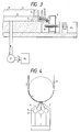
- a coating nozzle 2 is used to apply a coating solution to a belt-shaped flexible support 1 which is run continuously.
- the coating solution is supplied from a coating solution supplying pump P driven by an electric motor M2.
- a coating width regulating member is used which comprises a part which is inserted into a pocket, and a part inserted into a slit and/or a guide. That is, the coating width regulating member is used to change the flow rate of coating solution according to a given change in coating width.
- the speed of rotation of a motor M2, which is drive means for moving the coating width regulating member in a direction of width of the coating nozzle is controlled.
- a control unit may be employed in which a computer specifies a suitable speed of rotation for the motor M2 so that the flow rate of coating solution be proportional to the given coating width.
- the coating width regulating member comprises at least a guide board 3 in the case of FIG. 1; preferably, the guide board 3, a spacer 4 inserted into the slit of the coating nozzle, and a pocket plug 5 inserted into the pocket of the latter in combination.
- it comprises: at least a spacer 4 inserted into a slit; preferably the spacer 4 and a pocket plug 5 in combination.
- a seal member 12 is provided for prevention of the leakage of coating solution from a pocket plug inserting hole into which the pocket plug of the coating width regulating member is inserted. More specifically, the seal member is used to prevent the coating solution from leaking through the gap between the pocket 6 and the pocket plug 5, and it is shaped as shown in FIGS. 1, 3 and 5.
- the seal member 12 is made of an elastic material such as natural rubber, synthetic rubber, and sponge.
- An air cylinder 7 is used to push the seal member 12 so that its end face is radially outwardly spread to sealingly close the gap between the packet 6 and the pocket plug 5.
- the aforementioned drive means for moving the coating width regulating member and the seal member in a direction of width of the coating nozzle operates to move the coating width regulating member according to a given coating width so that the coating width is changed. For this purpose, it transmits the rotation of an electric motor M1 through a screw 8 to a frame 9.
- the guide board 3 is moved according to a given coating width, and it is generally made of synthetic resin.
- the guide board 3 is held pushed against the coating nozzle 2 by guide board pushing means, namely, an air cylinder 10; however, when it is required to move the guide board for the purpose of changing the coating width, the pushing force of the air cylinder 10 is reduced or zeroed so that the guide board can be displaced smoothly.
- guide board pushing means is not limited to the air cylinder 10.
- the spacer 4 of the coating width regulating member which is inserted into the slit of the coating nozzle, is to prevent the leakage of coating solution from a spacer inserting hole which is located laterally of the slit 11, and to regulate a coating width.
- the spacer 4 is generally made of metal or synthetic resin.
- the thickness of the spacer 4 is smaller by 0 to 0.05 mm than the internal dimension of the slit, so that the leakage of coating solution therefrom is minimized.
- the pocket plug 5 of the coating width regulating member is to prevent the leakage of coating solution from a pocket plug inserting hole which is located laterally of the pocket 6 and through which the pocket plug 5 is inserted into the pocket, and to regulate a coating width.
- the pocket plug 5 is generally made of synthetic resin.
- the gap between the pocket 6 and the pocket plug 5 should be minimized to prevent the leakage of coating solution therefrom. However, if the gap is extremely small, then it is necessary to apply a great force to move the pocket plug. Hence, the gap is generally ranged from 0.03 mm to 0.2 mm. With the gap, the leakage of coating solution occurs, and therefore it is necessary to use the seal member 12.
- the spacer 4 and the pocket plug 5 must be moved together; that is, they should function in association with each other.
- the material of the pocket plug 5 is not limited to synthetic resin only.
- it may be made of elastic material such as rubber so that it provides a sealing effect.
- the seal member 12 is to prevent the leakage of coating solution from the pocket plug inserting hole. Therefore, the seal member may be so modified as to be inserted into the pocket.
- the seal member is made of elastic material in such a manner that its external dimension is slightly larger than the internal dimension of the pocket.
- the seal member is formed in such a manner that its external dimension is equal to or slightly smaller than the internal dimension of the pocket, and the end face of the seal member thus formed is pushed against the coating nozzle through a bushing 13 by the air cylinder 7 so that it is spread radially outwardly.
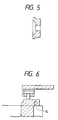
- the seal member shown in FIG. 1 or 3 is in the form of a flat plate. In order to spread the seal member radially outwardly, it is necessary to apply a relatively great force to it. This difficulty may be eliminated by modifying the seal member as shown in FIG. 5. That is, the seal member shown in FIG. 5 comprises: a cup-shaped head portion which is equal in sectional area to the pocket; and a barrel portion integral with the head portion which is smaller in sectional area than the pocket. The head portion of the seal member is readily spread radially outwardly with a relatively small force applied to the end face of the barrel portion.
- the seal member When it is required to change the coating width, the seal member may be moved as it is (spread); however, the force applied to the end face of the barrel portion should be reduced or zeroed to move it smoothly.
- the air cylinder 7 is employed for pushing the end face of the seal member; however, the invention is not limited thereto or thereby.
- the seal member may be in the form of a rubber balloon, which is used as follows: During the coating operation, the rubber balloon is inflated to provide a sealing effect.
- the pocket, the pocket plug, and the seal member are circular; however, the invention is not limited thereto or thereby.
- the movement of the coating width regulating member and the seal member in a direction of width of the coating nozzle may be achieved, for instance, by a servo motor, pulse motor, air cylinder or manual handle.
- the gap between the slit 11 and the spacer 4 is reduced, and the seal member is employed in the above-described manner, the leakage of coating solution can be minimized.
- the coating solution may leak from the gap between the slit 11 and the spacer 4 and from around the pocket plug 5, although its quantity is considerably small.
- the coating solution thus leaked is solidified with time, thus catching the pocket plug or the spacer in the coating nozzle. This results in a difficulty that, when it is required to change the coating width, the pocket plug or the spacer cannot be moved.
- a water supplying hole 14 is formed in the guide board set above the slit. That is, a washing water is supplied through the water supplying hole 14 to the end of the slit 11 and the end of the pocket to wash them, thereby to prevent the pocket plug or the spacer from being caught in the coating nozzle.
- the water supplying hole is formed in the guide member; however, it goes without saying that the water supplying hole may be formed in a component other than the guide member.
- the technical concept of the invention may be applied to a film forming extrusion die, laminating extrusion die, and so forth.
- a coating solution for forming a photographing photo-sensitive material was applied to a polyethylene terephthalate support 180 ⁇ m in thickness and 1200 mm in width at a coating speed of 100 m/min.
- the coating width was changed from 1170 mm to 1120 mm.
- the speed of movement of the coating width regulating member was 2 mm/sec., and it took 25 sec. to change the width as much as 50 mm.
- the coating solution supplying conditions were changed with the speed of movement of the coating width regulating member as indicated in the following Table 1: Table 1 coating width flowing rate speed of rotation of the coating solution pump (motor) 1170 mm 4.68 l/min. 1000 r.p.m. 1120 mm 4.48 l/min. 957.26 r.p.m.
- the seal member as shown in FIG. 5 was employed (which, as was described before, has the cup-shaped head portion equal in sectional area to the pocket, and the barrel portion smaller in sectional area the pocket).
- the seal member pushing force was 15 kg when a coating operation was carried out, and 3 kg when the coating width regulating member was moved.
- the air cylinder 10 was so adjusted that the guide member pushing force was 100 kg/(whole width) when the coating operation was carried out, and 20 kg/(whole width) when the coating width regulating member was moved.
- the gap between the slit and the spacer was 0.02 mm.
- the flow rate of the washing water was 50 cc/min. which was supplied through the water supplying hole 14 formed in the guide board.
Landscapes
- Chemical & Material Sciences (AREA)
- Engineering & Computer Science (AREA)
- Materials Engineering (AREA)
- Physics & Mathematics (AREA)
- General Physics & Mathematics (AREA)
- Coating Apparatus (AREA)
- Application Of Or Painting With Fluid Materials (AREA)
Applications Claiming Priority (3)
| Application Number | Priority Date | Filing Date | Title |
|---|---|---|---|
| JP24647491 | 1991-09-02 | ||
| JP246474/91 | 1991-09-02 | ||
| JP3246474A JPH07171467A (ja) | 1991-09-02 | 1991-09-02 | 塗布方法及び装置 |
Publications (2)
| Publication Number | Publication Date |
|---|---|
| EP0530751A1 true EP0530751A1 (fr) | 1993-03-10 |
| EP0530751B1 EP0530751B1 (fr) | 1999-07-14 |
Family
ID=17148941
Family Applications (1)
| Application Number | Title | Priority Date | Filing Date |
|---|---|---|---|
| EP92114935A Expired - Lifetime EP0530751B1 (fr) | 1991-09-02 | 1992-09-01 | Appareil et méthode d'enduction |
Country Status (3)
| Country | Link |
|---|---|
| EP (1) | EP0530751B1 (fr) |
| JP (1) | JPH07171467A (fr) |
| DE (1) | DE69229585T2 (fr) |
Cited By (7)
| Publication number | Priority date | Publication date | Assignee | Title |
|---|---|---|---|---|
| EP0618487A3 (fr) * | 1993-03-26 | 1994-10-26 | Eastman Kodak Co | Garnitures à insérer dans les fentes d'un poste d'enduction. |
| EP0943961A3 (fr) * | 1998-03-18 | 1999-09-29 | Eastman Kodak Company | Appareil de couchage par rideau et procédé au réglage continu de la largeur |
| EP2014376A3 (fr) * | 2007-07-13 | 2009-02-04 | Voith Patent GmbH | Machine de revêtement par rideau |
| EP2017012A3 (fr) * | 2007-07-20 | 2009-02-25 | Voith Patent GmbH | Machine de revêtement par rideau |
| EP2070599A3 (fr) * | 2007-12-05 | 2010-03-24 | Voith Patent GmbH | Unité d'application de rideau |
| US9962727B2 (en) | 2012-12-07 | 2018-05-08 | Lg Chem, Ltd. | Slot die with improved chamber structure and coating apparatus having the same |
| CN110880550A (zh) * | 2018-09-05 | 2020-03-13 | 杭州纤纳光电科技有限公司 | 含有表面活性剂的前驱体溶液的涂布设备及其方法 |
Families Citing this family (2)
| Publication number | Priority date | Publication date | Assignee | Title |
|---|---|---|---|---|
| JP4506008B2 (ja) * | 2001-03-06 | 2010-07-21 | 株式会社Ihi | 塗工液噴射ヘッドのデッケル装置 |
| WO2011083518A1 (fr) * | 2010-01-08 | 2011-07-14 | フォイト パテント ゲゼルシャフト ミット ベシュレンクテル ハフツング | Tête pour coucheuse df |
Citations (6)
| Publication number | Priority date | Publication date | Assignee | Title |
|---|---|---|---|---|
| FR2270952A1 (fr) * | 1974-05-15 | 1975-12-12 | Agfa Gevaert Ag | |
| DE2722594A1 (de) * | 1977-05-18 | 1978-11-30 | Friz Gmbh & Co Helmut | Vorrichtung zum auftragen von klebstoff |
| EP0018029A1 (fr) * | 1979-04-19 | 1980-10-29 | Agfa-Gevaert N.V. | Procédé et appareil pour le couchage de nappes multiples avec trémie à surfaces inclinées |
| US4357899A (en) * | 1981-11-27 | 1982-11-09 | International Business Machines Corporation | Coating apparatus |
| DD269661A1 (de) * | 1987-12-28 | 1989-07-05 | Wolfen Filmfab Veb | Verfahren zur spaltweitenjustierung von beschichtungseinrichtungen |
| DE4027515A1 (de) * | 1989-09-01 | 1991-03-07 | Fuji Photo Film Co Ltd | Beschichtungsapparat |
-
1991
- 1991-09-02 JP JP3246474A patent/JPH07171467A/ja active Pending
-
1992
- 1992-09-01 DE DE69229585T patent/DE69229585T2/de not_active Expired - Fee Related
- 1992-09-01 EP EP92114935A patent/EP0530751B1/fr not_active Expired - Lifetime
Patent Citations (6)
| Publication number | Priority date | Publication date | Assignee | Title |
|---|---|---|---|---|
| FR2270952A1 (fr) * | 1974-05-15 | 1975-12-12 | Agfa Gevaert Ag | |
| DE2722594A1 (de) * | 1977-05-18 | 1978-11-30 | Friz Gmbh & Co Helmut | Vorrichtung zum auftragen von klebstoff |
| EP0018029A1 (fr) * | 1979-04-19 | 1980-10-29 | Agfa-Gevaert N.V. | Procédé et appareil pour le couchage de nappes multiples avec trémie à surfaces inclinées |
| US4357899A (en) * | 1981-11-27 | 1982-11-09 | International Business Machines Corporation | Coating apparatus |
| DD269661A1 (de) * | 1987-12-28 | 1989-07-05 | Wolfen Filmfab Veb | Verfahren zur spaltweitenjustierung von beschichtungseinrichtungen |
| DE4027515A1 (de) * | 1989-09-01 | 1991-03-07 | Fuji Photo Film Co Ltd | Beschichtungsapparat |
Non-Patent Citations (1)
| Title |
|---|
| PATENT ABSTRACTS OF JAPAN vol. 6, no. 204 (M-164)15 October 1982 & JP-A-57 109 616 ( MATSUSHITA DENKO K.K. ) 8 July 1982 * |
Cited By (9)
| Publication number | Priority date | Publication date | Assignee | Title |
|---|---|---|---|---|
| EP0618487A3 (fr) * | 1993-03-26 | 1994-10-26 | Eastman Kodak Co | Garnitures à insérer dans les fentes d'un poste d'enduction. |
| US5389150A (en) * | 1993-03-26 | 1995-02-14 | Eastman Kodak Company | Coating hopper inserts |
| EP0943961A3 (fr) * | 1998-03-18 | 1999-09-29 | Eastman Kodak Company | Appareil de couchage par rideau et procédé au réglage continu de la largeur |
| US6117236A (en) * | 1998-03-18 | 2000-09-12 | Eastman Kodak Company | Curtain coating apparatus and method with continuous width adjustment |
| EP2014376A3 (fr) * | 2007-07-13 | 2009-02-04 | Voith Patent GmbH | Machine de revêtement par rideau |
| EP2017012A3 (fr) * | 2007-07-20 | 2009-02-25 | Voith Patent GmbH | Machine de revêtement par rideau |
| EP2070599A3 (fr) * | 2007-12-05 | 2010-03-24 | Voith Patent GmbH | Unité d'application de rideau |
| US9962727B2 (en) | 2012-12-07 | 2018-05-08 | Lg Chem, Ltd. | Slot die with improved chamber structure and coating apparatus having the same |
| CN110880550A (zh) * | 2018-09-05 | 2020-03-13 | 杭州纤纳光电科技有限公司 | 含有表面活性剂的前驱体溶液的涂布设备及其方法 |
Also Published As
| Publication number | Publication date |
|---|---|
| DE69229585D1 (de) | 1999-08-19 |
| JPH07171467A (ja) | 1995-07-11 |
| EP0530751B1 (fr) | 1999-07-14 |
| DE69229585T2 (de) | 1999-11-04 |
Similar Documents
| Publication | Publication Date | Title |
|---|---|---|
| EP0530751A1 (fr) | Appareil et méthode d'enduction | |
| US5614023A (en) | Apparatus for applying a thin film of magnetic liquid from an extrusion-type head to a flexible band-like web | |
| EP0130725A3 (fr) | Appareil pour appliquer un adhésif | |
| JPS6380872A (ja) | 塗布方法及び装置 | |
| JP4113985B2 (ja) | 塗布方法及び装置 | |
| US5698034A (en) | Electrical control circuit for controlling the speed and position of a rotary screen coater with respect to the line speed and position of a moving web | |
| US5137758A (en) | Apparatus and method for coating flexible sheets while inhibiting curl | |
| EP0522066B1 (fr) | Appareil et methode d'application d'un revetement a bourrelet sur des bandes au moyen d'une composition liquide | |
| EP1062544B1 (fr) | Procede d'enduction de bande continue permettant une enduction continue sur les collures | |
| JP4711495B2 (ja) | 塗布装置 | |
| WO1993019938A1 (fr) | Dispositif de revetement a rouleaux inverses | |
| JP3747062B2 (ja) | クロス・フロー・ナイフ・コーター | |
| US4889072A (en) | Coating apparatus | |
| JP4612770B2 (ja) | 収納容器 | |
| EP0081032B1 (fr) | Appareil pour revêtir une matière en feuille | |
| JP2718788B2 (ja) | 放電装置 | |
| US5772763A (en) | Adjustable rotary coater device for applying hot melt material to a moving web | |
| US4403566A (en) | Apparatus for producing a printing plate | |
| JP4116132B2 (ja) | 液体塗布装置及び塗布体の製造方法 | |
| JP2581997B2 (ja) | 塗布装置 | |
| JP3817040B2 (ja) | ナイフ塗布システム | |
| US5626673A (en) | Static agitator for adjustable slot coater die in a rotary coater | |
| JPH09141174A (ja) | 塗布装置及び塗布方法 | |
| WO1992022383A3 (fr) | Guide de rive de cordon utilise pour l'enduction par etirement de cordon | |
| CN221982804U (zh) | 一种狭缝喷涂薄膜的机构及狭缝喷涂机 |
Legal Events
| Date | Code | Title | Description |
|---|---|---|---|
| PUAI | Public reference made under article 153(3) epc to a published international application that has entered the european phase |
Free format text: ORIGINAL CODE: 0009012 |
|
| AK | Designated contracting states |
Kind code of ref document: A1 Designated state(s): DE NL |
|
| 17P | Request for examination filed |
Effective date: 19930909 |
|
| 17Q | First examination report despatched |
Effective date: 19970320 |
|
| GRAG | Despatch of communication of intention to grant |
Free format text: ORIGINAL CODE: EPIDOS AGRA |
|
| GRAG | Despatch of communication of intention to grant |
Free format text: ORIGINAL CODE: EPIDOS AGRA |
|
| GRAH | Despatch of communication of intention to grant a patent |
Free format text: ORIGINAL CODE: EPIDOS IGRA |
|
| GRAH | Despatch of communication of intention to grant a patent |
Free format text: ORIGINAL CODE: EPIDOS IGRA |
|
| GRAA | (expected) grant |
Free format text: ORIGINAL CODE: 0009210 |
|
| AK | Designated contracting states |
Kind code of ref document: B1 Designated state(s): DE NL |
|
| PG25 | Lapsed in a contracting state [announced via postgrant information from national office to epo] |
Ref country code: NL Free format text: LAPSE BECAUSE OF FAILURE TO SUBMIT A TRANSLATION OF THE DESCRIPTION OR TO PAY THE FEE WITHIN THE PRESCRIBED TIME-LIMIT Effective date: 19990714 |
|
| REF | Corresponds to: |
Ref document number: 69229585 Country of ref document: DE Date of ref document: 19990819 |
|
| NLV1 | Nl: lapsed or annulled due to failure to fulfill the requirements of art. 29p and 29m of the patents act | ||
| PLBE | No opposition filed within time limit |
Free format text: ORIGINAL CODE: 0009261 |
|
| 26N | No opposition filed | ||
| PGFP | Annual fee paid to national office [announced via postgrant information from national office to epo] |
Ref country code: DE Payment date: 20040902 Year of fee payment: 13 |
|
| PG25 | Lapsed in a contracting state [announced via postgrant information from national office to epo] |
Ref country code: DE Free format text: LAPSE BECAUSE OF NON-PAYMENT OF DUE FEES Effective date: 20060401 |