EP0531076B1 - Joint d'étanchéité métallique et son procédé de fabrication - Google Patents
Joint d'étanchéité métallique et son procédé de fabrication Download PDFInfo
- Publication number
- EP0531076B1 EP0531076B1 EP92307894A EP92307894A EP0531076B1 EP 0531076 B1 EP0531076 B1 EP 0531076B1 EP 92307894 A EP92307894 A EP 92307894A EP 92307894 A EP92307894 A EP 92307894A EP 0531076 B1 EP0531076 B1 EP 0531076B1
- Authority
- EP
- European Patent Office
- Prior art keywords
- metal plate
- elastic metal
- holes
- folded
- portions
- Prior art date
- Legal status (The legal status is an assumption and is not a legal conclusion. Google has not performed a legal analysis and makes no representation as to the accuracy of the status listed.)
- Expired - Lifetime
Links
Images

Classifications
-
- F—MECHANICAL ENGINEERING; LIGHTING; HEATING; WEAPONS; BLASTING
- F16—ENGINEERING ELEMENTS AND UNITS; GENERAL MEASURES FOR PRODUCING AND MAINTAINING EFFECTIVE FUNCTIONING OF MACHINES OR INSTALLATIONS; THERMAL INSULATION IN GENERAL
- F16J—PISTONS; CYLINDERS; SEALINGS
- F16J15/00—Sealings
- F16J15/02—Sealings between relatively-stationary surfaces
- F16J15/06—Sealings between relatively-stationary surfaces with solid packing compressed between sealing surfaces
- F16J15/08—Sealings between relatively-stationary surfaces with solid packing compressed between sealing surfaces with exclusively metal packing
- F16J15/0818—Flat gaskets
- F16J15/0825—Flat gaskets laminated
-
- F—MECHANICAL ENGINEERING; LIGHTING; HEATING; WEAPONS; BLASTING
- F16—ENGINEERING ELEMENTS AND UNITS; GENERAL MEASURES FOR PRODUCING AND MAINTAINING EFFECTIVE FUNCTIONING OF MACHINES OR INSTALLATIONS; THERMAL INSULATION IN GENERAL
- F16J—PISTONS; CYLINDERS; SEALINGS
- F16J15/00—Sealings
- F16J15/02—Sealings between relatively-stationary surfaces
- F16J15/06—Sealings between relatively-stationary surfaces with solid packing compressed between sealing surfaces
- F16J15/08—Sealings between relatively-stationary surfaces with solid packing compressed between sealing surfaces with exclusively metal packing
- F16J15/0818—Flat gaskets
- F16J2015/0843—Flat gaskets with an edge portion folded over the plate itself
-
- F—MECHANICAL ENGINEERING; LIGHTING; HEATING; WEAPONS; BLASTING
- F16—ENGINEERING ELEMENTS AND UNITS; GENERAL MEASURES FOR PRODUCING AND MAINTAINING EFFECTIVE FUNCTIONING OF MACHINES OR INSTALLATIONS; THERMAL INSULATION IN GENERAL
- F16J—PISTONS; CYLINDERS; SEALINGS
- F16J15/00—Sealings
- F16J15/02—Sealings between relatively-stationary surfaces
- F16J15/06—Sealings between relatively-stationary surfaces with solid packing compressed between sealing surfaces
- F16J15/08—Sealings between relatively-stationary surfaces with solid packing compressed between sealing surfaces with exclusively metal packing
- F16J15/0818—Flat gaskets
- F16J2015/0856—Flat gaskets with a non-metallic coating or strip
-
- Y—GENERAL TAGGING OF NEW TECHNOLOGICAL DEVELOPMENTS; GENERAL TAGGING OF CROSS-SECTIONAL TECHNOLOGIES SPANNING OVER SEVERAL SECTIONS OF THE IPC; TECHNICAL SUBJECTS COVERED BY FORMER USPC CROSS-REFERENCE ART COLLECTIONS [XRACs] AND DIGESTS
- Y10—TECHNICAL SUBJECTS COVERED BY FORMER USPC
- Y10T—TECHNICAL SUBJECTS COVERED BY FORMER US CLASSIFICATION
- Y10T29/00—Metal working
- Y10T29/49—Method of mechanical manufacture
- Y10T29/49229—Prime mover or fluid pump making
- Y10T29/49297—Seal or packing making
Definitions
- This invention relates to a metal gasket used for sealing opposed fitting surfaces between a cylinder head and a cylinder block in a multiple-cylinder engine, and its production method.
- a metal gasket made of a metal material has been used conventionally to seal opposed fitting surfaces between a cylinder head and a cylinder block of an engine.
- the metal gasket generally has beads in the proximity of holes for combustion chambers, water holes and oil holes of the structural members described above, and when it is fixed by fastening the cylinder head and the cylinder blocks by bolts, etc., the beads form elastic annular contact portions with respect to the opposed fitting surfaces, and seal the same around the above holes.
- US-A-3,053,544 discloses a metal gasket according to preamble of claim 1 for use between mating or sealing flanges of a pressurised system, which gasket comprises a substantially flat sheet-like body of resilient material, an aperture in the body defined by a reversely curled lip thereof having its edge portion overlying and spaced from the body, a first bead on the body surrounding the lip and extending outwardly from said body to a lesser degree than the edge portion of the lip, and a second bead on the body surrounding the first bead and extending outwardly from the body in an opposite direction from the first bead.
- the Applicant of the present invention has also previously filed a patent application relating to a single plate metal gasket disposed and fastened between the opposed fitting surfaces of the cylinder head and the cylinder block of an engine, and its production method (Japanese Patent Application No. 306295/1990).
- This metal gasket includes holes formed in an elastic metal plate, beads spaced apart outward in a radial direction from the periphery of the holes and extending along the holes, and folded portions formed by folding the metal plate on the convexed surface side of the beads around the holes and outward in the radial direction. The folded portions of the metal plate are shaped into a predetermined thickness and are heat-treated.
- the beads form annular seal portions with respect to the opposed fitting surfaces and at the same time, the folded portions which are of about twice the thickness of the metal plate form other seal portions around the holes, and the beads and the folded portions offset any irregularity of the opposed fitting surfaces, suppress a distortion quantity of the cylinder head occurring due to the repetition of the combustion cycles, reduces the fluctuation load stress, and prevent complete compression of the beads.
- the reference discloses a structure wherein a metal plate having a thickness smaller than that of the metal plate described above is laminated on the external side of the beads other than the portions between the holes in a radial direction and on the convexity surface side of the beads, and an offset between the folded portions and regions which are more outward than the beads in the radial direction is regulated, a structure wherein a soft metal plate is clamped in the folded portions and folded back when the offset is below a necessary offset, a structure wherein the folded portions are so formed as to be thick in the regions between the holes and to be thin in other regions so as to obtain a high push force in the regions between the holes at which a high sealing performance is required, and a structure wherein a non-metallic material such as heat- and oil-resistant rubber or resin is applied to both surfaces of the elastic metal plate in order to avoid the direct metal-to-metal contact with the opposed fitting surfaces, to prevent corrosion and contamination of the metal surface and to secure the sealing function irrespective of conca
- the production method of the metal gasket described above comprises a step of forming in the elastic metal plate perforations having an inner diameter smaller than that of the holes in the finished gasket; a step of forming beads along the periphery of the perforations in such a manner as to be spaced outward in the radial direction from the periphery of the perforations; a step of forming folded portions having folded base portions serving as cylinder bore holes by bending outward the metal sheet in the radial direction on the convexity side of the beads around the perforations; a step of applying a compressive force to the folded portions and shaping them into a predetermined thickness; and heat-treating the metal plate having the folded portions formed thereon.
- the metal gasket described above forms basically the perforations having an inner diameter smaller than that of the holes and the elastic metal plate includes folded portions formed by folding outward the plate in the radial direction around the perforations. Accordingly, such an elastic metal plate has a structure where the folded portions are completely folded 180° without a gap at the folded base end portions serving as the holes, and receive a servere stress change at the time of machining. Therefore, damage such as cracks and breakage is likely to occur at the folded portions, or the metal plate is exposed to repeated stress in accordance with the combustion cycles for a long time after being fixed between the opposed fitting surfaces, even though it is heat-treated, and cracks are likely to occur at the folded base portions.
- an offset portion corresponding to the' thickness of the plate is formed between the periphery of the hole and a region which is outward in the radial direction from the periphery. If this offset portion is great, the elastic metal plate of the gasket main body necessarily undergoes deformation in the regions inside and outside this offset portion when the metal gasket is fastened between the opposed fitting surfaces of the cylinder head and the cylinder block.
- This deformation region is originally disadvantageous stress-wise, and cracks, etc., are likely to occur because stress acts on it due to the load fluctuation in accordance with the combustion cycles of the engine.
- the elastic metal plate has beads formed into a profile shape extending along the holes for combustion chambers and located outward from the folded portions in the radial direction, strong seal portions are defined at the time of fastening and prevent the leakage of corrosive, high temperature combustion gas from the holes for combustion chambers if the thickness of the folded portions is great, and the role of sealing of the portions having the beads formed thereon is eased correspondingly. Accordingly, the burden of sealing concentrates excessively on the folded portions, and when the folded portions are broken during use over use for a long time, the sealing of the beads which is not strong cannot exhibit effectively the function of preventing the leakage of the combustion gas.
- the height of the offset portion of the folded portions can be regulated to decrease that height by laminating a thickness regulation plate on the elastic metal plate, but according to such a regulation method, the regulation plate must be prepared separately. Therefore, the production cost of the metal gasket rises, and when the regulation plate is produced, it must be provided with the shape which coincides with the machining shapes of the beads, etc., of the elastic metal plate. In addition, a lamination on the elastic metal plate becomes necessary, and an apparatus for the lamination becomes also necessary. For these reasons, this method is troublesome and is not economically advantageous.
- the free ends of the folded portions are not particularly subjected to chamfering, etc., and come as such into contact with the surface of the elastic metal plate. Since the elastic metal plate is exposed to the environment in which the stress acts repeatedly for a long time, cracks and traces of friction occur on the surface of the elastic metal plate.
- the metal gasket In the production method of the metal gasket, the metal gasket involves the limitations of the thickness, hardness and elongation characteristics of the elastic metal plate used. As to the thickness of the elastic metal plate, the thickness of the folded portions is not adjusted in advance. Therefore, fold-machining of the elastic metal plate of the required thickness must be carried out,and the force required for machining is great, so that a drastic change of the plate thickness occurs at the folded base portions and the folded portions are likely to crack. In the case of so-called "pre-compression" where the plate thickness is adjusted by a press, etc., after the elastic metal plate is folded, the thickness adjustment becomes great. Furthermore, since it is difficult to improve the precision of the thickness adjustment and flatness, there is a limit to the thickness of the plate that can be employed.
- the present invention provides a metal gasket comprising an elastic plate made of a metal material and provided with holes for combustion chambers and folded portions each formed radially outwardly with respect to said holes, characterised in that first annular grooves are so defined in the inner surface sides of said folded portions so as to extend along said holes and thereby reduce the thickness of said elastic metal plate, said elastic metal plate is folded in such a manner that annular hollow portions are defined on the inner surface sides of said folded portions by said first annular grooves, and second annular grooves are defined in the surface of said elastic metal plate at portions at which folded free ends of said folded portions are positioned in such a manner as to reduce the thickness of said portions. Accordingly, when the metal gasket is interposed and fastened between the opposed fitting surfaces of an engine, the folded portions are not pressed to opposed surfaces at the folded base portions having the gap, and are not pressed to the elastic metal plate main body in the regions of the folded free ends.
- this metal gasket therefore, it is the annular regions between the folded base portions and the folded free ends in which the folded portions come into contact with the elastic metal plate main body, and such regions share and support the fastening force.
- the gap described above is not absorbed at the folded base portions under the fastened state of the metal gasket, and is secured even at the time of completion of fastening. Accordingly, the folded base portions are not crushed, and stress concentration does not occur, either. Furthermore, cracks and wrinkles do not occur at the folded base portions with the progress of fastening of the metal gasket.
- the folded free ends are out of contact from the elastic metal plate main body, the folded free ends do not generate any indentations, friction traces and cracks by their edge on the surface of the elastic metal plate main body at the time of fastening of the metal gasket and during engine operation.
- the folded portions serve as the offset portions with respect to the elastic metal plate main body, the surface of the elastic metal plate at which the folded free ends are positioned is recessed by the reduction of thickness.
- the thin portions do not interfere with the folded free ends at the time of fastening of the elastic metal plate between the opposed fitting surfaces, but the folded portions can be bent from a position inward in the radial direction from the folded free ends, so that the bending stress occurring in the elastic metal plate main body at the offset portions can be eased.
- another elastic metal plate is laminated on the elastic metal plate described above, beads are formed on this other elastic plate along the holes for combustion chambers, and the convexity of those beads and the folded portions of the elastic metal plate are disposed on opposed sides.
- the beads are formed on the elastic metal plate along the holes in such a manner that the folded portion side describes the convexity, and the folded portions can share and support the fastening force, prevent complete compression and buckling of the beads, offset particularly the irregularity of the cylinder head, suppress its distortion, and reduce the fluctuation load during engine operation.
- a further elastic metal plate is laminated on the elastic metal plate described above, beads are formed on this other elastic metal plate along the holes, and the convexities of the beads fit into the concavities of the beads of the elastic metal plate in a matching state.
- the present invention also provides a method of producing a metal gasket, comprising producing an elastic metal plate from a metal material having elasticity, forming perforations having a small diameter in said elastic metal plate, and folding said elastic metal plate outward in a radial direction from the periphery of said perforations to form folded portions so as to define holes for combustion chambers, characterised in that the method further comprises the step of machining first and second annular grooves in said elastic metal plate, said first annular grooves each being provided at a region where said elastic metal plate is to be folded over to define said holes and said second annular grooves each being provided at a region where the ends of the folded portions are located when said elastic metal plate is folded.
- This production method of a metal gasket includes a step of forming perforations having an inner diameter smaller than that of holes in the finished elastic metal plate; a step of machining annular grooves for reducing the thickness of a folding region, which becomes the inner surface side of folded base portions and that of a region in which folded free ends of the folded free ends are positioned, on the folded side of the elastic metal plate; and a step of heat-treating the metal plate having the folded portions formed thereon. Therefore, when the periphery of the perforations formed in the elastic metal plate is folded, the thickness of a to-be-folded region, which will exist on the inside of the folded base portions of the folded portions on the folded side of the elastic metal plate, is in advance reduced.
- the force necessary for folding can be small. Furthermore, when folding is carried out, the elastic metal plate is not folded 180° sharply and completely, but is folded during the machining process in which the metal material undergoes gradual deformation. Accordingly, damage to the metal material is less when forming the folded base portions, and residual concentrated stress can be decreased, as well.
- the predetermined region in which the folded free ends of the folded portions are positioned is also shaped to a small thickness beforehand and for this reason, the folded free ends do not strongly press the surface of the elastic metal plate main body and also do not leave indentations on the surface when fold-machining is carried out.
- the production method of the metal gasket may include further a step of forming beads having a convexity on the folded side along the holes in the elastic metal plate.
- the production method of the metal gasket may include further a step of laminating another elastic metal plate equipped with beads along the holes for combustion chambers of the elastic metal plate.
- the metal gasket proposed in the afore-mentioned previous patent application involves the limitation of the thickness, hardness and elongation characteristics of the elastic metal plate used.
- the production method of a metal gasket according to the present invention can ease such limitations.
- the thickness of the elastic metal plate the thickness of the folded base portions, which are the portions to be directly subjected to fold-machining, is reduced to such an extent that it can be easily machined. Accordingly, the force necessary for machining may be small, and since a folding angle at the folded base portions is relatively obtuse and the folded portions do not involve a drastic deformation of the material, cracks, etc., do not occur.
- pre-compression which adjusts the thickness by a press, etc.
- adjustment precision of the thickness and flatness can be obtained relatively easily even when the thickness adjustment is great. Therefore, the limitation to the thickness of the plate, that can be employed, can be eased.
- fold-machining can be carried out through relatively gentle material deformation. Accordingly, fold-machining is possible even for a material having a relatively high hardness so long as its hardness is below Hv 350 before fold-machining. In this point, too, the limitation to the hardness of the usable elastic metal plate is eased, and the selection range of the usable metal materials can be expanded.
- the degree of elongation required at the time of fold-machining is low. Therefore, cracks and wrinkles do not occur so easily even when materials having inferior elongation characteristics are used. Accordingly, an expensive elastic metal plate having excellent elongation characteristics need not be used so as to prevent the occurrence of cracks and wrinkles, but economical elastic metal plate becomes usable. In this way, the limitation to the elongation characteristics of the elastic metal plate can be eased.
- the limitations to the thickness, hardness and elongation characteristics of the elastic metal plate can be eased, cracks and wrinkles do not occur at the folded portions during the production, and the metal gasket can be obtained with high quality and economically.
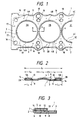
- a metal gasket 1 shown in Fig. 1 is used for sealing opposed fitting surfaces between a cylinder head and a cylinder block in a multiple-cylinder engine such as a 6-cylinder engine.
- the metal gasket 1 consists of a single elastic metal plate or elastic metal plates, and the thickness t of the plate or plates is selected from the range of 0.10 to 0.30 mm in accordance with the structure of the metal gasket. It has been necessary conventionally to use a soft metal material having a hardness Hv of up to 200 before hardening in order to carry out fold-machining but according to the present invention, a material having a hardness Hv of up to 350 can be used for the elastic metal plate 3.
- Holes for combustion chambers 2A, 2B, 2C (which will be hereinafter referred generically to as "holes” and will be represented by reference numeral 2) are formed in the elastic metal plate 3 of the metal gasket 1 corresponding in number to the number of cylinders of the multi-cylinder engine. Oil holes for passing an oil, oil return holes 16, bolt holes 17 of bolts for fastening the metal gasket 1 between opposed fitting surfaces, water holes 18 of cooling water, knock holes, rivet holes, etc., are bored in the elastic metal plate 3 of the metal gasket 1.
- the elastic metal plate 3 has on opposed sides surrounding each hole the shape of a conical mountain and a conical valley around the hole in the section passing through the hole, though the section is not shown in the drawing, so that it seals the periphery of each hole when the metal gasket 1 is fastened.
- a non-metallic material having heat resistance and oil resistance such as a fluoro rubber and resin is applied to both surfaces of the metal gasket 1 to a thickness of about 10 about 50 ⁇ , though this coating is not shown in the drawing. Accordingly, it is possible to avoid metal-to-metal contact between the cylinder head and the cylinder block and to secure sufficient corrosion resistance, durability and strength as the metal gasket. Even if any concavo-convexities exist on the metal gasket 1 itself or on mechanical machining surfaces such as the opposed fitting surfaces between the cylinder head and the cylinder block, the non-metallic material described above can cover the concavo-convexities and can exhibit a sufficient sealing function. Coating by the non-metallic material is preferably completed after the thickness adjustment of the elastic metal plate 3 having the holes formed thereon and before the start of fold-machining.
- Fig. 2 shows the section of the metal gasket 1 cut along a line A - A connecting the centers of the holes 2A and 2B at the boundary portion of the adjacent holes 2 formed in the elastic metal plate 1, that is, the section between the holes 2. This sectional structure holds also true of the boundary portions of other adjacent holes 2.
- the metal gasket 1 consists of a single elastic metal plate 3.
- the thickness t of this elastic metal plate 3 is within the range of about 0.10 to about 0.3 mm, for example, about 0.25 mm.
- Beads 4A, 4B, 4C (all of which will be generically represented by reference numeral 4) having a mountain-shaped sectional shape, that is, having concavo-convexities, are so formed around the holes 2 as to encompass concentrically and annularly the proximity portions of these holes 2.
- the beads 4 merge with one another into one bead 4 in the regions between adjacent holes such as the holes 2A and 23. The distance from each hole 2 becomes progressively smaller at the merging portion of the beads 4, and the width of the beads 4 becomes small as described above.
- the beads 4 may be spaced apart by a small distance from one another without being overlapped with one another.
- the beads 4 start at the position of a distance L 2 (e.g. about 2.0 mm) from the inner periphery of the hole 2, a predetermined width L 3 as viewed in the radial direction is about 2 mm in the region between the holes 2 and is about 2.5 mm in regions other than the regions between the holes 2.
- the top on the convexity side of each bead 4 is formed substantially flat with a width of 5 mm in the regions other than the regions between the holes 2. This arrangement stabilizes the contact between the beads 4 and the opposed fitting surfaces, though a spring constant is somewhat lowered.
- the height H of the beads is about 0.25 mm which is the thickness of the elastic metal plate 3.
- the diameter of the holes 2 is 87 mm, and the distance L 1 between the adjacent holes 2 is about 6.0 mm, for example.
- the elastic metal plate 3 has folded portions 5A, 5B, 5C (all of which will be hereinafter represented generically by reference numeral 5) around the peripheries of the holes 2.
- the folded portions 5 are formed on the convexity side of the beads 4 in such a manner as not to overlap with the beads on the inner side and in the radial direction of the beads 4.
- the width of the folded portions 5 of the elastic metal plate 3 in the radial direction, that is, the folded width L 4 is about 1.5 mm, for example.
- a circumferential groove that is, an annular groove 6 is formed in the region of the folded base portion 7 of the folded portion 11 and the thickness is reduced.
- an annular hollow portion that is, a gap 14, is defined in the folded portion.
- the folded inner surface 12 of the folded portion 11 is in contact with a surface of the elastic metal plate main body, the thickness of which is not reduced, in the region outside the gap 14 in the radial direction of the hole 2.
- the portion 9 of the elastic metal plate main body facing the folded tip 13 of the folded portion 5 is made partially thin from the folded surface side in sucha manner as to define a circumferential groove, that is, an annular groove 8. Accordingly, the folded tip 13 is not in contact with the surface of the elastic metal plate 3.
- the folded portions 5 bear and support the fastening force in cooperation with the beads 4 and prevent compression of the beads 4 by the sheet thickness of the folded portions 5, and thus prevent buckling of the beads 4.
- Deflection of the cylinder head which occurs due to the repetition of the combustion cycles of explosion and expansion strokes of the engine is suppressed by the increase of the ring-like seal portions and by the absorption of irregularity of the opposed fitting surfaces, and the occurrence of cracks in the seal portions can be prevented.
- Such functions of the metal gasket 1 are not different from those of the conventional metal gasket.
- the annular region of the folded portion 5 consisting of the surface 10 coming into contact with the elastic metal plate 3, that is, the elastic metal plate main body, shares and supports the fastening force.
- the folded portion 5 is not pressed to the elastic metal plate main body 3 at the folded base portion 7 having the gap 14 and at the folded free end 13 and even when it comes into contact with the main body, its press force is sufficiently small. Accordingly, the gap 14 of the folded edge 7 is not absorbed by the fastening work of the metal gasket 1 but is maintanined even when fastening is completed. Therefore, the folded base 7 is not crushed and stress concentration does not occur.
- the folded portion 5 serves as an offset to the elastic metal plate main body, but the surface of the elastic metal plate 3 at which the folded free end 13 is positioned has the annular groove 8 due to the reduction of the thickness. Deformation which eliminates such an offset is applied to the elastic metal plate 3 when the metal gasket 1 is clamped between the opposed fitting surfaces, but the elastic metal plate 3 is bendable from the starting position of the thin portion 9 of the annular region positioned inward in the radial direction from the folded free end 13. Therefore, the bending stress occurring in the elastic metal plate main body is reduced at this offset portion.
- the metal gasket 1 has the construction as described above, and can be produced by the production method involving the following steps. This production method will be explained with reference to an exploded view of Fig. 4 showing the elastic metal plate 3 before folding.
- perforations 15 having a radius smaller by a predetermined length than that of desired holes 2 are bored in the elastic metal plate 3.
- Each perforation 15 is a hole which will become the folded free end 13 at the time of completion of folding.
- the center of the hole 2 is in conformity with that of the perforation 15.
- Various holes other than the holes 2 such as the bolt holes 17 are bored.
- the annular grooves 6 and 8 are formed by shaping into a reduced thickness the annular region 7 having a predetermined width L 5 (0.6 mm in the embodiment shown in the drawing) with the portion spaced by a folded width L 4 outward from the periphery of the perforation 15 in the radial direction as the center, and the annular region 9 having a predetermined width L 6 (0.6 mm in the embodiment shown in the drawing) with the portion (spaced by a distance double the folded width L 4 from the perforation 15), at which the folded free end 13 is positioned, as the center, respectively.
- the reduction of the thickness of the elastic metal plate 3 is carried out from the surface of the elastic metal plate 3 on its folded side.
- a region the thickness of which is not reduced is formed between the thin portion 7 of the annular region and the thin portion 9 of the annular region with a predetermined gap (0.5 mm in the embodiment shown in the drawing) between them.
- the depth d of the thin portion is 0.02 mm in the embodiment shown in the drawing.
- the reduction of thickness for forming the annular grooves 6, 8 in the elastic metal plate 3 may be made by any of machining methods inclusive of press shaping, etching, cutting, and so forth.
- press shaping can be carried out simultaneously with punch-out of the perforation 15.
- the beads 4 are formed on the elastic metal plate 3 along the holes 2, and the folded portion 11 having the folded width L 4 up to the center line of the annular groove 6 is bent outward in the radial direction on the side of the surface on which thickness reduction is made, around the perforation 15, so that the surface 12 of the folded portion 11 is brought into contact with the surface 10.
- the folded free end 13 is brought to the center position of the annular groove 8, that is, the annular region the thickness of which is reduced.
- the folded portion 5 using the inner periphery of the folded base 7 thus folded as the hole 2 is formed.
- the elastic metal plate 3 having the folded portion 5 thus formed thereon is heat-treated and hardened, and the metal gasket 1 having suitable elasticity can be produced.
- a step of delicate deformation to a predetermined thickness can be carried out by applying a compressive force to the folded portion 5 in the direction of its thickness.
- the cylinder head has lower rigidity than the cylinder block, and the portions between the adjacent holes 2 in the multiple-cylinder engine are the portions at which the greatest distortion is likely to occur due to the load fluctuation in the combustion cycles of explosion and expansion strokes of the engine. Accordingly, these portions are also the portions at which the sealing function of the metal gasket 1 is most likely to decrease.
- the thickness of the folded portion 5 positioned in the regions between the holes 2 may be made greater than the thickness of the folded portion 5 positioned in the regions other than the regions between the holes 2. Therefore, it is possible to provide a step of applying a compressive force for deforming the folded portion 5 positioned in the regions other than the regions between the holes 2 much more greatly than the folded portion 5 positioned between the holes 2, after the fold-machining step of folding the folded portion 5.
- the thickness is greatest in the region a between the holes 2 of the elastic metal plate 3, progressively decreases in the regions b extending on both sides of the region a and becomes the smallest in the region c extending on both sides of the regions b .
- the elastic metal plate 3 is heat-treated and hardened. At this time, hardening is so made that the hardness is below Hv 350 before the formation of the beads and becomes a hardness in accordance with the kind of the elastic metal plate 3 (e.g. Hv 500) after the heat-treatment.
- the metal gasket shown in Fig. 5 consists of two elastic metal plates.
- This metal gasket 20 comprises an elastic metal plate 3 having the folded portion 5 formed thereon and an elastic metal plate 21 having a thickness greater than that of the first-mentioned elastic metal plate 3 and having the beads 24 formed thereon.
- another elastic metal plate 21 is laminated on the elastic metal plate 3, the beads 24 are formed on the elastic metal plate 21 along the holes 22, and the convexities of the beads 24 are so positioned as to face the folded portion 5 of the elastic metal plate 3.
- the thickness of the elastic metal plate 3 is about 0.12 mm.
- the position of each hole 22 in the elastic metal plate 21 is in complete conformity with the hole 2 of the elastic metal plate 3.
- the folded portion 5 is not functionally different from that of the foregoing embodiment.
- the folded portion 5 of the elastic metal plate 3 is folded and formed towards the beads 24 of the elastic metal plate 21.
- this folded portion 5 shares and supports the fastening force in cooperation with the beads 24, and prevents complete compression of the beads and their buckling.
- the metal gasket shown in Fig. 6 comprises an elastic metal plate 3 having a folded portion 5 formed thereon and another elastic metal plate 31 having a bead 34 formed thereon and having a greater thickness than that of the elastic metal plate 3.
- the other elastic metal plate 31 is laminated on the elastic metal plate 3, the bead 34 is formed along the hole 32 and the convexity of this bead 34 fits into the recess of the bead 4 of the elastic metal plate 3 under the alignment state.
- the elastic metal plate 31 has the same structure as that of the elastic metal plate 21 shown in Fig. 5.
- the elastic metal plate 3 forming the folded portion 5 has the same thickness as that of the elastic metal plate 3 shown in Fig.
- the bead 4 is so formed as to match with the bead shape of the elastic metal plate 31. Accordingly, when both elastic metal plates 3, 31 are superposed, they are in a matching state without any gap between them.
- the folding direction of the folded portion 5 exists on the convexity side of the bead 4, and the basic functions such as bearing and supporting of the fastening force of the metal gasket 30, the prevention of full compression and buckling of the bead, absorption of irregularity of the opposed fitting surfaces, the prevention of cracks due to the load fluctuation during engine operation, and so forth, are the same as those described above.
- the metal gasket 40 shown in Fig. 7 consists of two elastic metal plates, i.e. an elastic metal plate 3 having a folded portion 5 formed thereon and an elastic metal plate 41 having a thickness greater than that of the elastic metal plate 3 and having a bead 44 formed thereon.
- the elastic metal plate 41 has a structure equipped with the bead 44 formed along the hole 42, in the same way as the elastic metal plate 21 shown in Fig. 5 and the elastic metal plate 31 shown in Fig. 6.
- the thickness of the elastic metal plate 3 forming the folded portion 5 is approximately equal to that of the elastic metal plate 3 shown in Fig.
- the elastic metal plate 3 having a smaller thickness first reaches its yielding point at a small force and then the thick elastic metal plate 41 starts deflection and exhibits desirable spring characteristics in accordance with the fastening step.
- the folded portion 5 is folded towards the convexity side of the bead 4, and the basic functions such as sharing and supporting of the fastening force of the metal gasket 40, the prevention of full compression and buckling of the beads 4, 44, absorption of any irregularity of the opposed fitting surfaces, the prevention of cracks due to the load fluctuation during the engine operation, and so forth, are the same as those described above.
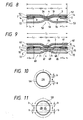
- the metal gasket 50 shown in Fig. 8 consists of three elastic metal plates.
- This metal gasket 50 corresponds to the metal gasket which is obtained by laminating a further elastic metal plate on the metal gasket 30 shown in Fig. 6 in such a manner that their bead portions oppose one another.
- the external elastic plates 51, 55 include beads 54, 56, respectively.
- the beads 54 and 56 are disposed on the sides so that their convexities oppose each other.
- the elastic metal plate 3 forming the folded portion 5 is sandwiched between both elastic metal plates 51 and 55, and is laminated on the elastic metal plate 51 without a gap and with their bead shapes being in conformity with each other in the same way as in the metal gasket 30 shown in Fig. 6.
- the holes 52, 52 and 53, 53 of the elastic metal plates 51, 55 are in conformity with the holes 2, 2 of the elastic metal plate 3.
- the basic functions such as sharing and supporting of the fastening force of the metal gasket 50, the prevention of full compression and buckling of the beads, absorption of irregularity of the opposed fitting surfaces, the prevention of cracks due to the load fluctuation during engine operation, and so forth, are the same as those of the foregoing embodiments.
- the metal gasket 60 shown in Fig. 9 consists of three elastic metal plates.
- the metal gasket 60 has the structure of a laminate type wherein an intermediate plate consisting of two elastic metal plates 3, 68, the tops of the beads 4, 69 of which come into symmetric contact with each other, is sandwiched between two elastic metal plates 61, 65 having the beads 64, 67 so formed thereon as to extend along juxtaposed holes 62, 72.
- An offset portion 71 having a height less than the thickness of the elastic metal plate 3 as a second intermediate plate is formed along the hole 70 of the elastic metal plate 68 as a first intermediate plate, and the elastic metal plate 3 is laminated on the outer surface which becomes a convex surface due to the formation of the offset portion 71.
- the folded portion 5 of the elastic metal plate 3 is folded towards the offset portion 71 formed on the first intermediate plate, and forms a compensation portion having a thickness greater than the sum of the thickness of the two intermediate plates at the portions at which the tops of the beads 4 and 69 come into mutual contact, around the holes 2, 70.
- This compensation portion improves the face-to-face pressure at the time of fastening of the metal gasket between the opposed fitting surfaces, reduces the stress fluctuation of the bead substrate and the bending stress applied thereto, prevents the breakage of the bead portions and compensation portion and the decrease of the sealing effect, and exhibits a stable sealing effect under severe conditions for the metal gasket such as in a diesel engine.
Landscapes
- Engineering & Computer Science (AREA)
- General Engineering & Computer Science (AREA)
- Mechanical Engineering (AREA)
- Gasket Seals (AREA)
Claims (9)
- Joint métallique (1) comprenant une plaque élastique (3) faite d'un matériau métallique et dotée d'orifices (2) pour des chambres de combustion et de portions repliées (5) chacune formée radialement vers l'extérieur par rapport auxdits orifices (2), caractérisé en ce que des premières gorges annulaires (6) sont formées dans les côtés de surface interne desdites portions repliées (5) afin de s'étendre le long desdits orifices (2) et donc de diminuer l'épaisseur de ladite plaque métallique élastique (3), ladite plaque métallique élastique (3) est repliée de manière que des portions creuses annulaires (14) soient formées sur les côtés de surface interne desdites portions repliées (5) par lesdites premières gorges annulaires (6), et des secondes gorges annulaires (8) sont formées dans la surface de ladite plaque métallique élastique (3) en des portions auxquelles des extrémités libres repliées (13) desdites portions repliées (5) sont positionnées de manière à diminuer l'épaisseur desdites portions.
- Joint métallique selon la revendication 1, dans lequel des nervures (4) sont formées sur ladite plaque métallique élastique (3) afin de s'étendre le long desdits orifices (2) et servent de portions d'étanchéité comportant une surface sur le côté desdites portions repliées (5) façonnée en une partie convexe et l'autre surface façonnée en une partie concave.
- Joint métallique selon la revendication 2, comprenant en outre une deuxième plaque métallique élastique (41, 65) laminée sur ladite première plaque métallique élastique (3) sur la partie convexe desdites nervures (4), ladite deuxième plaque métallique élastique (41, 65) comprenant, comme portions d'étanchéité, des nervures (44, 67) comportant une surface façonnée en une partie convexe et l'autre surface façonnée en une partie concave, et lesdites parties convexes de ladite première plaque métallique élastique (3) et lesdites parties convexes de ladite deuxième plaque métallique élastique (41, 65) se font face et sont en contact mutuel.
- Joint métallique selon la revendication 3, comprenant en outre une troisième plaque métallique élastique (68) disposée entre ladite première plaque métallique élastique (3) et ladite deuxième plaque métallique élastique (65).
- Joint métallique selon la revendication 1, comprenant en outre une deuxième plaque métallique élastique (41, 55) comportant des orifices (42, 53) correspondant auxdits orifices (2) dans ladite première plaque métallique élastique (3) laminée sur ladite première plaque métallique élastique (3), ladite deuxième plaque métallique élastique (41, 55) comprenant des nervures (44, 56) formées de manière à s'étendre le long desdits orifices (42, 53) en son sein, lesdites parties convexes desdites nervures (44, 56) de ladite deuxième plaque métallique élastique (41, 55) et lesdites portions repliées (5) de ladite première plaque métallique élastique (3) étant en contact mutuel en face à face.
- Joint métallique selon la revendication 2, comprenant en outre une deuxième plaque métallique élastique (31) comportant des orifices (32) correspondant auxdits orifices (2) dans ladite première plaque métallique élastique (3) laminée sur ladite première plaque métallique élastique (3), ladite deuxième plaque métallique élastique (31) comprenant des nervures (34) formées de manière à s'étendre le long desdits orifices (32) en son sein, et les parties convexes desdites nervures (34) dans ladite deuxième plaque métallique élastique (31) s'emboîtent dans lesdites parties concaves desdites nervures (4) de ladite première plaque métallique élastique (3) en s'épousant.
- Procédé de fabrication d'un joint métallique, comprenant les opérations consistant à produire une plaque métallique élastique (3) à partir d'un matériau métallique ayant une élasticité, former des perforations (15) de petit diamètre dans ladite plaque métallique élastique (3), et replier ladite plaque métallique élastique (3) vers l'extérieur dans une direction radiale depuis la périphérie desdites perforations (15) pour former des portions repliées (5) afin de former des orifices (2) pour des chambres de combustion, caractérisé en ce que le procédé comprend en outre l'opération consistant à usiner des premières et secondes gorges annulaires (6, 8) dans ladite plaque métallique élastique (3), lesdites premières gorges annulaires (6) étant chacune formées dans une région où ladite plaque métallique élastique (3) doit être repliée pour former lesdits orifices (2) et lesdites secondes gorges annulaires (8) étant chacune formées dans une région où les extrémités (13) des portions repliées (5) sont situées lorsque ladite plaque métallique élastique (3) est repliée.
- Procédé de fabrication d'un joint métallique selon la revendication 7, comprenant en outre l'opération consistant à former des nervures (4) comportant des parties convexes sur le côté des portions repliées (5) le long desdits orifices (2).
- Procédé de fabrication d'un joint métallique selon la revendication 7, comprenant en outre l'opération consistant à laminer une deuxième plaque métallique élastique (41) sur ladite première plaque métallique élastique (3), ladite deuxième plaque métallique élastique (41) comportant des orifices (42) correspondant auxdits orifices (2) dans ladite première plaque métallique élastique (3) et des nervures (44) qui s'étendent le long des orifices (42) en son sein.
Applications Claiming Priority (2)
| Application Number | Priority Date | Filing Date | Title |
|---|---|---|---|
| JP252847/91 | 1991-09-05 | ||
| JP3252847A JP2841250B2 (ja) | 1991-09-05 | 1991-09-05 | 金属製ガスケット及びその製造方法 |
Publications (2)
| Publication Number | Publication Date |
|---|---|
| EP0531076A1 EP0531076A1 (fr) | 1993-03-10 |
| EP0531076B1 true EP0531076B1 (fr) | 1996-11-27 |
Family
ID=17243011
Family Applications (1)
| Application Number | Title | Priority Date | Filing Date |
|---|---|---|---|
| EP92307894A Expired - Lifetime EP0531076B1 (fr) | 1991-09-05 | 1992-08-28 | Joint d'étanchéité métallique et son procédé de fabrication |
Country Status (4)
| Country | Link |
|---|---|
| US (1) | US5294135A (fr) |
| EP (1) | EP0531076B1 (fr) |
| JP (1) | JP2841250B2 (fr) |
| DE (2) | DE531076T1 (fr) |
Families Citing this family (36)
| Publication number | Priority date | Publication date | Assignee | Title |
|---|---|---|---|---|
| US5364109A (en) * | 1992-11-13 | 1994-11-15 | Chrysler Corporation | Sealing gasket with hard interior backbone and integral crush limiters |
| JP3197395B2 (ja) * | 1993-01-14 | 2001-08-13 | 日本メタルガスケット株式会社 | 金属ガスケット |
| JP2730478B2 (ja) * | 1994-03-15 | 1998-03-25 | 国産部品工業株式会社 | メタルガスケット |
| JP3250914B2 (ja) * | 1994-09-06 | 2002-01-28 | 日本ガスケット株式会社 | チェーンケース付きエンジン用金属製ガスケット |
| DE9414941U1 (de) * | 1994-09-14 | 1994-11-10 | Reinz-Dichtungs-Gmbh, 89233 Neu-Ulm | Metallische Flachdichtung |
| US5700016A (en) * | 1995-05-31 | 1997-12-23 | Ishikawa Gasket Co., Ltd. | Metal laminate gasket with surface pressure adjustment mechanism |
| DE19520695C1 (de) * | 1995-06-07 | 1996-07-04 | Elringklinger Gmbh | Metallische Zylinderkopfdichtung |
| JP3230959B2 (ja) * | 1995-09-05 | 2001-11-19 | 日本ガスケット株式会社 | 金属ガスケット |
| JPH09105462A (ja) * | 1995-10-09 | 1997-04-22 | Nippon Gasket Co Ltd | 金属製ガスケット |
| US5727795A (en) * | 1996-11-20 | 1998-03-17 | Dana Corporation | Single layer or multi-layer metal cylinder head gasket and method of making the same |
| US6257591B1 (en) | 1996-12-16 | 2001-07-10 | Kokusan Parts Industry Co., Ltd. | Metal gasket and process for manufacturing the same |
| US5988650A (en) * | 1997-07-25 | 1999-11-23 | Dana Corporation | Multi-layered cylinder head gasket with compensating intermediate plate |
| US6209883B1 (en) | 1998-03-04 | 2001-04-03 | Dana Corporation | Single layer head gasket with integral stopper and method of making the same |
| US6092810A (en) * | 1998-03-04 | 2000-07-25 | Dana Corporation | Single layer head gasket with integral stopper |
| JP2000074219A (ja) * | 1998-08-27 | 2000-03-14 | Nippon Gasket Co Ltd | 金属製ガスケット |
| US6318736B1 (en) * | 1999-03-11 | 2001-11-20 | Jet Seal, Inc. | Multiple-ply resilient sealing ring |
| US6357758B1 (en) * | 1999-06-30 | 2002-03-19 | Federal-Mogul World Wide, Inc. | Metal gasket and method of manufacturing |
| JP3756713B2 (ja) * | 1999-10-20 | 2006-03-15 | 日本リークレス工業株式会社 | シリンダーヘッド用メタルガスケット |
| JP4718660B2 (ja) * | 1999-12-15 | 2011-07-06 | 日本ガスケット株式会社 | 金属製ガスケット |
| DE10060514B4 (de) * | 2000-12-06 | 2006-11-30 | Carl Freudenberg Kg | Flachdichtung für eine Kolbenkraft- oder Arbeitsmaschine |
| DE10123486B4 (de) * | 2001-05-15 | 2005-07-28 | Elringklinger Ag | Zylinderkopfdichtung |
| DE10123485B4 (de) * | 2001-05-15 | 2012-12-13 | Elringklinger Ag | Flachdichtung sowie Verfahren zu ihrer Herstellung |
| US6962345B2 (en) * | 2002-02-15 | 2005-11-08 | Dana Corporation | MLS gasket with bore edge stopper bead |
| US6899340B2 (en) | 2002-02-15 | 2005-05-31 | Dana Corporation | MLS gasket with bore edge stopper bead |
| US6951338B2 (en) * | 2003-03-21 | 2005-10-04 | Dana Corporation | Cylinder head gasket |
| US6969072B2 (en) | 2003-04-28 | 2005-11-29 | Dana Corporation | Cylinder head gasket with fold-over stopper |
| US7100925B2 (en) * | 2003-07-31 | 2006-09-05 | Perkin Elmer, Inc. | Pressure energized metallic seal |
| US20050189724A1 (en) * | 2004-02-26 | 2005-09-01 | Federal-Mogul Corporation | Metal gasket |
| DE102004050302B4 (de) * | 2004-10-15 | 2010-09-30 | Norma Germany Gmbh | Verbindung zweier Rohre und Dichtring für die Verbindung |
| DE102005012172B4 (de) * | 2004-11-05 | 2013-03-14 | Federal-Mogul Sealing Systems Gmbh | Flachdichtung |
| CN101798969A (zh) * | 2010-04-01 | 2010-08-11 | 重庆长安汽车股份有限公司 | 一种发动机气缸盖密封垫 |
| US9476382B2 (en) * | 2012-08-10 | 2016-10-25 | Dana Automotive Systems Group, Llc | Multi-layered gasket |
| US9226433B2 (en) | 2013-03-15 | 2015-12-29 | Laird Technologies, Inc. | Selectively conductive EMI gaskets |
| US8884168B2 (en) | 2013-03-15 | 2014-11-11 | Laird Technologies, Inc. | Selectively conductive EMI gaskets |
| US10359003B2 (en) | 2014-06-23 | 2019-07-23 | Tenneco Inc. | Cylinder head gasket with compression limiter and full bead loading |
| US10119494B2 (en) | 2015-07-28 | 2018-11-06 | Tenneco Inc. | Multi-layer gasket assembly |
Family Cites Families (12)
| Publication number | Priority date | Publication date | Assignee | Title |
|---|---|---|---|---|
| US3053544A (en) * | 1958-10-24 | 1962-09-11 | Chrysler Corp | Gasket |
| US4121846A (en) * | 1974-12-20 | 1978-10-24 | Mccord Corporation | Gasket assembly |
| US4213620A (en) * | 1978-12-20 | 1980-07-22 | General Motors Corporation | Cylinder head gasket |
| JPS61232368A (ja) * | 1985-04-05 | 1986-10-16 | Honda Motor Co Ltd | シリンダヘツドガスケツト |
| JPS61255253A (ja) * | 1985-05-09 | 1986-11-12 | Nippon Metal Gasket Kk | 金属ガスケツト |
| JPS63214570A (ja) * | 1987-03-03 | 1988-09-07 | Nippon Reinz Co Ltd | メタルガスケツト |
| DE3869877D1 (de) * | 1987-09-05 | 1992-05-14 | Nihon Metal Gasket | Laminierte metalldichtung. |
| JPH0830538B2 (ja) * | 1990-05-08 | 1996-03-27 | 日本メタルガスケット株式会社 | 金属ガスケット |
| EP0485692A1 (fr) * | 1990-11-14 | 1992-05-20 | Friedhelm Stecher | Procédé de fabrication d'une garniture d'étanchéité plate et outillage pour la mise en oeuvre du procédé |
| JP2930699B2 (ja) * | 1990-11-14 | 1999-08-03 | 日本ガスケット株式会社 | 金属製ガスケット及びその製造方法 |
| DE486255T1 (de) * | 1990-11-14 | 1992-10-15 | Nippon Gasket Co. Ltd., Higashiosaka, Osaka | Metalldichtung und verfahren zur herstellung. |
| JP2989282B2 (ja) * | 1991-01-09 | 1999-12-13 | 日本ガスケット株式会社 | 金属ガスケット |
-
1991
- 1991-09-05 JP JP3252847A patent/JP2841250B2/ja not_active Expired - Fee Related
-
1992
- 1992-08-28 DE DE199292307894T patent/DE531076T1/de active Pending
- 1992-08-28 DE DE69215460T patent/DE69215460T2/de not_active Expired - Fee Related
- 1992-08-28 EP EP92307894A patent/EP0531076B1/fr not_active Expired - Lifetime
- 1992-08-31 US US07/937,093 patent/US5294135A/en not_active Expired - Lifetime
Also Published As
| Publication number | Publication date |
|---|---|
| DE69215460D1 (de) | 1997-01-09 |
| JP2841250B2 (ja) | 1998-12-24 |
| US5294135A (en) | 1994-03-15 |
| DE69215460T2 (de) | 1997-04-30 |
| JPH0565959A (ja) | 1993-03-19 |
| DE531076T1 (de) | 1993-09-02 |
| EP0531076A1 (fr) | 1993-03-10 |
Similar Documents
| Publication | Publication Date | Title |
|---|---|---|
| US5294135A (en) | Metal gasket and production method thereof | |
| EP0533357B1 (fr) | Joint d'étanchéité métallique | |
| JP2844501B2 (ja) | 金属製ガスケットおよびその製造方法 | |
| US6036194A (en) | Combustion gas seal for an internal combustion engine | |
| JPH09105463A (ja) | 金属製ガスケット | |
| KR20040084806A (ko) | 금속 개스킷 | |
| WO1998011365A9 (fr) | Joint d'etancheite pour gaz de combustion utilise dans un moteur a combustion interne | |
| US20030042689A1 (en) | Cylinder head gasket | |
| JP3343478B2 (ja) | 金属製ガスケット | |
| RU2381376C2 (ru) | Уплотнение головки цилиндра | |
| EP1564453A1 (fr) | Joint de culasse | |
| JP2844500B2 (ja) | 金属製ガスケット | |
| EP0845621B1 (fr) | Joint métallique | |
| US20010026047A1 (en) | Laminated gasket | |
| US7108268B2 (en) | Metal laminate gasket | |
| JP2930744B2 (ja) | 金属ガスケット | |
| JP2527102Y2 (ja) | 金属ガスケット | |
| EP0695897A1 (fr) | Joint d'étanchéité métallique pour moteurs munis de chambres de tubulences | |
| JP2895311B2 (ja) | 金属製ガスケットの製造方法 | |
| JPH04181070A (ja) | 金属製ガスケット及びその製造方法 | |
| EP1561976B1 (fr) | Joint de culasse | |
| JP4508667B2 (ja) | シリンダーヘッド用メタルガスケット | |
| US6997462B2 (en) | Cylinder head gasket | |
| JP3086008B2 (ja) | 金属製ガスケット | |
| JPH051730Y2 (fr) |
Legal Events
| Date | Code | Title | Description |
|---|---|---|---|
| PUAI | Public reference made under article 153(3) epc to a published international application that has entered the european phase |
Free format text: ORIGINAL CODE: 0009012 |
|
| AK | Designated contracting states |
Kind code of ref document: A1 Designated state(s): DE GB |
|
| DET | De: translation of patent claims | ||
| 17P | Request for examination filed |
Effective date: 19930909 |
|
| 17Q | First examination report despatched |
Effective date: 19950317 |
|
| GRAG | Despatch of communication of intention to grant |
Free format text: ORIGINAL CODE: EPIDOS AGRA |
|
| GRAH | Despatch of communication of intention to grant a patent |
Free format text: ORIGINAL CODE: EPIDOS IGRA |
|
| GRAH | Despatch of communication of intention to grant a patent |
Free format text: ORIGINAL CODE: EPIDOS IGRA |
|
| GRAA | (expected) grant |
Free format text: ORIGINAL CODE: 0009210 |
|
| AK | Designated contracting states |
Kind code of ref document: B1 Designated state(s): DE GB |
|
| REF | Corresponds to: |
Ref document number: 69215460 Country of ref document: DE Date of ref document: 19970109 |
|
| PLBE | No opposition filed within time limit |
Free format text: ORIGINAL CODE: 0009261 |
|
| STAA | Information on the status of an ep patent application or granted ep patent |
Free format text: STATUS: NO OPPOSITION FILED WITHIN TIME LIMIT |
|
| 26N | No opposition filed | ||
| REG | Reference to a national code |
Ref country code: GB Ref legal event code: IF02 |
|
| PGFP | Annual fee paid to national office [announced via postgrant information from national office to epo] |
Ref country code: GB Payment date: 20060601 Year of fee payment: 15 |
|
| PGFP | Annual fee paid to national office [announced via postgrant information from national office to epo] |
Ref country code: DE Payment date: 20060928 Year of fee payment: 15 |
|
| GBPC | Gb: european patent ceased through non-payment of renewal fee |
Effective date: 20070828 |
|
| PG25 | Lapsed in a contracting state [announced via postgrant information from national office to epo] |
Ref country code: DE Free format text: LAPSE BECAUSE OF NON-PAYMENT OF DUE FEES Effective date: 20080301 |
|
| PG25 | Lapsed in a contracting state [announced via postgrant information from national office to epo] |
Ref country code: GB Free format text: LAPSE BECAUSE OF NON-PAYMENT OF DUE FEES Effective date: 20070828 |