EP0531480B1 - Dispositif pour fixation de ski - Google Patents
Dispositif pour fixation de ski Download PDFInfo
- Publication number
- EP0531480B1 EP0531480B1 EP92906818A EP92906818A EP0531480B1 EP 0531480 B1 EP0531480 B1 EP 0531480B1 EP 92906818 A EP92906818 A EP 92906818A EP 92906818 A EP92906818 A EP 92906818A EP 0531480 B1 EP0531480 B1 EP 0531480B1
- Authority
- EP
- European Patent Office
- Prior art keywords
- vii
- pointer
- housing
- clamp assembly
- front clamp
- Prior art date
- Legal status (The legal status is an assumption and is not a legal conclusion. Google has not performed a legal analysis and makes no representation as to the accuracy of the status listed.)
- Expired - Lifetime
Links
Images


Classifications
-
- A—HUMAN NECESSITIES
- A63—SPORTS; GAMES; AMUSEMENTS
- A63C—SKATES; SKIS; ROLLER SKATES; DESIGN OR LAYOUT OF COURTS, RINKS OR THE LIKE
- A63C9/00—Ski bindings
- A63C9/08—Ski bindings yieldable or self-releasing in the event of an accident, i.e. safety bindings
- A63C9/0805—Adjustment of the toe or heel holders; Indicators therefor
-
- A—HUMAN NECESSITIES
- A63—SPORTS; GAMES; AMUSEMENTS
- A63C—SKATES; SKIS; ROLLER SKATES; DESIGN OR LAYOUT OF COURTS, RINKS OR THE LIKE
- A63C9/00—Ski bindings
- A63C9/08—Ski bindings yieldable or self-releasing in the event of an accident, i.e. safety bindings
- A63C9/085—Ski bindings yieldable or self-releasing in the event of an accident, i.e. safety bindings with sole hold-downs, e.g. swingable
- A63C9/08535—Ski bindings yieldable or self-releasing in the event of an accident, i.e. safety bindings with sole hold-downs, e.g. swingable with a mobile body or base or single jaw
- A63C9/0855—Ski bindings yieldable or self-releasing in the event of an accident, i.e. safety bindings with sole hold-downs, e.g. swingable with a mobile body or base or single jaw pivoting about a vertical axis
-
- A—HUMAN NECESSITIES
- A63—SPORTS; GAMES; AMUSEMENTS
- A63C—SKATES; SKIS; ROLLER SKATES; DESIGN OR LAYOUT OF COURTS, RINKS OR THE LIKE
- A63C9/00—Ski bindings
- A63C9/08—Ski bindings yieldable or self-releasing in the event of an accident, i.e. safety bindings
- A63C9/085—Ski bindings yieldable or self-releasing in the event of an accident, i.e. safety bindings with sole hold-downs, e.g. swingable
- A63C9/08557—Details of the release mechanism
- A63C9/08564—Details of the release mechanism using cam or slide surface
-
- A—HUMAN NECESSITIES
- A63—SPORTS; GAMES; AMUSEMENTS
- A63C—SKATES; SKIS; ROLLER SKATES; DESIGN OR LAYOUT OF COURTS, RINKS OR THE LIKE
- A63C9/00—Ski bindings
- A63C9/001—Anti-friction devices
Definitions
- the invention relates to a device according to the preamble of claim 1.
- Such a front jaw is known from AT-B-387 524 or EP-A-0 331 886.
- the pointer was intended as a mark attached to the sleeve loaded by the release spring, whereas the scale was located on a slide that was firmly connected to the pull rod. In the section of the slide which had the scale, an elongated hole was left open, along which the pointer could move.
- the set value of the setting number was constant, regardless of whether a ski boot was in the ski binding or not.
- a front jaw has also become known which has a housing and a sleeve which can be adjusted relative to it and forms a pointer, the housing being provided with a substantially rectangular recess and in this with a window and having a scale running in the direction of the ski in the region of the recess .
- the sleeve also serves as an abutment for the release spring.
- the tip of the shoe is held by two rigidly connected sole holders (see Salomon catalog 90-91, p.957).
- the entire housing is pivoted about a vertical ski-fixed bolt.
- the trigger spring is acted upon at its end region facing the bolt. Since the sleeve is screwed into the housing, there is no relative movement between these components. Due to this structure of the toe piece, the display device consist of the sleeve acting as a pointer and an inclined scale on the housing.
- AT-PS 338 154 shows another front jaw, in which the scale is not fixed to the housing, but is instead arranged on a movable component.
- the invention has for its object to provide a display device in a toe with a holding system for the ski boot of the type described above, which has the advantages of a scale fixed to the housing. Correct reading of the predetermined setting number should therefore also be made possible in systems in which a relative movement takes place between the sleeve and the scale attached to the housing.
- the reading accuracy of the display device is increased by the measure of claim 2.
- a particularly favorable constructive embodiment of an embodiment of the pointer characterizes the features of claim 3.
- the features of claim 5 enable a positive movement of the pointer along the scale without a separate return spring being required for this.
- the embodiment according to claim 6 has proven to be particularly advantageous.
- the subject matter of claim 7 provides a particularly compact guide for the pointer.
- the pointer is secured against unintentional lifting off its axis.
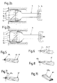
- FIG. 1 is a vertical longitudinal central section through a first embodiment and FIG. 2 is a section along the line II-II in FIG. 1, the pretensioning of the release spring being set to the value 3.
- 2a shows a detail from FIG. 2, the pretensioning of the release spring being set to the value 5 and the ski boot not yet inserted, and FIG. 2a the same detail, but with the ski boot already inserted.
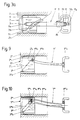
- 3 is a vertical longitudinal central section through a second embodiment.
- FIG. 3a shows a detail of this embodiment in section along the line IIIa-IIIa in FIG. 3, the pretensioning of the release spring being set to the value 6.
- 4 shows a similar detail, in which the preload of the release spring is set to the value 3.
- Figures 5 to 8 and 11 show variants of the design of the pointer end.
- FIGS. 9 and 10 show details of two further embodiments in representations which are similar to FIGS. 2a, 2bb and 3a.
- the ski binding part designed as a toe is designated in its entirety by 1. It has a housing 2, which is provided on its upper side 2a with a rectangular recess 2b. A window 3 made of a transparent plastic is inserted into this recess 2b. A projection 3a of the window 3 engages under one edge of the recess 2b, whereas the opposite side of the window 3 is held by an approximately U-shaped holding part 4 made of an elastic plastic and extending in the transverse direction, by the legs 4a of the holding part designed as hooks 4 snap into corresponding recesses in the housing 2. In the bottom of the window 3, a transverse scale 3b is incised.
- the housing 2 has a bore 2c which extends in the longitudinal direction of the ski and in which a cup-shaped sleeve 5 is displaceably but secured against rotation. These Sleeve 5 forms a spring abutment for a release spring 6. This is screwed onto the threaded section 8a of a pull rod 8. The end of the release spring 6 remote from the sleeve 5 is supported on a wall 2d of the housing 2, which is penetrated by the pull rod 8.
- a design of a toe piece is known per se and is not the subject of the present invention.
- the sleeve 5 carries on its upper side 5a a tongue 5b which extends in the direction of the axis of the release spring 6 and which is delimited by a surface 5c which extends obliquely to the said axis.
- a trigger plate 8b is riveted to the pull rod 8 and has at its upper end an upwardly open recess into which the end of a pointer 9 provided with an annular groove 9a is inserted. This end is overlapped by a projection 13a of a holding part 13 which is fastened to the release plate 8b.
- the pointer 9 is - seen in plan view - approximately T-shaped. On the underside of the pointer 9, a longitudinal groove 9b is recessed, in which the tongue 5b of the sleeve 5 is guided.
- the ski binding part 1 'shown in FIGS. 3, 3a and 4 is similar to that described first. It differs from this primarily in that the pointer 9 'is arranged so that it can pivot about its vertical axis 10' relative to the release plate (8'b) by means of its hub 9'f.
- the pointer 9 '- seen in longitudinal section - has a step, a groove 9'c being cut out in the step surface. This groove 9'c is opposite an abutment 9'd.
- an obliquely extending, cross-sectionally L-shaped guide rib 5'c engages, which on its rear side on the abutment 9'd abuts and which is arranged on the top 5'a of the sleeve 5 '.
- a pentagonal prism 9'e is attached to the free end of the pointer 9 'and serves to display the set value of the spring preload.
- the distance between the pointer 9 'and the window 3' is reduced by the prism 9'e and the reading is thereby improved.
- the embodiment according to FIGS. 3, 3a and 4 is characterized in that the handle 9'f has an extension 9'g diametrically to the pointer 9 ', which is overlapped by a projection 13'a of a holding part 13'.
- the holding part 13 ' is attached to the front wall of the release plate 8'b. Underneath the projection 13'a there is a recess 13'b which makes it possible to pivot the pointer 9 'within a predetermined range.
- the pointers according to FIGS. 5 to 8 can also be used in an advantageous manner.
- the value is indicated by a V-shaped recess 9 ′′ h in the pointer 9 ′′.
- the pointer 9 '''shown in FIG. 6 is indicated by a tip 9''' i.
- the pointer 9 IV of Figure 7 carries at its end a disc 9 IV k, which has a mark 9 IV k 1 in the middle in the form of a hole.
- the pointer 9 V shown in FIG. 8 does not end in a tip, like the pointer 9 ′′, but in a rectangle 9 V m, the long side of which extends in the direction of the pointer axis.
- pointers 9 IV and 9 VII shown in FIGS. 9 and 10 are formed by springs.
- This measure is already known, as the AT-PS 323.619 shows.
- the spring which is curved in the shape of an arc, is attached at one end to a housing in which an adjusting screw for adjusting a release spring is mounted.
- This set screw is wedged with an annular disc, which on its circumference is provided with steps. The spring lies against one of these steps, the free end of which is assigned to a scale fixed to the housing.
- the function is fundamentally different.
- the end of the pointer 9 IV designed as a spiral spring is guided along an inclined surface 5 VI c, which is arranged on the upper side 5 VI a of the sleeve 5 VI .
- the end of the pointer carries a disc 9 VI k, with a mark 9 VI k1.
- the plane of the pointer 9 VII designed as a spiral spring lies parallel to the plane of the scale 3 VII b.
- the pointer 9 VII is rectangular in plan view and has a longitudinally extending recess 9 VII o, so that a frame-like shape is formed.
- a downwardly projecting pin 9 VII n is arranged, which projects into an obliquely running groove 5 VII c of a sleeve 5 VII .
- the end of the pointer 9 VIII shown in FIG. 11 is characterized in that the pointer 9 VIII has a roof-shaped upper side following the pointer end 9 VIII e designed as a prism. This improves the contrast of the pointer 9 VIII relative to the scale.
- the design of the pointer end can also be used in the embodiments according to FIGS. 3, 4, 9 and 10.
- a design of the spring in the embodiment according to FIG. 9 as a bending torsion spring is conceivable.
- the increase in contrast according to FIG. 11 can also be used with good success in other embodiments of pointers.
Landscapes
- Footwear And Its Accessory, Manufacturing Method And Apparatuses (AREA)
- Electric Cable Installation (AREA)
- Suspension Of Electric Lines Or Cables (AREA)
Abstract
Claims (15)
- Mâchoire avant (1) pour fixations de sécurité pour skis, comprenant un boîtier (2, 2', 2VI, 2VII) pouvant être assujetti à la face supérieure d'un ski, et dans lequel un levier coudé respectif est monté sur deux axes s'étendant perpendiculairement à la face supérieure du ski, lesquels leviers coudés (12a, 12b) emprisonnent latéralement, par leurs bras de levier longs, la semelle d'une chaussure de ski engagée, lesdits leviers coudés (12a, 12b) pouvant pivoter en s'opposant à la force d'un ressort de déclenchement (6) prenant appui, d'une part, contre une paroi transversale (2d) du boîtier (2, 2', 2VI, 2VII) et, d'autre part, contre une douille (5, 5', 5IV, 5VII) qui est vissée sur un segment fileté (8a) d'une tige de traction (8) logée dans le boîtier (2, 2', 2VI, 2VII) ; mâchoire dans laquelle le ressort de déclenchement (6) est parcouru centralement par la tige de traction (8) et cette dernière porte, à son extrémité postérieure, une plaque de déclenchement (8b, 8'b, 8VI, 8VII) sollicitant les bras de levier courts des deux leviers coudés (12a, 12b) ; et dans laquelle cette mâchoire avant (1) est pourvue d'une échelle graduée (3b, 3'b, 3VIb, 3VIIb) en vue de l'affichage de l'indice de réglage de la force de déclenchement, et une aiguille (9, 9', 9VI, 9VII) est affectée à l'échelle graduée (3b, 3'b, 3VIb, 3VIIb), caractérisée par le fait que la douille (5, 5', 5IV, 5VII) présente, sur son côté supérieur tourné vers l'échelle graduée (3b, 3'b, 3VIb, 3VIIb) , une surface (5c, 5'c, 5VI, 5VII) s'étendant à l'oblique par rapport à l'axe longitudinal du boîtier (2, 2', 2VI, 2VII) ; par le fait que l'aiguille (9, 9', 9VI, 9VII) est prévue sur la plaque de déclenchement (8b, 8'b, 8VI, 8VII) et est affectée, par son autre région extrême libre éloignée de la plaque de déclenchement (8b, 8'b, 8VI, 8VII) , à la fois à la surface inclinée (5c, 5'c, 5VI, 5VII) de la douille (5, 5', 5IV, 5VII) et à l'échelle graduée (3b, 3'b, 3VIb, 3VIIb) ; et par le fait que l'échelle graduée (3b, 3'b, 3VIb, 3VIIb) est directement disposée sur une fenêtre (3, 3', 3VI, 3VII) du boîtier (2, 2', 2VI, 2VII) et s'étend, d'une manière connue en soi, dans le sens transversal du ski.
- Mâchoire avant selon la revendication 1, caractérisée par le fait que l'aiguille (9) est d'une réalisation de type coulisseau et d'une configuration sensiblement en T observée en plan et forme, avec la surface inclinée (5c) de la douille (5), par son bord extrême (9j) éloigné de la plaque de déclenchement (8b) et s'étendant transversalement par rapport à l'axe longitudinal du boîtier (2), un point d'intersection dans l'échelle graduée (3b) qui correspond à l'indice de réglage considéré.
- Mâchoire avant selon la revendication 1 ou 2, caractérisée par le fait que l'aiguille (9) est guidée par sa région extrême affectée à l'échelle graduée (3b) , au moyen d'une gorge longitudinale (9b) s'étendant à sa face inférieure, sur une languette (5b) de la douille (5) qui s'étend axialement, et est ancrée à la plaque de déclenchement (8b) par son extrémité tournée à l'opposé de l'échelle graduée (3b).
- Mâchoire avant selon la revendication 3, caractérisée par le fait que l'aiguille (9) est ancrée à la plaque de déclenchement (8b) au moyen d'une gorge annulaire (9a) qui est engagée dans un évidement (8c), ouvert vers le haut, de la plaque de déclenchement (8b), et est coiffée par une protubérance (13a) d'une pièce de retenue (13) disposée sur la plaque de déclenchement (8b) et assujettie à cette plaque de déclenchement (8b).
- Mâchoire avant selon la revendication 1, caractérisée par le fait que l'aiguille (9') peut pivoter par rapport à la plaque de déclenchement (8'b) à l'aide de son moyeu (9'f), autour de l'axe vertical (10') de ce dernier ; et par le fait que la région extrême de l'aiguille (9') qui est affectée à l'échelle graduée (3'b) présente, à sa face inférieure, une gorge (9'c) dans laquelle est guidée une nervure de guidage (5'c) de la douille (5'), munie de la surface s'étendant à l'oblique (figures 3 et 4).
- Mâchoire avant selon la revendication 5, caractérisée par le fait que la nervure de guidage (5'c) de la douille (5') possède une section transversale configurée en L.
- Mâchoire avant selon la revendication 5 ou 6, caractérisée par le fait que l'aiguille (9') comporte, à sa face inférieure, un gradin (9'm) dans la surface duquel la gorge (9'c) est pratiquée ; et par le fait qu'une contrebutée (9'd), saillant vers le bas et destinée à la nervure de guidage (5'c), est située sur l'aiguille (9') en vis-à-vis de la gorge (9'c).
- Mâchoire avant selon la revendication 7, caractérisée par le fait qu'un prisme (9'e) saillant vers le haut est fixé à la région extrême libre de l'aiguille (9'), prisme dont l'un des bords se trouve dans le plan médian longitudinal vertical de l'aiguille (9') (figure 11).
- Mâchoire avant selon la revendication 5, caractérisée par le fait que l'aiguille (9') présente, sur son moyeu (9'f), un appendice (9'g) coiffé par une protubérance (13'a) d'une pièce de retenue (13') prévue sur la plaque de déclenchement (8'b) (figure 3).
- Mâchoire avant selon la revendication 5, caractérisée par le fait que l'aiguille (9'') possède, dans sa région extrême libre, une échancrure (9''h) configurée en V (figure 5).
- Mâchoire avant selon la revendication 5, caractérisée par le fait que l'aiguille (9VI) porte, dans sa région extrême libre, un disque (9IVk) présentant, en son centre, un repère (9IVk₁) revêtant, par exemple, la forme d'un trou (figure 7).
- Mâchoire avant selon la revendication 1, caractérisée par le fait que l'aiguille (9VI) réalisée, de manière connue en soi, sous la forme d'un ressort de flexion prend appui, par sa région extrême libre, contre la surface (5VIc) de la douille (5VI) qui s'étend à l'oblique par rapport à l'axe longitudinal du boîtier (2IV) (figure 9).
- Mâchoire avant selon la revendication 12, caractérisée par le fait que l'aiguille (9VI) porte, dans sa région extrême libre, un disque (9VIk) muni d'un repère (9VIk₁) dont le point d'intersection avec l'échelle graduée (3IVb) correspond à l'indice de réglage considéré (figure 9).
- Mâchoire avant selon la revendication 1, caractérisée par le fait que l'aiguille (9VII) rectangulaire observée en plan, réalisée de manière connue sous la forme d'un ressort, comporte un évidement rectangulaire (9VIIo) s'étendant dans sa direction longitudinale ; et par le fait qu'un tenon (9VIIn), situé sur le côté étroit de l'aiguille (9VII) qui est affecté à l'échelle graduée (3VIIb), fait saillie vers le bas dans une gorge (5VIIc) de la douille (5VII), s'étendant à l'oblique par rapport à l'axe longitudinal du boîtier (2VII), laquelle gorge (5VIIc) présente la surface s'étendant à l'oblique (figure 10).
- Mâchoire avant selon la revendication 1, caractérisée par le fait que la face supérieure de la région extrême libre de l'aiguille (9VIII) est réalisée en forme de toiture ; et par le fait que cette région extrême comporte un repère orienté en direction de la plaque de déclenchement et revêtant la forme d'un prisme (9VIIIe) triangulaire observé en plan (figure 11).
Applications Claiming Priority (3)
| Application Number | Priority Date | Filing Date | Title |
|---|---|---|---|
| AT685/91 | 1991-03-28 | ||
| AT0068591A AT395823B (de) | 1991-03-28 | 1991-03-28 | Vorrichtung fuer einen skibindungsteil |
| PCT/EP1992/000655 WO1992017249A1 (fr) | 1991-03-28 | 1992-03-25 | Dispositif pour fixation de ski |
Publications (2)
| Publication Number | Publication Date |
|---|---|
| EP0531480A1 EP0531480A1 (fr) | 1993-03-17 |
| EP0531480B1 true EP0531480B1 (fr) | 1994-11-23 |
Family
ID=3497114
Family Applications (1)
| Application Number | Title | Priority Date | Filing Date |
|---|---|---|---|
| EP92906818A Expired - Lifetime EP0531480B1 (fr) | 1991-03-28 | 1992-03-25 | Dispositif pour fixation de ski |
Country Status (7)
| Country | Link |
|---|---|
| US (1) | US5333892A (fr) |
| EP (1) | EP0531480B1 (fr) |
| JP (1) | JPH074439B2 (fr) |
| AT (1) | AT395823B (fr) |
| CA (1) | CA2078857A1 (fr) |
| DE (1) | DE59200806D1 (fr) |
| WO (1) | WO1992017249A1 (fr) |
Families Citing this family (12)
| Publication number | Priority date | Publication date | Assignee | Title |
|---|---|---|---|---|
| FR2689773B1 (fr) * | 1992-04-10 | 1994-06-10 | Salomon Sa | Dispositif indicateur de la precontrainte appliquee notamment au ressort de rappel d'un element de fixation alpine. |
| FR2722374B1 (fr) * | 1994-07-13 | 1996-09-27 | Salomon Sa Societe Anonyme | Ensemble d'une chaussure et d'un element de retenue, noramment pour la pratique du ski |
| US5690351A (en) * | 1995-07-21 | 1997-11-25 | Karol; Chris | Snowboard binding system |
| WO1997014479A1 (fr) * | 1995-10-19 | 1997-04-24 | Erwin Weigl | Fixation de ski |
| DE69815558T2 (de) * | 1997-01-29 | 2004-04-29 | Look Fixations S.A. | Sicherheitsbindung an der Oberseite des Skistiefels |
| FR2759603B1 (fr) * | 1997-02-20 | 1999-04-23 | Look Fixations Sa | Fixation de securite de l'extremite avant d'une chaussure |
| FR2765114B1 (fr) * | 1997-06-26 | 1999-09-03 | Look Fixations Sa | Fixation de securite de chaussure de ski |
| ITTV20010150A1 (it) * | 2001-11-13 | 2003-05-13 | Benetton Spa | Dispositivo di visualizzazione della posizione di un componente particolarmente per una talloniera e/o un puntale di un attacco di sci |
| US8212158B2 (en) * | 2009-04-13 | 2012-07-03 | Wiest Pieter C | Weight measuring shoe having a retractable scale |
| US10105587B2 (en) * | 2012-04-12 | 2018-10-23 | William L. Cyr | Free heel touring-style ski binding slip differential cassette |
| US10058763B2 (en) * | 2015-04-29 | 2018-08-28 | Bishop Bindings Llc | Telemark ski bindings systems and methods |
| US11229831B2 (en) | 2018-06-24 | 2022-01-25 | Bishop Bindings Llc | Telemark ski binding assembly |
Family Cites Families (14)
| Publication number | Priority date | Publication date | Assignee | Title |
|---|---|---|---|---|
| FR2234019A2 (en) * | 1963-08-22 | 1975-01-17 | Gertsch Ag | Tension indicator for adjustable ski safety binding - straight ended spring in contact with adjusting mechanism |
| AT323619B (de) * | 1973-06-19 | 1975-07-25 | Smolka & Co Wiener Metall | Einrichtung zum einstellen und anzeigen der gegenseitigen lage von unter federwirkung stehenden skibindungsteilen |
| AT338154B (de) * | 1974-11-18 | 1977-07-25 | Ver Baubeschlag Gretsch Co | Skibindungselement |
| DE2558339C3 (de) * | 1975-12-23 | 1980-09-11 | Vereinigte Baubeschlagfabriken Gretsch & Co Gmbh, 7250 Leonberg | Sicherheitsvorderbacken |
| AT343027B (de) * | 1976-04-14 | 1978-05-10 | Smolka & Co Wiener Metall | Skibindungsteil |
| AT351423B (de) * | 1977-04-27 | 1979-07-25 | Smolka & Co Wiener Metall | Federverrastung |
| DE3337993A1 (de) * | 1983-10-19 | 1985-05-09 | Geze Gmbh, 7250 Leonberg | Sicherheitsvorderbacken einer skibindung |
| FR2554358B1 (fr) * | 1983-11-08 | 1986-07-18 | Look Sa | Butee-avant de securite pour ski |
| DE3605313C2 (de) * | 1986-02-19 | 1994-12-08 | Geze Sport | Seitenauslösbare Sicherheitsskibindung |
| DE3720440A1 (de) * | 1987-06-19 | 1989-01-05 | Geze Sport | Seitenausloesbarer vorderbacken einer sicherheitsskibindung |
| AT387524B (de) * | 1987-08-11 | 1989-02-10 | Tyrolia Freizeitgeraete | Vorderbacken fuer sicherheitsskibindungen |
| AT389820B (de) * | 1988-03-10 | 1990-02-12 | Tyrolia Freizeitgeraete | Vorderbacken fuer sicherheitsskibindungen |
| AT390382B (de) * | 1988-05-04 | 1990-04-25 | Tyrolia Freizeitgeraete | Vorderbacken fuer sicherheitsskibindungen |
| FR2632537B1 (fr) * | 1988-06-08 | 1991-12-06 | Salomon Sa | Fixation de securite pour ski |
-
1991
- 1991-03-28 AT AT0068591A patent/AT395823B/de not_active IP Right Cessation
-
1992
- 1992-03-25 WO PCT/EP1992/000655 patent/WO1992017249A1/fr not_active Ceased
- 1992-03-25 US US07/952,847 patent/US5333892A/en not_active Expired - Fee Related
- 1992-03-25 JP JP4506524A patent/JPH074439B2/ja not_active Expired - Lifetime
- 1992-03-25 DE DE59200806T patent/DE59200806D1/de not_active Expired - Fee Related
- 1992-03-25 EP EP92906818A patent/EP0531480B1/fr not_active Expired - Lifetime
- 1992-03-25 CA CA002078857A patent/CA2078857A1/fr not_active Abandoned
Also Published As
| Publication number | Publication date |
|---|---|
| ATA68591A (de) | 1992-08-15 |
| WO1992017249A1 (fr) | 1992-10-15 |
| JPH05505970A (ja) | 1993-09-02 |
| JPH074439B2 (ja) | 1995-01-25 |
| DE59200806D1 (de) | 1995-01-05 |
| EP0531480A1 (fr) | 1993-03-17 |
| US5333892A (en) | 1994-08-02 |
| CA2078857A1 (fr) | 1992-09-29 |
| AT395823B (de) | 1993-03-25 |
Similar Documents
| Publication | Publication Date | Title |
|---|---|---|
| EP0531480B1 (fr) | Dispositif pour fixation de ski | |
| WO1988004562A1 (fr) | Systeme de reglage pour fixations de ski | |
| WO1990011806A1 (fr) | Fixation pour skis de fond ou de randonnee | |
| DE3143576C2 (de) | Backen, insbesondere Vorderbacken, für Sicherheitsskibindungen | |
| DE3415272C2 (fr) | ||
| AT402794B (de) | Skibindung mit einer arretiervorrichtung für vorder- und/oder fersenbacken | |
| DE1578858A1 (de) | Vorderbacken fuer Sicherheits-Skibindungen | |
| EP0345371B1 (fr) | Fixation avant de sécurité pour le ski | |
| DE3143974C2 (de) | Fersenhalter für eine Sicherheitsskibindung | |
| EP0303026B1 (fr) | Mâchoire avant pour fixation de ski de sécurité | |
| EP0189562B1 (fr) | Talonnière pour fixation de ski | |
| DE2107376A1 (de) | Verstell und Anzeigeeinrichtung | |
| DE2705661C2 (de) | Fersenhalter für Skibindungen | |
| EP0700311B1 (fr) | Dispositif de fixation de ski servant a fixer une chaussure de ski sur un ski, notamment un ski de randonnee ou ski de fond | |
| DE1956653A1 (de) | Vorderbacken fuer Sicherheits-Skibindungen | |
| DE2550459C3 (de) | Lageranordnung für den Drehteller des Fersenbackens einer auslösenden Skibindung | |
| DE69801128T2 (de) | Vorderbacken einer Sicherheitsskibindung | |
| DE2157791C3 (de) | Sicherheitsskibindung | |
| DE3124853A1 (de) | Backen, insbesondere vorderbacken fuer sicherheitsskibindungen | |
| EP0432407A2 (fr) | Fixation de sécurité pour ski avec une partie réglable | |
| EP0119518B1 (fr) | Fixation de sécurité pour ski | |
| DE3612696A1 (de) | Vorderbacken | |
| DE2603959A1 (de) | Ausloeseskibindung | |
| DE1801880B2 (de) | Federverrastung für Sicherheitsskibindungen | |
| AT394143B (de) | Sicherheits-vorderbacken fuer skibindungen |
Legal Events
| Date | Code | Title | Description |
|---|---|---|---|
| PUAI | Public reference made under article 153(3) epc to a published international application that has entered the european phase |
Free format text: ORIGINAL CODE: 0009012 |
|
| 17P | Request for examination filed |
Effective date: 19921007 |
|
| AK | Designated contracting states |
Kind code of ref document: A1 Designated state(s): CH DE FR LI |
|
| RAP1 | Party data changed (applicant data changed or rights of an application transferred) |
Owner name: HTM SPORT- UND FREIZEITGERAETE AKTIENGESELLSCHAFT |
|
| 17Q | First examination report despatched |
Effective date: 19940330 |
|
| GRAA | (expected) grant |
Free format text: ORIGINAL CODE: 0009210 |
|
| AK | Designated contracting states |
Kind code of ref document: B1 Designated state(s): CH DE FR LI |
|
| REF | Corresponds to: |
Ref document number: 59200806 Country of ref document: DE Date of ref document: 19950105 |
|
| ET | Fr: translation filed | ||
| PLBE | No opposition filed within time limit |
Free format text: ORIGINAL CODE: 0009261 |
|
| 26N | No opposition filed | ||
| PGFP | Annual fee paid to national office [announced via postgrant information from national office to epo] |
Ref country code: FR Payment date: 19960115 Year of fee payment: 5 |
|
| PGFP | Annual fee paid to national office [announced via postgrant information from national office to epo] |
Ref country code: DE Payment date: 19960116 Year of fee payment: 5 |
|
| PGFP | Annual fee paid to national office [announced via postgrant information from national office to epo] |
Ref country code: CH Payment date: 19960402 Year of fee payment: 5 |
|
| PG25 | Lapsed in a contracting state [announced via postgrant information from national office to epo] |
Ref country code: LI Effective date: 19970331 Ref country code: CH Effective date: 19970331 |
|
| REG | Reference to a national code |
Ref country code: CH Ref legal event code: PL |
|
| PG25 | Lapsed in a contracting state [announced via postgrant information from national office to epo] |
Ref country code: FR Free format text: LAPSE BECAUSE OF NON-PAYMENT OF DUE FEES Effective date: 19971128 |
|
| PG25 | Lapsed in a contracting state [announced via postgrant information from national office to epo] |
Ref country code: DE Effective date: 19971202 |
|
| REG | Reference to a national code |
Ref country code: FR Ref legal event code: ST |