EP0531682A2 - Vorrichtung zum Verschweissen von Profilen aus Kunststoff - Google Patents
Vorrichtung zum Verschweissen von Profilen aus Kunststoff Download PDFInfo
- Publication number
- EP0531682A2 EP0531682A2 EP92112659A EP92112659A EP0531682A2 EP 0531682 A2 EP0531682 A2 EP 0531682A2 EP 92112659 A EP92112659 A EP 92112659A EP 92112659 A EP92112659 A EP 92112659A EP 0531682 A2 EP0531682 A2 EP 0531682A2
- Authority
- EP
- European Patent Office
- Prior art keywords
- profiles
- unit
- counter
- welding
- adjustable
- Prior art date
- Legal status (The legal status is an assumption and is not a legal conclusion. Google has not performed a legal analysis and makes no representation as to the accuracy of the status listed.)
- Granted
Links
Images


Classifications
-
- B—PERFORMING OPERATIONS; TRANSPORTING
- B29—WORKING OF PLASTICS; WORKING OF SUBSTANCES IN A PLASTIC STATE IN GENERAL
- B29C—SHAPING OR JOINING OF PLASTICS; SHAPING OF MATERIAL IN A PLASTIC STATE, NOT OTHERWISE PROVIDED FOR; AFTER-TREATMENT OF THE SHAPED PRODUCTS, e.g. REPAIRING
- B29C37/00—Component parts, details, accessories or auxiliary operations, not covered by group B29C33/00 or B29C35/00
- B29C37/02—Deburring or deflashing
- B29C37/04—Deburring or deflashing of welded articles, e.g. deburring or deflashing in combination with welding
-
- B—PERFORMING OPERATIONS; TRANSPORTING
- B29—WORKING OF PLASTICS; WORKING OF SUBSTANCES IN A PLASTIC STATE IN GENERAL
- B29C—SHAPING OR JOINING OF PLASTICS; SHAPING OF MATERIAL IN A PLASTIC STATE, NOT OTHERWISE PROVIDED FOR; AFTER-TREATMENT OF THE SHAPED PRODUCTS, e.g. REPAIRING
- B29C65/00—Joining or sealing of preformed parts, e.g. welding of plastics materials; Apparatus therefor
- B29C65/02—Joining or sealing of preformed parts, e.g. welding of plastics materials; Apparatus therefor by heating, with or without pressure
- B29C65/18—Joining or sealing of preformed parts, e.g. welding of plastics materials; Apparatus therefor by heating, with or without pressure using heated tools
- B29C65/20—Joining or sealing of preformed parts, e.g. welding of plastics materials; Apparatus therefor by heating, with or without pressure using heated tools with direct contact, e.g. using "mirror"
- B29C65/2007—Joining or sealing of preformed parts, e.g. welding of plastics materials; Apparatus therefor by heating, with or without pressure using heated tools with direct contact, e.g. using "mirror" characterised by the type of welding mirror
- B29C65/203—Joining or sealing of preformed parts, e.g. welding of plastics materials; Apparatus therefor by heating, with or without pressure using heated tools with direct contact, e.g. using "mirror" characterised by the type of welding mirror being several single mirrors, e.g. not mounted on the same tool
-
- B—PERFORMING OPERATIONS; TRANSPORTING
- B29—WORKING OF PLASTICS; WORKING OF SUBSTANCES IN A PLASTIC STATE IN GENERAL
- B29C—SHAPING OR JOINING OF PLASTICS; SHAPING OF MATERIAL IN A PLASTIC STATE, NOT OTHERWISE PROVIDED FOR; AFTER-TREATMENT OF THE SHAPED PRODUCTS, e.g. REPAIRING
- B29C65/00—Joining or sealing of preformed parts, e.g. welding of plastics materials; Apparatus therefor
- B29C65/02—Joining or sealing of preformed parts, e.g. welding of plastics materials; Apparatus therefor by heating, with or without pressure
- B29C65/18—Joining or sealing of preformed parts, e.g. welding of plastics materials; Apparatus therefor by heating, with or without pressure using heated tools
- B29C65/20—Joining or sealing of preformed parts, e.g. welding of plastics materials; Apparatus therefor by heating, with or without pressure using heated tools with direct contact, e.g. using "mirror"
- B29C65/2053—Joining or sealing of preformed parts, e.g. welding of plastics materials; Apparatus therefor by heating, with or without pressure using heated tools with direct contact, e.g. using "mirror" characterised by special ways of bringing the welding mirrors into position
- B29C65/2061—Joining or sealing of preformed parts, e.g. welding of plastics materials; Apparatus therefor by heating, with or without pressure using heated tools with direct contact, e.g. using "mirror" characterised by special ways of bringing the welding mirrors into position by sliding
-
- B—PERFORMING OPERATIONS; TRANSPORTING
- B29—WORKING OF PLASTICS; WORKING OF SUBSTANCES IN A PLASTIC STATE IN GENERAL
- B29C—SHAPING OR JOINING OF PLASTICS; SHAPING OF MATERIAL IN A PLASTIC STATE, NOT OTHERWISE PROVIDED FOR; AFTER-TREATMENT OF THE SHAPED PRODUCTS, e.g. REPAIRING
- B29C65/00—Joining or sealing of preformed parts, e.g. welding of plastics materials; Apparatus therefor
- B29C65/78—Means for handling the parts to be joined, e.g. for making containers or hollow articles, e.g. means for handling sheets, plates, web-like materials, tubular articles, hollow articles or elements to be joined therewith; Means for discharging the joined articles from the joining apparatus
- B29C65/7841—Holding or clamping means for handling purposes
-
- B—PERFORMING OPERATIONS; TRANSPORTING
- B29—WORKING OF PLASTICS; WORKING OF SUBSTANCES IN A PLASTIC STATE IN GENERAL
- B29C—SHAPING OR JOINING OF PLASTICS; SHAPING OF MATERIAL IN A PLASTIC STATE, NOT OTHERWISE PROVIDED FOR; AFTER-TREATMENT OF THE SHAPED PRODUCTS, e.g. REPAIRING
- B29C66/00—General aspects of processes or apparatus for joining preformed parts
- B29C66/01—General aspects dealing with the joint area or with the area to be joined
- B29C66/05—Particular design of joint configurations
- B29C66/10—Particular design of joint configurations particular design of the joint cross-sections
- B29C66/11—Joint cross-sections comprising a single joint-segment, i.e. one of the parts to be joined comprising a single joint-segment in the joint cross-section
- B29C66/116—Single bevelled joints, i.e. one of the parts to be joined being bevelled in the joint area
- B29C66/1162—Single bevel to bevel joints, e.g. mitre joints
-
- B—PERFORMING OPERATIONS; TRANSPORTING
- B29—WORKING OF PLASTICS; WORKING OF SUBSTANCES IN A PLASTIC STATE IN GENERAL
- B29C—SHAPING OR JOINING OF PLASTICS; SHAPING OF MATERIAL IN A PLASTIC STATE, NOT OTHERWISE PROVIDED FOR; AFTER-TREATMENT OF THE SHAPED PRODUCTS, e.g. REPAIRING
- B29C66/00—General aspects of processes or apparatus for joining preformed parts
- B29C66/50—General aspects of joining tubular articles; General aspects of joining long products, i.e. bars or profiled elements; General aspects of joining single elements to tubular articles, hollow articles or bars; General aspects of joining several hollow-preforms to form hollow or tubular articles
- B29C66/51—Joining tubular articles, profiled elements or bars; Joining single elements to tubular articles, hollow articles or bars; Joining several hollow-preforms to form hollow or tubular articles
- B29C66/52—Joining tubular articles, bars or profiled elements
- B29C66/524—Joining profiled elements
- B29C66/5243—Joining profiled elements for forming corner connections, e.g. for making window frames or V-shaped pieces
- B29C66/52431—Joining profiled elements for forming corner connections, e.g. for making window frames or V-shaped pieces with a right angle, e.g. for making L-shaped pieces
-
- B—PERFORMING OPERATIONS; TRANSPORTING
- B29—WORKING OF PLASTICS; WORKING OF SUBSTANCES IN A PLASTIC STATE IN GENERAL
- B29C—SHAPING OR JOINING OF PLASTICS; SHAPING OF MATERIAL IN A PLASTIC STATE, NOT OTHERWISE PROVIDED FOR; AFTER-TREATMENT OF THE SHAPED PRODUCTS, e.g. REPAIRING
- B29C66/00—General aspects of processes or apparatus for joining preformed parts
- B29C66/80—General aspects of machine operations or constructions and parts thereof
- B29C66/84—Specific machine types or machines suitable for specific applications
- B29C66/843—Machines for making separate joints at the same time in different planes; Machines for making separate joints at the same time mounted in parallel or in series
-
- B—PERFORMING OPERATIONS; TRANSPORTING
- B29—WORKING OF PLASTICS; WORKING OF SUBSTANCES IN A PLASTIC STATE IN GENERAL
- B29L—INDEXING SCHEME ASSOCIATED WITH SUBCLASS B29C, RELATING TO PARTICULAR ARTICLES
- B29L2031/00—Other particular articles
- B29L2031/001—Profiled members, e.g. beams, sections
- B29L2031/003—Profiled members, e.g. beams, sections having a profiled transverse cross-section
- B29L2031/005—Profiled members, e.g. beams, sections having a profiled transverse cross-section for making window frames
Definitions
- the invention relates to a device for welding profiles made of plastic, in particular for window frames.
- Window frames made of plastic profiles are known.
- the plastic profiles are extruded as hollow profiles and mitred. They are then welded together to form the frame. It is known to weld such plastic profiles using an automatic device.
- the known devices have four welding units, two of which are each on one of two in parallel Unit carriers are arranged.
- the unit carriers have guides on which at least one welding unit can be adjusted.
- An assembly carrier is normally designed as a slide and can be adjusted relative to the other assembly carrier with the help of machine-fixed guides. The adjustment of the units and the unit carrier is carried out in a known, conventional manner.
- Each welding unit has two supports for the profiles to be inserted by hand as well as two counter profiles and two pressure plates.
- a set consisting of counter profile, support and pressure plate per unit is arranged on a feed slide for the purpose of adjustment relative to the other set. With the help of the pressure plates, a profile is set in the welding unit so that it can be pressed against the other profile under pressure.
- the support and pressure plate each have knife edges. They laterally limit the bulge that results when welding the plastic profiles. However, only horizontal knife edges are provided for bead limitation. Bumps that result in the outer corner areas can not be limited in the known device. The beads are cut off and ground in a subsequent machining process. For this process it is from Extraordinary advantage if there is a perfect bead limitation.
- the invention is therefore based on the object to provide a device for welding profiles made of plastic, in particular for window frames, with which a more extensive limitation of the weld beads can be made possible without the risk of the beads being torn off when the profiles are removed. Furthermore, welding of sealing lips to the profiles should be feasible.
- the device according to the invention has two feed carriages per unit with mutually perpendicular ones Adjustment axes. In this way, it is possible to bring the knife edges very close together, even for an inner outer region of the profiles, during joining and welding, so that a strongly constricted, defined bead is formed.
- the carriages Before the frame is removed from the aggregates, the carriages can be brought into a position in which the supports, the counter profiles and the pressure plates are separated by a certain amount using the aggregates and the aggregate carrier.
- the knife edges have released the beads, so that the beads are not torn off by a knife edge or the entire welding is impaired.
- a sealing lip is attached to the profiles on the outside
- the counter profiles have a limiting groove for a sealing lip attached to the profiles, which is shaped to match the cross section of the sealing lip in a support section at the front end of the counter profile, whereby a receiving groove adjoins the limiting groove, in which the sealing lip can be freely received.
- each counter profile is adjustable, the profiles can be inserted in a position relative to the counter profile in that the sealing lip initially into the receiving groove of the counter profile immersed.
- the counter profile is adjacent to the limiting groove so that a perfect bead formation takes place when the sealing lip ends are welded Knife edges.
- the counter profile can have further, in particular also vertical or knife edges deviating from the horizontal, so that a perfect bead limitation takes place in otherwise inaccessible areas.
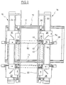
- the device shown in Figures 1 to 3 has a base frame 10 which has two parallel spaced guides 12, 14.
- An assembly carrier 16 is arranged stationary on the frame 10. It can be adjusted, for example, on the guides 12, 14, but does not have its own drive for this and is also fixed using suitable means.
- a second assembly carrier 18 can be moved on the guides 12, 14 perpendicular to the first assembly carrier 16. The drive for this is not shown.
- Two welding units 20, 22 are arranged on the first unit carrier, of which the welding unit 20 can be adjusted along guides 24 relative to the second unit 22.
- the adjustment drive for this is also not shown.
- Two further welding units 26, 28 are arranged on the second unit carrier 18.
- the welding unit 28 is stationary, while the welding unit 26 is adjustable along guides 30 relative to the stationary unit 28.
- the structure of the welding units 20, 22, 26, 28 is the same.
- each carriage 32 or 34 has a support 40 or 42 and a counter profile 44 or 46, on or against which the ends of the profiles are placed, which are indicated by dash-dotted lines, for example at 50.
- pressure plates (not shown) which can be adjusted vertically with the aid of adjusting cylinders in order to press the profiles 50 against the supports 40, 42.
- the welding unit 26 also has a centering element 52, which can be adjusted in height with the aid of an adjusting drive, not shown.
- a elongated heating element 54 is provided on the welding unit, which can be adjusted in the direction of the double arrow with the aid of an adjustment drive, not shown.
- the counter profiles 44, 46 are shown in more detail in FIGS. In the following, only the counter profile 46 is to be treated, since both are of the same design.
- the counter profile 46 has an upper contact surface 56 which is placed on the underside of the profile 50. Furthermore, it has a lateral contact surface 58 arranged perpendicular thereto.
- a recess or receiving groove 60 merges with the front end of the counter profile 46 into a limiting groove 62.
- the bearing surface 56 is widened in the area of the limiting groove 62 in a section 64 up to approximately the lateral limiting surface 58. As can be seen from FIG. 5, it extends Limiting groove 62 at an angle to the vertical.
- knife edge On both sides of the limiting groove 62 is a knife edge at the front end of the counter profile 46, as shown at 66. In addition, knife edges are located at 68 and 70, ie below the support surface 64, as indicated by the dashed line in FIG. 4, for example.
- pressure plates 72, 74 are indicated, which are also provided with knife edges 76, 78, as are the supports 40, 42, as shown at 80, 82.
- the described device works as follows.
- the units 20, 22, 26, 28 and the carriages 32, 34 of the units enter a predetermined position, which is achieved, for example, by numerical control of the drives. This position is shown in FIGS. 1 and 4.
- the counter profiles 44, 46 project beyond the ends of the inserted profiles 50 to a certain extent, for example 30 to 35 mm. If the profiles have an externally attached sealing lip, it is ensured in any case that the sealing lip is at a distance from the laying section 64 and dips into the receiving groove 58 (FIG. 4).
- the assembly carrier 18 and the assemblies 20, 26 are then adjusted in the direction of the arrows, the profiles 50 resting against the centering stop 52 that has been moved upward, and the counter profiles shifting relative to the profiles 50.
- a sealing lip arranged on the profiles dips into the limiting groove of the counter profiles, as was described in connection with FIG. 4.
- the end position of the counter profiles is specified by the numerical control. It is such that the ends of the plastic profiles to be welded protrude a few millimeters above the counter profile and the support or over the lower and upper knife edge. This overlap corresponds to the subsequent burn-up when the profiles to be welded are heated.
- each carriage 32, 34 After the profiles 50 are centered in this way, the pressure plates of each carriage 32, 34 are lowered in order to fix the profiles on the units. Subsequently, with the aid of the adjusting cylinders, the carriages 32, 34 are slightly separated from one another, so that the centering member 52 can move into the lowered position, as indicated by the arrow in FIG. 6. The elongated heating element 54 then moves into the gap, whereupon the slides 32, 34 start moving again and the ends of the profiles to be welded move against the heating element 54. The heating element is floating across its longitudinal extension so that it can effectively engage both ends.
- the profiles are pressed against the heating element with a predetermined pressure, a path measurement (not shown) stopping the feed when a predetermined path has been covered, for example in the order of magnitude that 2 mm of erosion have been reached.
- the carriages 32, 34 then move apart somewhat so that the heating elements 54 can be removed.
- the slides 32, 34 then move the profiles 50 against one another again in order to join them together. This is shown in Fig. 2.
- the profiles are pressed against each other at a predetermined higher pressure and allowed to cool. After cooling, the clamping plates depressurized and the units moved into a first removal position, as shown in Fig. 3.
- the assembly carrier 18 and the welding units 20, 26 are adjusted in the direction of the arrows until the counter profiles 44, 46 and the associated supports and clamping plates have reached the position shown in FIG. 3. All welding beads are released in this, including the welding bead of the sealing lips welded together.
- the adjusting cylinders 36, 38 of the units are also depressurized so that they can yield in the adjustment described. The movement carried out here is indicated by the dashed arrows. Now the clamping plates can be raised so that the frame formed from the profiles 50 can in turn be raised. This lifting mechanism is not shown.
- the adjusting cylinders 36, 38 then move the assigned carriages 32, 34 into a position such that the frame can be placed on two conveyor belts 90 so that it is transported away. This completes a frame and the manufacturing cycle can begin again.
Landscapes
- Engineering & Computer Science (AREA)
- Mechanical Engineering (AREA)
- Physics & Mathematics (AREA)
- Thermal Sciences (AREA)
- Lining Or Joining Of Plastics Or The Like (AREA)
- Arc Welding In General (AREA)
Abstract
Description
- Die Erfindung bezieht sich auf eine Vorrichtung zum Verschweißen von Profilen aus Kunststoff, insbesondere für Fensterrahmen.
- Fensterrahmen aus Kunststoffprofilen sind bekannt. Die Kunststoffprofile werden als Hohlprofile im Strangpreßverfahren hergestellt und auf Gehrung geschnitten. Sie werden anschließend zur Bildung des Rahmens miteinander verschweißt. Es ist bekannt, derartige Kunststoffprofile mit Hilfe einer automatischen Vorrichtung zu verschweißen. Die bekannten Vorrichtungen weisen vier Schweißaggregate auf, von denen jeweils zwei auf einem von zwei parallelen Aggregatträgern angeordnet sind. Die Aggregatträger weisen Führungen auf, auf denen mindestens ein Schweißaggregat verstellt werden kann. Ein Aggregatträger ist normalerweise als Schlitten ausgeführt und kann mit Hilfe von maschinenfesten Führungen relativ zum anderen Aggregatträger verstellt werden. Die Verstellung der Aggregate und des Aggregatträgers erfolgt in bekannter herkömmlicher Weise.
- Jedes Schweißaggregat weist zwei Auflagen für die von Hand einzulegenden Profile auf sowie zwei Konterprofile und zwei Druckplatten. Ein aus Konterprofil, Auflager und Druckplatte bestehender Satz je Aggregat ist auf einem Vorschubschlitten angeordnet, zwecks Verstellung relativ zum anderen Satz. Mit Hilfe der Druckplatten wird ein Profil im Schweißaggregat festgelegt, damit es unter Druck gegen das andere Profil gepreßt werden kann.
- Auflage und Druckplatte haben jeweils Messerkanten. Sie begrenzen seitlich den Wulst, der sich beim Schweißen der Kunststoffprofile ergibt. Es sind jedoch nur horizontale Messerkanten zur Wulstbegrenzung vorgesehen. Wülste, die sich in den äußeren Eckbereichen ergeben, können bei der bekannten Vorrichtung nicht begrenzt werden. Die Wülste werden in einem nachfolgenden Bearbeitungsvorgang abgestochen und abgeschliffen. Für diesen Vorgang ist es von außerordentlichem Vorteil, wenn eine einwandfreie Wulstbegrenzung stattgefunden hat.
- Es ist bekannt, die beschriebenen Fensterprofile mit einer Dichtlippe zu versehen, die in geeigneter Weise an das Profil angeformt wird, beispielsweise durch Verklebung. Beim Verschweißen der Dichtlippen bilden diese einen undefinierten relativ harten Wulst, der die Dichtwirkung beeinträchtigt.
- Der Erfindung liegt daher die Aufgabe zugrunde, eine Vorrichtung zum Verschweißen von Profilen aus Kunststoff, insbesondere für Fensterrahmen, zu schaffen, mit der sich eine weiterreichende Begrenzung der Schweißwülste ermöglichen läßt ohne die Gefahr des Abreißens der Wülste beim Entfernen der Profile. Ferner soll ein Verschweißen von Dichtlippen an den Profilen in einwandfreier Weise durchführbar sein.
- Diese Aufgabe wird gelöst durch die Merkmale des Anspruchs 1.
- Die erfindungsgemäße Vorrichtung weist pro Aggregat zwei Vorschubschlitten auf mit senkrecht aufeinanderstehenden Verstellachsen. Auf diese Weise ist es möglich, die Messerkanten, auch für einen innenliegenden äußeren Bereich der Profile, während des Fügens und des Schweißens sehr nahe zusammenzubringen, so daß ein stark eingeschnürter definierter Wulst gebildet ist. Bevor der Rahmen aus den Aggregaten entfernt wird, kann mit Hilfe der Aggregate und des Aggregatträgers können die Schlitten in eine Stellung gebracht werden, in der die Auflagen, die Konterprofile und die Druckplatten um einen gewissen Betrag voneinander entfernt sind. Bei dem anschließenden Herausheben der Rahmen haben die Messerkanten die Wülste freigegeben, so daß die Wülste nicht durch eine Messerkante abgerissen werden oder die gesamte Verschweißung beeinträchtigt wird.
- Ist an den Profilen eine Dichtlippe außen angebracht, sieht eine Ausgestaltung der Erfindung vor, daß die Konterprofile eine Begrenzungsnut für eine an den Profilen angebrachte Dichtlippe aufweisen, die an den Querschnitt der Dichtlippe angepaßt in einem Auflageabschnitt am vorderen Ende des Konterprofils geformt ist, wobei sich an die Begrenzungsnut eine Aufnahmenut anschließt, in der die Dichtlippe frei aufnehmbar ist. Dadurch, daß erfindungsgemäß jedes Konterprofil verstellbar ist, können die Profile in einer Relativlage zu dem Konterprofil eingelegt werden, daß die Dichtlippe zunächst in die Aufnahmenut des Konterprofils eintaucht. Anschließend erfolgt eine Relativverstellung der Konterprofile zu den eingelegten Kunststoffprofilen, wobei die Dichtlippe in die Begrenzungsnut einläuft, bis die Konterprofile und die Kunststoffprofile ihre Bearbeitungsposition erreicht haben, in der die Kunststoffprofile nur geringfügig über die freien Enden der Konterprofile überstehen. Der Überstand berücksichtigt den sogenannten Abbrand beim Erweichen der zu verschweißenden Enden der Profile mit Hilfe eines Heizelements. Haben die Konterprofile und die Kunststoffprofile die richtige Bearbeitungsposition zueinander, werden die Kunststoffprofile mit Hilfe der Druckplatten festgelegt. Die Festlegung findet jedoch erst statt, nachdem eine Zentrierung erfolgt ist, d.h. die Enden der Kunststoffprofile relativ zu einem Zentrierelement die richtige Position eingenommen haben. Nach dem Zusammenfügen und Verschweißen können die Schlitten, wie oben bereits beschrieben, in eine Position im Abstand zu den Enden bzw. der Ecke des gebildeten Rahmens verfahren werden, bevor der Rahmen bei gelösten Druckplatten angehoben und auf ein Transportband abgelegt wird.
- Damit eine einwandfreie Wulstbildung beim Verschweißen der Dichtlippenenden stattfindet, weist nach einer Ausgestaltung der Erfindung das Konterprofil angrenzend an die Begrenzungsnut Messerkanten auf. Das Konterprofil kann weitere, insbesondere auch vertikale oder von der Horizontalen abweichende Messerkanten aufweisen, damit in sonst unzugänglichen Bereichen eine einwandfreie Wulstbegrenzung stattfindet.
- Die Erfindung wird nachfolgend anhand von Zeichnungen näher erläutert.
- Fig. 1
- zeigt die Draufsicht auf eine schematisch dargestellte Vorrichtung nach der Erfindung in der Einlegeposition.
- Fig. 2
- zeigt die Vorrichtung nach Fig. 1 in der Fügeposition.
- Fig. 3
- zeigt die Vorrichtung nach Fig. 1 in der Entnahmeposition.
- Fig. 4
- zeigt eine Draufsicht auf eine Einzelheit der Vorrichtung nach den Figuren 1 und 3.
- Fig. 5
- zeigt die Frontansicht eines Konterprofils der Darstellung nach Fig. 4 in Richtung Pfeil 5.
- Fig. 6
- zeigt die Ansicht der Einzelheit nach Fig. 4 in Richtung Pfeil 6.
- Die in den Figuren 1 bis 3 dargestellte Vorrichtung weist einen Grundrahmen 10 auf, der zwei parallel beabstandete Führungen 12, 14 aufweist. Auf dem Rahmen 10 ist stationär ein Aggregatträger 16 angeordnet. Er kann zum Beispiel auf den Führungen 12, 14 verstellt werden, hat jedoch hierfür keinen eigenen Antrieb und wird außerdem mit Hilfe geeigneter Mittel festgesetzt. Ein zweiter Aggregatträger 18 kann auf den Führungen 12, 14 senkrecht zum ersten Aggregatträger 16 verfahren werden. Der Antrieb hierfür ist nicht dargestellt.
- Auf dem ersten Aggregatträger sind zwei Schweißaggregate 20, 22 angeordnet, von denen das Schweißaggregat 20 entlang von Führungen 24 gegenüber dem zweiten Aggregat 22 verstellbar ist. Der Verstellantrieb hierfür ist ebenfalls nicht dargestellt. Zwei weitere Schweißaggregate 26, 28 sind auf dem zweiten Aggregatträger 18 angeordnet. Das Schweißaggregat 28 ist stationär, während das Schweißaggregat 26 entlang von Führungen 30 gegenüber dem stationären Aggregat 28 verstellbar ist.
- Der Aufbau der Schweißaggregate 20, 22, 26, 28 ist gleich.
- Daher soll bei den weiteren Betrachtungen lediglich das Schweißaggregat 26 berücksichtigt werden. Es weist zwei Schlitten 32, 34 auf, die mit Hilfe von Verstellzylindern 36, 38 entlang aufeinander senkrecht stehender Achsen verstellbar sind. Jeder Schlitten 32 bzw. 34 weist eine Auflage 40 bzw. 42 und ein Konterprofil 44 bzw. 46 auf, auf die bzw. gegen die die Enden der Profile gelegt werden, die strichpunktiert zum Beispiel bei 50 angedeutet sind. Oberhalb im Abstand zu den Auflagen 40, 42 bzw. den Konterprofilen 44, 46 sind (nicht gezeigte) Druckplatten angeordnet, die mit Hilfe von Verstellzylindern vertikal verstellbar sind, um die Profile 50 gegen die Auflagen 40, 42 anzupressen.
- Das Schweißaggregat 26 weist ferner ein Zentrierelement 52 auf, das mit Hilfe eines nicht gezeigten Verstellantriebs in der Höhe verstellt werden kann. Schließlich ist am Schweißaggregat ein längliches Heizelement 54 vorgesehen, das mit Hilfe eines nicht gezeigten Verstellantriebs in Richtung des Doppelpfeils verstellbar ist.
- In den Figuren 4 und 5 sind die Konterprofile 44, 46 näher dargestellt. Nachfolgend soll lediglich das Konterprofil 46 behandelt werden, da beide gleich ausgebildet sind. Das Konterprofil 46 weist eine obere Auflagefläche 56 auf, auf die die Unterseite des Profils 50 aufgelegt wird. Ferner weist es eine senkrecht dazu angeordnete seitliche Anlagefläche 58 auf. Eine Vertiefung oder Aufnahmenut 60 geht zum vorderen Ende des Konterprofils 46 über in eine Begrenzungsnut 62. Die Auflagefläche 56 ist im Bereich der Begrenzungsnut 62 in einem Abschnitt 64 verbreitert bis annähernd zur seitlichen Begrenzungsfläche 58. Wie aus Fig. 5 zu erkennen, erstreckt sich die Begrenzungsnut 62 im Winkel zur Vertikalen. Sie ist in ihrem Querschnitt und ihrer Lage so geformt,daß sie eine am Profil 50 angeformte Dichtlippe passen aufnimmt, ohne diese zu verformen. Beidseits der Begrenzungsnut 62 ist an dem vorderen Ende des Konterprofils 46 eine Messerkante, wie bei 66 dargestellt. Außerdem befinden sich Messerkanten bei 68 und 70, d.h. unterhalb der Auflagefläche 64, wie zum Beispiel in Fig. 4 durch die gestrichelte Linie angedeutet.
- Bei der Darstellung in Fig. 6 sind Druckplatten 72, 74 angedeutet, die ebenfalls mit Messerkanten 76, 78 versehen sind, wie auch die Auflagen 40, 42, wie bei 80, 82 dargestellt.
- Die beschriebene Vorrichtung arbeitet wie folgt.
- Für eine gegebene Abmessung der Profile 50 nehmen Aggregatträger 18, die Aggregate 20, 22, 26, 28 sowie die Schlitten 32, 34 der Aggregate eine vorgegebene Stellung ein, die zum Beispiel über eine numerische Steuerung der Antriebe erreicht wird. Diese Position ist in Fig. 1 und Fig. 4 dargestellt. In dieser stehen die Konterprofile 44, 46 über die Enden der eingelegten Profile 50 ein gewisses Maß über, zum Beispiel 30 bis 35 mm. Falls die Profile eine außen angebrachte Dichtlippe aufweisen, ist auf jeden Fall sichergestellt, daß die Dichtlippe im Abstand zum Auflegeabschnitt 64 liegt und in die Aufnahmenut 58 eintaucht (Fig. 4). Nach dem Einlegen der Profile 50 werden dann der Aggregatträger 18 und die Aggregate 20, 26 in Richtung der Pfeile verstellt, wobei sich die Profile 50 gegen den nach oben gefahrenen Zentrieranschlag 52 anlegen und sich die Konterprofile relativ zu den Profilen 50 verschieben. Dabei taucht eine an den Profilen angeordnete Dichtlippe in die Begrenzungsnut der Konterprofile, wie in Verbindung mit Fig. 4 beschrieben wurde. Die Endstellung der Konterprofile wird durch die numerische Steuerung vorgegeben. Sie ist derart, daß die Enden der zu verschweißenden Kunststoffprofile einige Millimeter über das Konterprofil und die Auflage bzw. über die untere und obere Messerkante überstehen. Dieser überstand entspricht dem späteren Abbrand beim Erwärmen der zu verschweißenden Profile.
- Nachdem auf diese Weise die Profile 50 zentriert sind, werden die Druckplatten jedes Schlittens 32, 34 abgesenkt zwecks Festlegung der Profile auf den Aggregaten. Anschließend werden mit Hilfe der Verstellzylinder die Schlitten 32, 34 etwas voneinander entfernt, so daß das Zentrierglied 52 in die abgesenkte Stellung fahren kann, wie durch Pfeil in Fig. 6 angedeutet. Anschließend fährt das längliche Heizelement 54 in den Spalt, worauf sich die Schlitten 32, 34 erneut in Bewegung setzen und die Enden der zu verschweißenden Profile gegen das Heizelement 54 fahren. Das Heizelement ist dabei quer zu seiner Längserstreckung schwimmend gelagert, so daß es wirksam mit beiden Enden in Eingriff treten kann. Die Profile werden mit einem vorgegebenen Druck gegen das Heizelement angepreßt, wobei eine nicht gezeigte Wegmessung den Vorschub stoppt, wenn ein vorgegebener Weg zurückgelegt wurde, beispielsweise in einer Größenordnung, daß 2 mm Abbrand erreicht sind. Anschließend fahren die Schlitten 32, 34 wieder etwas auseinander, so daß die Heizelemente 54 entfernt werden können. Daraufhin fahren die Schlitten 32, 34 die Profile 50 wieder gegeneinander, um sie aneinanderzufügen. Dies ist in Fig. 2 dargestellt. Die Profile werden mit einem vorgegebenen höheren Druck gegeneinandergepreßt und erkalten gelassen. Nach dem Erkalten werden die Spannplatten drucklos gemacht und die Aggregate in eine erste Entnahmeposition gefahren, wie dies in Fig. 3 dargestellt ist.
- Bei drucklos geschalteten Spannplatten werden der Aggregatträger 18 und die Schweißaggregate 20, 26 in Richtung der Pfeile verstellt, bis die Konterprofile 44, 46 und die zugehörigen Auflagen und Spannplatten die in Fig. 3 gezeigte Position erreicht haben. In dieser sind alle Schweißwülste freigegeben, auch der Schweißwulst der miteinander verschweißten Dichtlippen. Bei dieser Verstellung versteht sich, daß auch die Verstellzylinder 36, 38 der Aggregate drucklos geschaltet sind, damit sie bei der beschriebenen Verstellung nachgeben können. Die hierbei durchgeführte Bewegung ist durch die gestrichelten Pfeile angedeutet. Nunmehr können die Spannplatten angehoben werden, damit der aus den Profilen 50 gebildete Rahmen seinerseits angehoben werden kann. Dieser Anhebemechanismus ist nicht dargestellt. Anschließend fahren die Verstellzylinder 36, 38 die zugeordneten Schlitten 32, 34 in eine Position, daß der Rahmen auf zwei Förderbändern 90 abgelegt werden kann, damit es abtransportiert wird. Damit ist ein Rahmen fertiggestellt und der Fertigungszyklus kann erneut beginnen.
Claims (6)
- Vorrichtung zum Verschweißen von Profilen aus Kunststoff, insbesondere für Fensterrahmen, mit vier Schweißaggregaten, von denen jeweils zwei auf einem von zwei parallelen Aggregatträgern angeordnet sind, wobei jeweils ein Aggregat eines Paares relativ zum anderen auf dem Aggregatträger verstellbar ist und ein Aggregatträger relativ zum anderen Aggregatträger verstellbar ist, wobei ferner jedes Aggregat zwei Auflagen, zwei Konterprofile und zwei Druckplatten für die Enden der jeweils eingelegten Profile aufweist, die mittels eines Vorschubschlittens relativ zueinander verstellbar sind und die Auflagen, Konterprofile und Druckplatten Messerkanten aufweisen für die Schweißwulstbegrenzung, einem verstellbaren Zentrieranschlag und einem verstellbaren Heizelement an jedem Aggregat, dadurch gekennzeichnet, daß jedes Aggregat (20, 22, 26, 28) zwei Vorschubschlitten (32, 34) mit senkrecht aufeinanderstehenden Verstellachsen aufweist.
- Vorrichtung nach Anspruch 1, dadurch gekennzeichnet, daß die Konterprofile (44, 46) eine Begrenzungsnut (62) für eine an den Profilen (50) angebrachte Dichtlippe aufweisen, die an den Querschnitt der Dichtlippe angepaßt in einem Auflageabschnitt (64) am vorderen Ende der Konterprofile (44, 46) geformt ist, wobei sich an die Begrenzungsnut (62) eine Aufnahmenut (60) anschließt, in der die Dichtlippe frei aufnehmbar ist.
- Vorrichtung nach Anspruch 2, dadurch gekennzeichnet, daß das Konterprofil (44, 46) angrenzend an die Begrenzungsnut (62) auch horizontale Messerkanten (66, 70) aufweist.
- Vorrichtung nach einem der Ansprüche 1 bis 3, dadurch gekennzeichnet, daß die Konterprofile auch horizontale bzw. von der Vertikalen abweichende Messerkanten aufweisen.
- Vorrichtung nach einem der Ansprüche 2 bis 4, dadurch gekennzeichnet, daß die Vorschubschlitten (20, 22, 26, 28) in der Einlegeposition für die Profile (50) einen Überstand über das zugeordnete Profilende aufweisen, der mindestens der Länge der Begrenzungsnut (62) entspricht.
- Vorrichtung nach einem der Ansprüche 2 bis 4, dadurch gekennzeichnet, daß die Vorschubschlitten (20, 22, 26, 28) in der Entnahmeposition für die Profile (50) einen merklichen Abstand von dem Profilende aufweisen.
Applications Claiming Priority (2)
| Application Number | Priority Date | Filing Date | Title |
|---|---|---|---|
| DE9111121U DE9111121U1 (de) | 1991-09-07 | 1991-09-07 | Vorrichtung zum Verschweißen von Profilen aus Kunststoff |
| DE9111121U | 1991-09-07 |
Publications (3)
| Publication Number | Publication Date |
|---|---|
| EP0531682A2 true EP0531682A2 (de) | 1993-03-17 |
| EP0531682A3 EP0531682A3 (en) | 1993-09-01 |
| EP0531682B1 EP0531682B1 (de) | 1997-04-23 |
Family
ID=6871027
Family Applications (1)
| Application Number | Title | Priority Date | Filing Date |
|---|---|---|---|
| EP92112659A Expired - Lifetime EP0531682B1 (de) | 1991-09-07 | 1992-07-24 | Vorrichtung zum Verschweissen von Profilen aus Kunststoff |
Country Status (3)
| Country | Link |
|---|---|
| EP (1) | EP0531682B1 (de) |
| AT (1) | ATE152037T1 (de) |
| DE (2) | DE9111121U1 (de) |
Cited By (4)
| Publication number | Priority date | Publication date | Assignee | Title |
|---|---|---|---|---|
| WO2001012420A1 (de) * | 1999-08-12 | 2001-02-22 | Exama Maschinen Gmbh | Mehrkopf-reibschweissverfahren |
| DE10014163A1 (de) * | 2000-03-23 | 2001-09-27 | Urban Gmbh & Co Maschb Kg | Vorrichtung zum Verschweißen von Kunststoffprofilstäben |
| EP2255942A1 (de) | 2009-05-28 | 2010-12-01 | Murat Makina Sanayi ve Ticaret Ltd. Sti. | Profilschweiß- und -entgratungsverfahren |
| PL132107U1 (pl) * | 2024-04-19 | 2025-10-20 | Kaban Makina Sanayi Ve Ticaret Limited Sirketi | Urządzenie zgrzewające do profili z PCW |
Families Citing this family (4)
| Publication number | Priority date | Publication date | Assignee | Title |
|---|---|---|---|---|
| DE9209471U1 (de) * | 1992-07-15 | 1992-12-10 | Kommanditgesellschaft Hassomat Maschinenbau GmbH & Co., 2000 Hamburg | T-Verbindung aus Profilen aus Kunststoff, insbesondere für Fensterrahmen |
| AU4904896A (en) * | 1995-01-27 | 1996-08-14 | Andersen Corporation | Vibratory welded window and door joints, method and apparatus for manufacturing the same |
| DE19506236B4 (de) * | 1995-02-23 | 2006-06-29 | Afs Federhenn Maschinen Gmbh | Verfahren zum Verschweißen von vier Kunststoffprofilen |
| DE19832397C2 (de) * | 1998-07-18 | 2003-05-22 | Afs Holding Gmbh | Verfahren und Vorrichtung zum Beschicken einer m-Kopf-Schweissmaschine |
Family Cites Families (4)
| Publication number | Priority date | Publication date | Assignee | Title |
|---|---|---|---|---|
| GB1255497A (en) * | 1968-05-27 | 1971-12-01 | Pilkington Brothers Ltd | Glass compositions |
| DE2123939A1 (en) * | 1971-05-14 | 1972-11-23 | Frevel, Ernst, 5158 Horrem | Butt welding plastic profiles - with simultaneous removal of outstanding beading |
| DE2201656B2 (de) * | 1972-01-14 | 1980-11-20 | 6780 Pirmasens | Verfahren zum Verschweißen von Kunststoffprofilen und Vorrichtung zur Durchführung des Verfahrens |
| DE3131551C2 (de) * | 1981-08-08 | 1983-06-30 | P. Schulte-Stemmerk KG für Industrie und Handel, 4100 Duisburg | Abdichtung für Fenster- und Türrahmen von Bauwerken |
-
1991
- 1991-09-07 DE DE9111121U patent/DE9111121U1/de not_active Expired - Lifetime
-
1992
- 1992-07-24 AT AT92112659T patent/ATE152037T1/de not_active IP Right Cessation
- 1992-07-24 DE DE59208379T patent/DE59208379D1/de not_active Expired - Fee Related
- 1992-07-24 EP EP92112659A patent/EP0531682B1/de not_active Expired - Lifetime
Cited By (4)
| Publication number | Priority date | Publication date | Assignee | Title |
|---|---|---|---|---|
| WO2001012420A1 (de) * | 1999-08-12 | 2001-02-22 | Exama Maschinen Gmbh | Mehrkopf-reibschweissverfahren |
| DE10014163A1 (de) * | 2000-03-23 | 2001-09-27 | Urban Gmbh & Co Maschb Kg | Vorrichtung zum Verschweißen von Kunststoffprofilstäben |
| EP2255942A1 (de) | 2009-05-28 | 2010-12-01 | Murat Makina Sanayi ve Ticaret Ltd. Sti. | Profilschweiß- und -entgratungsverfahren |
| PL132107U1 (pl) * | 2024-04-19 | 2025-10-20 | Kaban Makina Sanayi Ve Ticaret Limited Sirketi | Urządzenie zgrzewające do profili z PCW |
Also Published As
| Publication number | Publication date |
|---|---|
| EP0531682B1 (de) | 1997-04-23 |
| DE9111121U1 (de) | 1991-10-24 |
| ATE152037T1 (de) | 1997-05-15 |
| EP0531682A3 (en) | 1993-09-01 |
| DE59208379D1 (de) | 1997-05-28 |
Similar Documents
| Publication | Publication Date | Title |
|---|---|---|
| DE69019170T2 (de) | Vorgeschlitzte Injektionsstelle sowie konische Kanüle. | |
| DE3876209T2 (de) | Spannvorrichtung zum schweissen von gehrungsverbindungen zwischen teilen von aus kunststoff geformten fenster- oder tuerrahmen. | |
| EP0674086B2 (de) | Verfahren zum Zusammenbauen von Isolierglasscheiben, deren Innenraum mit einem Schwergas gefüllt ist und Vorrichtung zum Füllen von Isolierglasscheiben mit Schwergas | |
| DE102015107121B4 (de) | Verfahren und Vorrichtung zum Verbinden von Profilteilen | |
| AT403350B (de) | Biegemaschine zum herstellen eines abstandhaltenden innenrahmens für eine isolierglasscheibe | |
| DE2923769A1 (de) | Verfahren und vorrichtung zur herstellung von scheiben fuer verglasung | |
| EP0531682B1 (de) | Vorrichtung zum Verschweissen von Profilen aus Kunststoff | |
| DE2341435A1 (de) | Verfahren und vorrichtung zum rahmen von diapositiven, sowie diaraehmchen zur durchfuehrung des verfahrens | |
| DE9317104U1 (de) | Vorrichtung zum Verschweißen von Folienrändern | |
| DE3529303A1 (de) | Glasplattenschleifmaschine | |
| DE1964572A1 (de) | Filmschneidevorrichtung | |
| EP0685319A2 (de) | Verfahren und Vorrichtung zur Herstellung von rechteckigen Rahmen | |
| EP0531681A2 (de) | Vorrichtung zum Verschweissen von Profilen aus Kunststoff | |
| DE69020170T4 (de) | Apparat zum beschichten der oberfläche und der seitenkanten einer platte aus holz oder ähnlichem material mit einer wärmeverformbaren folie. | |
| DE60107370T2 (de) | Vorrichtung zur Herstellung einer Schaumstoffplatte mit Einlegeteilen | |
| DE2035308A1 (de) | Verfahren und Vorrichtung zur Her stellung von stumpfgeschweißten Rahmen aus Kunststoff oder Leichtmetall Profilschienen | |
| DE102007025157A1 (de) | Maschine zum Herstellen von Teilen aus Holz oder dergleichen | |
| DE3002713A1 (de) | Verfahren und vorrichtung zum verschweissen von profilen aus thermoplastischen kunststoff | |
| DE69023011T2 (de) | Apparat zum beschichten einer oberfläche und der seitenkanten einer holzplatte oder ähnlichen materials mit einer wärmeverformbaren folie. | |
| DE69102519T2 (de) | Biegemaschine. | |
| DE4416634C2 (de) | Verfahren und Vorrichtung zur Herstellung von rechteckigen Rahmen | |
| DE4130085C2 (de) | Verfahren und Vorrichtung zum Bearbeiten von Schweißraupen oder dergleichen an den Ecken eines Rahmens | |
| EP1136233B1 (de) | Vorrichtung zum Verschweissen von Kunststoffprofilstäben | |
| DE2163731A1 (de) | Vorrichtung zur rollnahtdichtschweissung der seitenraender von plattenradiatoren | |
| EP1177991A2 (de) | Verfahren zum Transport und zur Vorbereitung von hohlen Profilstäben aus Kunststoff für die Bildung von Fensterrahmen |
Legal Events
| Date | Code | Title | Description |
|---|---|---|---|
| PUAI | Public reference made under article 153(3) epc to a published international application that has entered the european phase |
Free format text: ORIGINAL CODE: 0009012 |
|
| AK | Designated contracting states |
Kind code of ref document: A2 Designated state(s): AT BE DE FR GB IT |
|
| PUAL | Search report despatched |
Free format text: ORIGINAL CODE: 0009013 |
|
| AK | Designated contracting states |
Kind code of ref document: A3 Designated state(s): AT BE DE FR GB IT |
|
| 17P | Request for examination filed |
Effective date: 19940216 |
|
| 17Q | First examination report despatched |
Effective date: 19950510 |
|
| GRAG | Despatch of communication of intention to grant |
Free format text: ORIGINAL CODE: EPIDOS AGRA |
|
| GRAH | Despatch of communication of intention to grant a patent |
Free format text: ORIGINAL CODE: EPIDOS IGRA |
|
| GRAH | Despatch of communication of intention to grant a patent |
Free format text: ORIGINAL CODE: EPIDOS IGRA |
|
| GRAA | (expected) grant |
Free format text: ORIGINAL CODE: 0009210 |
|
| AK | Designated contracting states |
Kind code of ref document: B1 Designated state(s): AT BE DE FR GB IT |
|
| REF | Corresponds to: |
Ref document number: 152037 Country of ref document: AT Date of ref document: 19970515 Kind code of ref document: T |
|
| REF | Corresponds to: |
Ref document number: 59208379 Country of ref document: DE Date of ref document: 19970528 |
|
| GBT | Gb: translation of ep patent filed (gb section 77(6)(a)/1977) |
Effective date: 19970703 |
|
| ET | Fr: translation filed | ||
| PLBE | No opposition filed within time limit |
Free format text: ORIGINAL CODE: 0009261 |
|
| STAA | Information on the status of an ep patent application or granted ep patent |
Free format text: STATUS: NO OPPOSITION FILED WITHIN TIME LIMIT |
|
| 26N | No opposition filed | ||
| PGFP | Annual fee paid to national office [announced via postgrant information from national office to epo] |
Ref country code: FR Payment date: 19980629 Year of fee payment: 7 |
|
| PGFP | Annual fee paid to national office [announced via postgrant information from national office to epo] |
Ref country code: AT Payment date: 19980706 Year of fee payment: 7 |
|
| PGFP | Annual fee paid to national office [announced via postgrant information from national office to epo] |
Ref country code: BE Payment date: 19980714 Year of fee payment: 7 |
|
| PGFP | Annual fee paid to national office [announced via postgrant information from national office to epo] |
Ref country code: GB Payment date: 19980715 Year of fee payment: 7 |
|
| PGFP | Annual fee paid to national office [announced via postgrant information from national office to epo] |
Ref country code: DE Payment date: 19980904 Year of fee payment: 7 |
|
| PG25 | Lapsed in a contracting state [announced via postgrant information from national office to epo] |
Ref country code: GB Free format text: LAPSE BECAUSE OF NON-PAYMENT OF DUE FEES Effective date: 19990724 Ref country code: AT Free format text: LAPSE BECAUSE OF NON-PAYMENT OF DUE FEES Effective date: 19990724 |
|
| PG25 | Lapsed in a contracting state [announced via postgrant information from national office to epo] |
Ref country code: FR Free format text: THE PATENT HAS BEEN ANNULLED BY A DECISION OF A NATIONAL AUTHORITY Effective date: 19990731 Ref country code: BE Free format text: LAPSE BECAUSE OF NON-PAYMENT OF DUE FEES Effective date: 19990731 |
|
| BERE | Be: lapsed |
Owner name: HASSOMAT MASCHINENBAU G.M.B.H. & CO. K.G. Effective date: 19990731 |
|
| GBPC | Gb: european patent ceased through non-payment of renewal fee |
Effective date: 19990724 |
|
| PG25 | Lapsed in a contracting state [announced via postgrant information from national office to epo] |
Ref country code: DE Free format text: LAPSE BECAUSE OF NON-PAYMENT OF DUE FEES Effective date: 20000503 |
|
| REG | Reference to a national code |
Ref country code: FR Ref legal event code: ST |
|
| PG25 | Lapsed in a contracting state [announced via postgrant information from national office to epo] |
Ref country code: IT Free format text: LAPSE BECAUSE OF NON-PAYMENT OF DUE FEES;WARNING: LAPSES OF ITALIAN PATENTS WITH EFFECTIVE DATE BEFORE 2007 MAY HAVE OCCURRED AT ANY TIME BEFORE 2007. THE CORRECT EFFECTIVE DATE MAY BE DIFFERENT FROM THE ONE RECORDED. Effective date: 20050724 |