EP0531748A1 - Dispositif pour remplacer des plaques d'impression - Google Patents
Dispositif pour remplacer des plaques d'impression Download PDFInfo
- Publication number
- EP0531748A1 EP0531748A1 EP92113998A EP92113998A EP0531748A1 EP 0531748 A1 EP0531748 A1 EP 0531748A1 EP 92113998 A EP92113998 A EP 92113998A EP 92113998 A EP92113998 A EP 92113998A EP 0531748 A1 EP0531748 A1 EP 0531748A1
- Authority
- EP
- European Patent Office
- Prior art keywords
- roller
- pin
- plate
- bearings
- plate cylinder
- Prior art date
- Legal status (The legal status is an assumption and is not a legal conclusion. Google has not performed a legal analysis and makes no representation as to the accuracy of the status listed.)
- Granted
Links
Images



Classifications
-
- B—PERFORMING OPERATIONS; TRANSPORTING
- B41—PRINTING; LINING MACHINES; TYPEWRITERS; STAMPS
- B41F—PRINTING MACHINES OR PRESSES
- B41F27/00—Devices for attaching printing elements or formes to supports
- B41F27/12—Devices for attaching printing elements or formes to supports for attaching flexible printing formes
- B41F27/1206—Feeding to or removing from the forme cylinder
Definitions
- Clamping a printing plate on the plate cylinder of a printing press was previously a process that the printer had to do manually.
- devices for clamping the printing plate were used, which received the front edge and the rear edge of the printing plate and which could be closed and opened with a key or a mandrel. The pressure plate was inserted into these devices by hand.
- the first further development in this area included devices for clamping printing plates, which can be opened and closed at the push of a button. Through these devices, the pressure plate is automatically clamped at its front and at its rear end and then tensioned. The front edge of the printing plate can be inserted into the device for clamping it by hand, semi-automatically or fully automatically. A device of the type mentioned at the outset is required to insert the rear edge of the pressure plate.
- Such a device is known from JP-PO Sho 63-191636.
- the insertion of the angled rear edge of the printing plate into the clamping device of the printing cylinder takes place in this device with a roller pivoted levers connected to a shaft is mounted.
- the roller presses the front edge of the printing plate against the surface of the plate cylinder as soon as it is clamped in order to then push its rear edge into the clamping device of the plate cylinder at the end of the printing plate.
- the shaft with the levers and the roller is moved on a guide rail that is tangential to the plate cylinder.
- the roller is pressed against the plate cylinder by means of a cylinder which actuates a rod connected to the levers.
- This device has a complicated structure. It has many parts and requires a large installation space, which is undesirable in the already narrow space between the printing units. This large installation space makes it difficult to combine the device with a device for semi or fully automatic printing plate feed.
- the further development of automation requires such a combination, a combination of standardized elements being desirable for reasons of economy.
- the shaft directly in front of the printing unit which should always be accessible, for example if a slug has to be removed from the printing plate or the printer has to intervene by hand for other reasons.
- the device is also not easy to remove in order to get to the printing unit better.
- the invention has for its object to make available a device for plate change, which is simple in construction, takes up little installation space, impairs accessibility to the printing unit as little as possible and can be combined as a standardized element with both a semi-automatic and a fully automatic plate supply .
- roller can be displaceably supported at its ends by means of guides which run in the insertion direction of the rear edge of the pressure plate and are fixedly connected to the machine frame and can be moved by two control elements which are firmly connected to the machine frame.
- the advantage of the invention is that it is characterized both by the simple structure and good accessibility to the printing unit and by a high level of functional reliability.
- the device has very few parts and is therefore inexpensive to manufacture.
- the roller is the only component that comes to rest in front of the printing unit. However, this usually does not hinder the printer.
- a combination of the device with a device for semi-automatic or a device for fully automatic printing plate feed is easily possible without the device having to be designed differently. This combination of standardized elements is particularly economical.
- a further development of the invention is to be designed in such a way that the roller can be removed by an operator without tools with a handle.
- roller is held by means of two bearings which can be displaced in the guides and that it can be removed from these bearings.
- Such bearings can consist, for example, of pins and pin receptacles, it being possible to add the pins to the shaft and to arrange the pin receptacles in the guides or vice versa. It is also possible to provide a different arrangement on the left and right side. It is essential that the roller can be easily removed from the bearings.
- a pin receptacle consists of two halves, one of the halves can be folded away with a simple handle, or a device is provided by which the length of the shaft between the bearings can be shortened or the bearing parts attached to the machine frame can be moved apart are.
- At least one pin is axially displaceably mounted against a spring so that the opposite pin is no longer in the pin receptacle due to the axial displacement of the roller, and in that a spherical or dome-shaped design of the one still in engagement sliding pin and the associated pin receptacle allow the shaft to pivot out.
- at least one pin receptacle against a spring is axially displaceable so that the opposite pin is no longer in the pin receptacle due to the axial displacement of the roller, and that a spherical or dome-shaped design of the pin still in engagement and the associated movable pin receptacle allow the shaft to pivot out.
- the displaceable pin or the displaceable pin receptacle can be provided on one or on both bearings, this being possible both on the roller and on the guides.
- the device can also be used for the roller to roll the printing plate onto the plate cylinder when a printing plate is pulled onto the plate cylinder. This ensures that the pressure plate nestles particularly closely to the surface of the plate cylinder.
- the roller can also be used at a distance from the plate cylinder as a guide when the printing plate runs in.
- control elements are expediently designed as pneumatic cylinders. This is advantageous because compressed air is available on the printing press, pneumatic cylinders are easy to control and simultaneous and quick actuation is possible.
- the fact that the pneumatics have a resilient property ensures that the roller bears against the plate cylinder in parallel and thereby inserts the plate exactly over the entire width into the clamping and tensioning device.
- the bearings for supporting the axial forces of the roller have supports on the machine frame which are displaceable with the bearings. In order to keep the friction during the adjustment as low as possible, these supports are equipped with rotatable balls running on one surface of the machine frame.
- bearings are in sleeves which are displaceable by the adjusting elements and that the sleeves are guided in the insertion direction of the rear edge of the pressure plate by means of guide elements.
- the sleeves contain springs, the bearings being able to be displaced outward from the plate cylinder against the force of the springs and the spring force being so dimensioned that the risk of injury to a hand falling between the plate cylinder and the roller is so small as possible.
- a lever transmits the displacement of the bearing in the sleeve to a switch, the signal of which stops the printing press.
- An expedient embodiment of the roller provides that it consists of an inner and an outer tube, the inner tube receiving the roller-side parts of the bearings and the outer tube being mounted on the inner tube with roller bearings.
- This design of the roller ensures that it is easily rotatable and damage due to sliding of the pressure plate on the roller is avoided.
- the roller In order to treat the printing plate as gently as possible, it is furthermore expedient for the roller to be provided with rings of elastic material which protrude beyond the roller surface. The distance between these rings must be chosen so small that a uniform force is exerted on the pressure plate over its entire width. Rubber rings are expediently used as rings.
- the device according to the invention can be used in such a way that the tensioning device for the clamping of the printing plate leading edge and the printing plates wound around the plate cylinder are automatically inserted with their angled trailing edge by means of the roller into the device for clamping the printing plate trailing edge.
- printing units which feed the printing plate to the plate cylinder by means of a semi-automatic machine.
- the front edge of the printing plate is still inserted manually into the clamping device for clamping the printing plate leading edge, but the printing plate is held and guided while the plate cylinder winds up the printing plate.
- the roller serves to guide the printing plate. The roller then automatically inserts the trailing edge of the printing plate into the device for clamping it.
- the device according to the invention can also be combined with a fully automatic machine which feeds or removes the printing plates from the plate cylinder by means of suction cups and transport devices.
- a control ensures the consequent actuation of the feed, the removal, the clamping and unclamping as well as the actuation of the roller for inserting the trailing plate edge.
- FIG. 1 shows a schematic representation of the device for changing the printing plate, the roller 1 being arranged parallel to the plate cylinder 14.
- Roller 1 and plate cylinder 14 are shown very abbreviated.
- the Roller 1 is supported at its ends in bearings 9, 10 and can be displaced by guides 5, 6 in the insertion direction of the rear edge 3 of the pressure plate 2.
- the guides 5, 6, consisting of the guide elements 21, 21 ', 21'',21''', 22, 22 ', 22'',22''', are firmly connected to the side walls of the machine frame 4.
- the displacement of the roller 1 is carried out by adjusting elements 7, 8.
- the bearings 9, 10 are located in sleeves 19, 20 which are guided through the guide elements 21, 21 ', 21'',21''', 22, 22 ', 22'',22''.
- the sleeves 19, 20 are formed, for example, as a square, the guide elements 21, 21 ', 21'',21''', 22, 22 ', 22'',22''' running on the side surfaces.
- Each of the sleeves 19, 20 is equipped with two pairs of such guide elements, but only the front guide elements 21 ′′, 21 ′′ ′′, 22, 22 ′ are visible in FIG. 1.
- Supports 15, 16 with balls 17, 18 ensure the absorption of the axial forces by support on the side walls of the machine frame 4.
- the adjusting elements 7, 8 are fastened by angles to the side walls of the machine frame 4 and with their adjustable parts with the sleeves 19, 20 connected so that only longitudinal forces can be transmitted.
- the sleeves 19, 20 are moved in the direction of the plate cylinder 14 until the roller 1 with its rings 30 has caused the angled rear edge 3 of the pressure plate 2 to be inserted into the clamping device 31 of the plate cylinder 14.
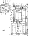
- FIG. 2 shows one end of the roller 1 with bearing, guide and actuator.
- the bearing 10 consists of a pin 11 which is axially displaceably mounted in the inner tube 27 of the roller 1 and can be pressed into the inner tube 27 against the force of a spring 13.
- This pin 11 lies in a pin receptacle 12 which is inserted into the sleeve 20.
- the Pin 11 can be pushed against the spring 13 so far into the inner tube 27 of the roller 1 that the pin at the other end of the roller 1 moves out of the pin receptacle and the roller 1 can thereby be pivoted away from the printing unit.
- the pin 11 is provided with a spherical surface, and the pin receptacle 12 has a dome-shaped design that matches it.
- the pin 11 is held in the tube 27 by a stop.
- the pin receptacle 12 is followed by a support 16 which has a rotatable ball 18 at its end, which can run on a surface of the machine frame 4.
- This support 16 provides for the absorption of the axial forces, a further support 15 of the same design being provided at the other end of the roller 1.
- the sleeve 20 contains a spring 24 which presses the pin receptacle 12 against a wall 32 of the sleeve 20 facing the plate cylinder 14.
- the pin receptacle 12 is radially displaceable in the sleeve 20 as seen from the plate cylinder 14, the receiving opening for the pin 11 remaining free through a recess 33.
- An exact displaceability of the pin receptacle 12 in the sleeve 20 is achieved by a piston-like sliding element 40 which carries the pin receptacle 12 and slides in the sleeve 20.
- the spring force of the spring 24 is dimensioned such that it holds the pin receptacle 12 on the wall 32 when the roller 1 is used as intended, but that it is compressed in the event that a hand gets between the plate cylinder 14 and the roller 1 and thereby the risk of injury is kept as low as possible.
- the sleeve 19 at the other end of the roller 1 is designed accordingly.
- FIG. 2 further shows the structure of the roller 1.
- This consists of an inner tube 27 and an outer tube 28, the inner tube 27 receiving the roll-side parts of the bearings.
- This is the pin 11.
- Rolling bearings 29 are arranged between the outer tube 28 and the inner tube 27, which ensure that the outer tube 28 can be easily rotated.
- On the surface of the outer tube 28 of the roller 1 there are grooves into which rings 30 made of elastic material are inserted in such a way that they protrude beyond the roller surface.
- rings 30 made of elastic material
- the actuating element 8 is screwed onto an angle 34, which is firmly connected to the machine frame 4.
- the roller 1 is mounted on the opposite side, not shown, in the same way, but it is sufficient if the pin is axially displaceable against the force of a spring on only one side. In this case, it is also not absolutely necessary for the non-displaceable pin or the associated pin receptacle to be spherical or dome-shaped. To avoid damage, however, this is useful.
- Figure 3 shows the device shortly before inserting the rear edge 3 of the pressure plate 2.
- the illustration shows a section between the adjusting element 8 and the angle 34, the guide elements 22, 22 ', 22'',22'' and the bearing lever 25 are cut.
- the direction of view is of the roller 1, the parts of its storage being visible at the right end.
- the paired arrangement of the guide elements is clearly visible.
- All guide elements are screwed into the side wall 4.
- they In order to show the appropriate structure of the guide elements, they are shown in section. They each consist of a screwed-in screw 35 and a sleeve 36 placed over it, which is easily rotatable.
- Holding disks 37 on each guide element ensure that the sleeve 20 is also guided in the direction of the axis of the roller 1.
- the holding washers 37 are held by the screw heads 38 (FIG. 1).
- the pressure plate 2 is shown in a position in which it is placed around the plate cylinder 14 and its rear edge 3 still has to be inserted into the clamping device 31.
- the sleeve 20 is displaced in the direction of the plate cylinder 14.
- the sleeve 19 is moved at the other end of the roller 1.
- the rear edge 3 of the pressure plate 2 comes into the position 39 shown in broken lines, in which it is located in the tensioning device 31.
- the clamping device 31 is then closed, the rear edge of the printing plate is clamped in, and the printing plate is clamped around the plate cylinder 14 by means of the clamping device 31.
- Figure 3 shows the spring 24 in the sleeve 20 which holds the bearing 10 of the roller 1 in the position facing the plate cylinder 14.
- this design serves to protect a hand between the plate cylinder 14 and roller 1 from injury by the roller 1 being able to deflect against the spring 24.
- the pivoted lever 25 mounted in the machine frame 4 is connected at one end to the bearing of the roller 1 and is designed such that when the roller 1 deflects in this way, a switch 26 is actuated at the other end of the lever 25 and the signal of the switch 26 stopping the press causes.
- the lever 25 has not been drawn in in FIGS. 1 and 2.
- the roller 1 can already be actuated by the actuating elements after inserting the leading edge of the printing plate, in order to ensure that the printing plate 2 is properly applied to the plate cylinder 14. If this function is provided, the roller 1 must be moved away from the plate cylinder 14 shortly before reaching the rear edge 3 of the pressure plate 2, in order thereby to be able to push the angled rear edge 3 of the pressure plate 2 into the tensioning device 31 and thus to position 39 promote.
- Figure 4 shows the combination of the device for inserting the angled rear edge of the printing plate with a device for semi-automatic printing plate feed.
- a printing unit 50 is shown, in which a plate cylinder 14 is located.
- This plate cylinder 14 is equipped with a device for clamping the printing plate leading edge 41 and with a clamping device 31 for clamping the printing plate trailing edge.
- the semi-automatic printing plate feeder consists of at least one roller 43 which is arranged such that its side facing the pressure device in the plate changing position lies essentially on a straight line which runs parallel to the clamping surfaces 42 of the device 41 for clamping the printing plate leading edge between these clamping surfaces 42 and leads out at an angle from the printing unit 50.
- the roller 1 is arranged such that it is located at the lower end of this straight line with little lateral displacement.
- the printing plate 2 is fed in such a way that the printer guides the printing plate 2 with its front edge past the side of the roller 43 facing the printing unit and inserts it into the clamping surfaces 42 for receiving the printing plate front edge.
- registration bolts are used in the Device 41 for clamping the pressure plate leading edge, which cooperate with U-shaped recesses in the pressure plate.
- the printer triggers the closing of the device 41, which is followed by a rotation of the plate cylinder 14, by means of which the printing plate 2 is wound onto the plate cylinder.
- roller 43 After the pressure plate trailing edge passes the roller 43, it falls down due to its weight, whereby it is caught by the roller 1.
- the roller 1 guides the printing plate and then serves in the manner described to insert the trailing edge of the printing plate. If the pressure plate trailing edge is inserted into the clamping device 31, it closes by clamping the pressure plate in order to subsequently clamp the pressure plate by a movement in the circumferential direction.
- the at least one roller 43 which is expediently designed as an easily rotatable roller, which has the width of the printing plate, is arranged on a lower part of a two-part printing unit guard 46. It is so far away from the printing unit protection that the angled rear edge 3 of the printing plate 2 can run past the printing unit protection 46.
- the lower part of the two-part printing unit guard 46 when folded up, assumes a position in which it is parallel to the straight line mentioned above. In this way, the roller 43 can be moved into its plate changing position when the printing unit guard 46 is folded up.
- a suction cup 44 is arranged at the upper end of this lower part of the two-part printing unit guard 46, against which the printing plate 2 can be pressed.
- the suction cup 44 is designed so that the pressure plate can slide on it.
- the presence of this bore 45 is used for venting the suction cup 44. In this way it is achieved that the suction cup 44 releases the pressure plate in time, the weight sags it a little way down and the rear edge 3 of the pressure plate can slide under this suction cup 44.
- FIG. 4 further shows how the two-part printing unit guard 46 has a hinge 49, is pivotally attached to the printing unit 50 by an angular arm and is guided on the printing unit 50 by means of a guide 48 at the lower end.
- a gas pressure spring 47 or a pneumatic element arranged at this point serve to hold the printing unit protection in its folded-up position or to convey it into this position.
- Fig. 5 shows the combination of the device for inserting the angled rear edge of the printing plate with a device for fully automatic printing plate supply and removal.
- This device consists of a magazine 51 for receiving used printing plates which have been removed from the machine and for new printing plates which can be fed to the machine.
- This magazine is expediently constructed in such a way that a cassette 52 for accommodating a number of new printing plates is accommodated in one room of the magazine 51 and a cassette 53 for accommodating a number of old printing plates is located in another room of the magazine 51.
- a transport device 55 is arranged for new printing plates, which has a plurality of suction cups 54, which serve to grip a new printing plate.
- the supply of new printing plates takes place in such a way that the printer first inserts a cassette 52 with several new printing plates into the magazine 51 and then the suction cups 54 are lowered, grasp a printing plate, lift it first and then by means of the transport device 55 into the device 41 insert to clamp the front edge of the printing plate.
- the suction cups 54 can be moved on a straight line which leads between the clamping surfaces 42 which are in a clamping position with a gap for receiving the plates in order to accommodate the leading edge of the printing plate.
- the printing plate After the printing plate has been inserted, it is clamped by means 41 for clamping the leading edge of the printing plate and wound around the plate cylinder 14.
- the pressure plate trailing edge is inserted by the roller 1 into the clamping device 31 in the manner already described.
- the tensioning device 31 and the device 41 are only shown symbolically. To remove the printing plates, they are released by the clamping device 31 and pushed into the lower part of the magazine 51. There they are gripped by one or more suction cups 56 and transported by means of the transport device 57 until they can be stored in the cassette 53 for the reception of old printing plates.
- Figures 4 and 5 show how the device for plate change, as described in claim 1 and further developed in the following claims, can be combined with a device for semi-automatic printing plate supply and with a device for fully automatic printing plate supply and removal, without that made changes to this device in terms of its structure Need to become. In this way it is possible to combine this device as a standardized element with both the semi-automatic and the fully automatic.
Landscapes
- Supply, Installation And Extraction Of Printed Sheets Or Plates (AREA)
- Massaging Devices (AREA)
- Iron Core Of Rotating Electric Machines (AREA)
- Addition Polymer Or Copolymer, Post-Treatments, Or Chemical Modifications (AREA)
- Registering, Tensioning, Guiding Webs, And Rollers Therefor (AREA)
- Magnetic Heads (AREA)
- Manufacturing Of Printed Circuit Boards (AREA)
Applications Claiming Priority (4)
| Application Number | Priority Date | Filing Date | Title |
|---|---|---|---|
| DE4128538 | 1991-08-28 | ||
| DE4128538 | 1991-08-28 | ||
| DE4218602A DE4218602C2 (de) | 1991-08-28 | 1992-06-05 | Vorrichtung zum Einführen der Druckplattenhinterkante an einem Plattenzylinder |
| DE4218602 | 1992-06-05 |
Publications (2)
| Publication Number | Publication Date |
|---|---|
| EP0531748A1 true EP0531748A1 (fr) | 1993-03-17 |
| EP0531748B1 EP0531748B1 (fr) | 1995-06-14 |
Family
ID=25906778
Family Applications (1)
| Application Number | Title | Priority Date | Filing Date |
|---|---|---|---|
| EP92113998A Expired - Lifetime EP0531748B1 (fr) | 1991-08-28 | 1992-08-17 | Dispositif pour remplacer des plaques d'impression |
Country Status (9)
| Country | Link |
|---|---|
| US (1) | US5309832A (fr) |
| EP (1) | EP0531748B1 (fr) |
| JP (1) | JP3273638B2 (fr) |
| CN (1) | CN1070609A (fr) |
| AT (1) | ATE123702T1 (fr) |
| AU (1) | AU655652B2 (fr) |
| CA (1) | CA2076790C (fr) |
| DE (2) | DE4218602C2 (fr) |
| HK (1) | HK19096A (fr) |
Cited By (8)
| Publication number | Priority date | Publication date | Assignee | Title |
|---|---|---|---|---|
| EP0567754A1 (fr) * | 1992-04-29 | 1993-11-03 | Heidelberger Druckmaschinen Aktiengesellschaft | Dispositif pour amener une plaque d'impression à un cylindre de plaque d'une machine à imprimer |
| EP0639454A1 (fr) * | 1993-08-20 | 1995-02-22 | Heidelberger Druckmaschinen Aktiengesellschaft | Dispositif à crochet escamotable pour maintenir une plaque d'impression sur un cylindre porte-plaque dans une imprimante rotative et imprimante rotative comportant un tel dispositif |
| EP0655330A1 (fr) * | 1993-11-26 | 1995-05-31 | Sakurai Graphic Systems Corp. | Dispositif de chargement de cliché dans une machine à imprimer |
| EP0687562A3 (fr) * | 1994-06-16 | 1996-11-13 | Roland Man Druckmasch | Méthode et appareil pour le montage de plaques d'impression flexibles |
| EP0739728A3 (fr) * | 1995-04-26 | 1997-04-16 | Heidelberger Druckmasch Ag | Procédé et dispositif pour fixer un cliché sur un cylindre |
| US5678487A (en) * | 1995-11-15 | 1997-10-21 | Heidelberg Harris Inc. | Apparatus for mounting flexible plates in a printing unit |
| WO2004020199A3 (fr) * | 2002-08-21 | 2004-05-06 | Koenig & Bauer Ag | Dispositif pour guider un habillage sur le cylindre d'une machine d'impression |
| WO2004085158A3 (fr) * | 2003-03-28 | 2005-06-02 | Koenig & Bauer Ag | Dispositif et procede de stockage d'au moins deux blanchets evacues successivement du meme cylindre d'une presse |
Families Citing this family (29)
| Publication number | Priority date | Publication date | Assignee | Title |
|---|---|---|---|---|
| DE4129022A1 (de) | 1991-08-31 | 1993-03-11 | Heidelberger Druckmasch Ag | Magazin fuer den automatischen druckplattenwechsel |
| DE4130359C2 (de) * | 1991-09-12 | 1997-04-17 | Heidelberger Druckmasch Ag | Vorrichtung zum Ab- und/oder Zuführen von Druckplatten einer Druckmaschine |
| FR2709168B1 (fr) * | 1993-08-20 | 1995-11-10 | Heidelberg Harris Sa | Dispositif de liaison fluidique temporaire entre une source de fluide sous pression et un organe utilisateur. |
| FR2709091B1 (fr) * | 1993-08-20 | 1995-11-10 | Heidelberg Harris Sa | Dispositif à lame interchangeable pour maintenir une plaque d'impression sur un cylindre porte-plaque dans une imprimante rotative, et outil de démontage de la lame. |
| DE4339344C1 (de) * | 1993-11-18 | 1995-03-30 | Roland Man Druckmasch | Vorrichtung für das automatisierte Wechseln von Druckplatten einer Druckmaschine |
| DE4407791C2 (de) * | 1994-03-09 | 1997-07-10 | Kba Planeta Ag | Biegsame Druckplatte |
| DE4414443C1 (de) * | 1994-04-26 | 1995-11-30 | Heidelberger Druckmasch Ag | Vorrichtung zum Führen eines Druckträgers |
| DE4416296C2 (de) * | 1994-05-09 | 1997-09-04 | Roland Man Druckmasch | Vorrichtung zum Aufziehen flexibler Druckformen |
| DE4417054B4 (de) * | 1994-05-14 | 2007-01-11 | Heidelberger Druckmaschinen Ag | Andrückvorrichtung im Druckwerk einer Druckmaschine |
| DE4438754C2 (de) * | 1994-10-29 | 1998-02-19 | Roland Man Druckmasch | Aufhängung für ein an einem Zylinder einer Druckmaschine an- und abstellbares Andrückelement |
| DE4440239C5 (de) * | 1994-11-10 | 2007-11-22 | Man Roland Druckmaschinen Ag | Wälzelement zum Andrücken einer flexiblen Druckplatte an den Formzylinder |
| DE4447124C1 (de) * | 1994-12-29 | 1996-02-08 | Koenig & Bauer Albert Ag | Zylinder einer Rotationsdruckmaschine |
| FR2735418B1 (fr) * | 1995-06-19 | 1997-08-22 | Heidelberg Harris Sa | Dispositif d'echange de plaques de groupes d'impression de machines a imprimer |
| US6113346A (en) | 1996-07-31 | 2000-09-05 | Agfa Corporation | Method for loading and unloading a supply of plates in an automated plate handler |
| DE19639800C1 (de) * | 1996-09-27 | 1998-02-05 | Kba Planeta Ag | Vorrichtung zum Positionieren des freien Endes einer Druckplatte |
| US5816154A (en) * | 1997-05-09 | 1998-10-06 | Bryce International, L.L.C. | Print cylinder support for axial removal of a cylindrical sleeve |
| DE19816659B4 (de) * | 1997-05-26 | 2005-04-07 | Heidelberger Druckmaschinen Ag | Verfahren und Vorrichtung zum Schutz gegen das Eindringen von Fremdkörpern in einen Walzenspalt |
| DE10000904A1 (de) * | 1999-02-10 | 2000-08-17 | Heidelberger Druckmasch Ag | Verfahren und Vorrichtung zur Bereitstellung und Zuführung von Druckformen |
| DE10010056B4 (de) * | 1999-03-31 | 2012-11-08 | Heidelberger Druckmaschinen Ag | Druckplattenwechsler |
| JP2003103759A (ja) * | 2001-10-01 | 2003-04-09 | Lintec Corp | 印刷装置におけるロール支持構造 |
| ATE314201T1 (de) * | 2001-11-28 | 2006-01-15 | Koenig & Bauer Ag | Verfahren zum montieren eines aufzugs auf einer mantelfläche eines zylinders einer druckmaschine |
| DE102004022866A1 (de) * | 2003-07-11 | 2005-01-27 | Koenig & Bauer Ag | Vorrichtung und Verfahren zum Aufziehen und/oder Abnehmen einer Druckform |
| DE102006048676B4 (de) * | 2006-10-14 | 2011-07-07 | KOENIG & BAUER Aktiengesellschaft, 97080 | Einrichtung zum Erkennen eines Vorhandenseins eines Aufzugs auf einem Zylinder |
| CN102886974A (zh) * | 2011-07-22 | 2013-01-23 | 盐城市远华机械有限公司 | 空心花辊传动夹紧机构 |
| DE102016206223A1 (de) * | 2015-05-22 | 2016-11-24 | Heidelberger Druckmaschinen Ag | Plattenwechsler |
| CN105711253A (zh) * | 2016-02-29 | 2016-06-29 | 马宁 | 一种印刷滚筒表面缺陷检测用套柱 |
| JP6832079B2 (ja) * | 2016-06-13 | 2021-02-24 | 三菱重工機械システム株式会社 | 版締めシステム及び印刷機 |
| WO2018197164A1 (fr) * | 2017-04-26 | 2018-11-01 | Kba-Metalprint Gmbh | Unité d'impression prévue pour imprimer des supports d'impression en feuille, machine pour impression sur métaux avec une telle unité d'impression et procédé de montage d'ascenseurs dans les cylindres d'une unité d'impression pour imprimante sur feuilles |
| CN113199858B (zh) * | 2021-04-12 | 2022-07-12 | 广州钜龙包装设备有限公司 | 一种柔性版拆版机 |
Family Cites Families (5)
| Publication number | Priority date | Publication date | Assignee | Title |
|---|---|---|---|---|
| JPS62169646A (ja) * | 1986-01-22 | 1987-07-25 | Mitsubishi Heavy Ind Ltd | 印刷機の版胴における版の尻側端部插入装置 |
| JPS62169647A (ja) * | 1986-01-22 | 1987-07-25 | Mitsubishi Heavy Ind Ltd | 印刷機の版胴における版の尻側端部取外し装置 |
| JP2726661B2 (ja) * | 1986-09-18 | 1998-03-11 | 三菱重工業株式会社 | 枚葉印刷機の版尻挿入装置 |
| DE3940796A1 (de) * | 1989-12-09 | 1991-06-13 | Koenig & Bauer Ag | Verfahren und einrichtung zum automatischen wechseln einer druckplatte |
| DE3940795A1 (de) * | 1989-12-09 | 1991-06-13 | Koenig & Bauer Ag | Verfahren und einrichtung zum automatischen zufuehren bzw. abfuehren einer druckplatte |
-
1992
- 1992-06-05 DE DE4218602A patent/DE4218602C2/de not_active Expired - Fee Related
- 1992-08-17 DE DE59202515T patent/DE59202515D1/de not_active Expired - Lifetime
- 1992-08-17 EP EP92113998A patent/EP0531748B1/fr not_active Expired - Lifetime
- 1992-08-17 AT AT92113998T patent/ATE123702T1/de not_active IP Right Cessation
- 1992-08-25 CA CA002076790A patent/CA2076790C/fr not_active Expired - Fee Related
- 1992-08-27 AU AU21306/92A patent/AU655652B2/en not_active Ceased
- 1992-08-27 CN CN92109728A patent/CN1070609A/zh active Pending
- 1992-08-28 JP JP23033292A patent/JP3273638B2/ja not_active Expired - Fee Related
- 1992-08-28 US US07/937,528 patent/US5309832A/en not_active Expired - Lifetime
-
1996
- 1996-02-01 HK HK19096A patent/HK19096A/xx not_active IP Right Cessation
Non-Patent Citations (2)
| Title |
|---|
| PATENT ABSTRACTS OF JAPAN vol. 11, no. 196 (M-601)(2643) 24. Juni 1987 & JP-A-62 019 458 ( AKIYAMA INSATSUKI SEIZO K.K. ) * |
| PATENT ABSTRACTS OF JAPAN vol. 12, no. 466 (M-772)(3313) 7. Dezember 1988 & JP-A-63 191 636 ( MITSUBISHI HEAVY IND LTD ) * |
Cited By (14)
| Publication number | Priority date | Publication date | Assignee | Title |
|---|---|---|---|---|
| EP0567754A1 (fr) * | 1992-04-29 | 1993-11-03 | Heidelberger Druckmaschinen Aktiengesellschaft | Dispositif pour amener une plaque d'impression à un cylindre de plaque d'une machine à imprimer |
| EP0639454A1 (fr) * | 1993-08-20 | 1995-02-22 | Heidelberger Druckmaschinen Aktiengesellschaft | Dispositif à crochet escamotable pour maintenir une plaque d'impression sur un cylindre porte-plaque dans une imprimante rotative et imprimante rotative comportant un tel dispositif |
| FR2709090A1 (fr) * | 1993-08-20 | 1995-02-24 | Heidelberg Harris Sa | Dispositif à crochet et escamotable pour maintenir une plaque d'impression sur un cylindre porte-plaque, dans une imprimante rotative, et imprimante rotative comportant un tel dispositif. |
| EP0655330A1 (fr) * | 1993-11-26 | 1995-05-31 | Sakurai Graphic Systems Corp. | Dispositif de chargement de cliché dans une machine à imprimer |
| EP0687562A3 (fr) * | 1994-06-16 | 1996-11-13 | Roland Man Druckmasch | Méthode et appareil pour le montage de plaques d'impression flexibles |
| US5718175A (en) * | 1995-04-26 | 1998-02-17 | Heidelberger Harris Inc. | Method and apparatus for mounting a printing plate on a cylinder |
| EP0739728A3 (fr) * | 1995-04-26 | 1997-04-16 | Heidelberger Druckmasch Ag | Procédé et dispositif pour fixer un cliché sur un cylindre |
| US5678487A (en) * | 1995-11-15 | 1997-10-21 | Heidelberg Harris Inc. | Apparatus for mounting flexible plates in a printing unit |
| WO2004020199A3 (fr) * | 2002-08-21 | 2004-05-06 | Koenig & Bauer Ag | Dispositif pour guider un habillage sur le cylindre d'une machine d'impression |
| US7237483B2 (en) | 2002-08-21 | 2007-07-03 | Koenig & Bauer Aktiengesellschaft | Device for guiding a dressing on a cylinder of a printing press |
| WO2004085158A3 (fr) * | 2003-03-28 | 2005-06-02 | Koenig & Bauer Ag | Dispositif et procede de stockage d'au moins deux blanchets evacues successivement du meme cylindre d'une presse |
| US7530309B2 (en) | 2003-03-28 | 2009-05-12 | Koenig & Bauer Aktiengesellschaft | Device for storing at least two dressings that are drawn off from the same cylinder of a printing machine one after another |
| CN100588540C (zh) * | 2003-03-28 | 2010-02-10 | 柯尼格及包尔公开股份有限公司 | 对从印刷机同一滚筒先后输出的至少两个包衬进行储存的装置和方法 |
| US7806052B2 (en) | 2003-03-28 | 2010-10-05 | Koenig & Bauer Aktiengesellschaft | Printing forme magazine with a receiving arrangement for receiving a plurality of printing formes to be mounted on a forme cylinder of a printing press |
Also Published As
| Publication number | Publication date |
|---|---|
| AU2130692A (en) | 1993-03-04 |
| JPH05220933A (ja) | 1993-08-31 |
| DE4218602A1 (de) | 1993-03-04 |
| ATE123702T1 (de) | 1995-06-15 |
| CN1070609A (zh) | 1993-04-07 |
| US5309832A (en) | 1994-05-10 |
| DE59202515D1 (de) | 1995-07-20 |
| CA2076790A1 (fr) | 1993-03-01 |
| JP3273638B2 (ja) | 2002-04-08 |
| EP0531748B1 (fr) | 1995-06-14 |
| AU655652B2 (en) | 1995-01-05 |
| HK19096A (en) | 1996-02-09 |
| DE4218602C2 (de) | 1993-11-11 |
| CA2076790C (fr) | 1998-05-05 |
Similar Documents
| Publication | Publication Date | Title |
|---|---|---|
| EP0531748B1 (fr) | Dispositif pour remplacer des plaques d'impression | |
| EP0933206B1 (fr) | Procédé et dispositifs pour amener et/ou enlever automatiquement des plaques d'impression vers le/du cylindre porte-plaque d'une machine à imprimer | |
| DE3818001C3 (de) | Stanzmaschine mit ein- und auswechselbarem Stanzwerkzeug und mit einem Werkstückvorschub | |
| DE3744961C2 (de) | Rollenschneidemaschine | |
| DE4339344C1 (de) | Vorrichtung für das automatisierte Wechseln von Druckplatten einer Druckmaschine | |
| DE69508976T2 (de) | Vorrichtung zum Zuführen von Rollen zu einer Verwendungsmaschine | |
| EP0567754A1 (fr) | Dispositif pour amener une plaque d'impression à un cylindre de plaque d'une machine à imprimer | |
| DE69300341T2 (de) | Apparat zur Handhabung von Rollen aus bahnförmigem Material. | |
| DE69908224T2 (de) | Vorrichtung zur automatischen Befestigung einer eine Spule tragenden Welle an einem Maschinendorn | |
| EP0660779B1 (fr) | Dispositif permettant d'amener des plaques d'impression jusqu'a un cylindre de plaques et a les en eloigner | |
| EP0358030B1 (fr) | Dispositif pour séparer individuellement les tubes coniques empilés les uns sur les autres | |
| DE102013108831A1 (de) | Rollenhandlingsystem mit einer einseitig lösbar befestigten Wickelwelle | |
| DE1574426B1 (de) | Wickelmaschine zum Aufwickeln von kontinuierlich erzeugten Warenbahnen | |
| DE2461622B2 (de) | Vorrichtung zur Übergabe von Spinnhülsen | |
| DE69303916T2 (de) | Vorrichtung zum Wechseln von Druckplatten in einer Druckmaschine | |
| DE102013108829B4 (de) | Rollenhandlingsystem für einen Wickler sowie Verfahren hierzu | |
| DE19724635C2 (de) | Werkzeugmaschine mit Werkzeugauswechselvorrichtung | |
| DE2754176A1 (de) | Vorrichtung zum beladen von werkzeugmaschinen, insbesondere drehmaschinen | |
| DE2528222C2 (de) | Magazin für Spulenhülsen | |
| EP0887297B1 (fr) | Dispositif d'enroulage pour une bande de matière, en particulier pour un dispositif de coupe à rouleaux | |
| DE19856517A1 (de) | Verfahren und Vorrichtung zum Walzenaustausch bei einem Kalander | |
| DE69608149T2 (de) | Bilderzeugungsgerät mit einer Aufnahme für eine Rolle Bildempfangsmaterials | |
| DE19829875B4 (de) | Vorrichtung zum Aufbringen einer Platte auf einen Plattenzylinder einer Druckmaschine | |
| DE3524648A1 (de) | Anordnung zum aufwickeln von flachmaterial | |
| DE4119290A1 (de) | Vorrichtung zum spulenwechsel in einer bandmaterial verarbeitenden maschine |
Legal Events
| Date | Code | Title | Description |
|---|---|---|---|
| PUAI | Public reference made under article 153(3) epc to a published international application that has entered the european phase |
Free format text: ORIGINAL CODE: 0009012 |
|
| 17P | Request for examination filed |
Effective date: 19920817 |
|
| AK | Designated contracting states |
Kind code of ref document: A1 Designated state(s): AT CH DE FR GB IT LI NL SE |
|
| GBC | Gb: translation of claims filed (gb section 78(7)/1977) | ||
| 17Q | First examination report despatched |
Effective date: 19941111 |
|
| GRAA | (expected) grant |
Free format text: ORIGINAL CODE: 0009210 |
|
| AK | Designated contracting states |
Kind code of ref document: B1 Designated state(s): AT CH DE FR GB IT LI NL SE |
|
| REF | Corresponds to: |
Ref document number: 123702 Country of ref document: AT Date of ref document: 19950615 Kind code of ref document: T |
|
| REF | Corresponds to: |
Ref document number: 59202515 Country of ref document: DE Date of ref document: 19950720 |
|
| ET | Fr: translation filed | ||
| ITF | It: translation for a ep patent filed | ||
| GBT | Gb: translation of ep patent filed (gb section 77(6)(a)/1977) |
Effective date: 19950814 |
|
| PLBE | No opposition filed within time limit |
Free format text: ORIGINAL CODE: 0009261 |
|
| 26N | No opposition filed | ||
| PGFP | Annual fee paid to national office [announced via postgrant information from national office to epo] |
Ref country code: AT Payment date: 19970723 Year of fee payment: 6 |
|
| PGFP | Annual fee paid to national office [announced via postgrant information from national office to epo] |
Ref country code: SE Payment date: 19970822 Year of fee payment: 6 |
|
| PG25 | Lapsed in a contracting state [announced via postgrant information from national office to epo] |
Ref country code: AT Free format text: LAPSE BECAUSE OF NON-PAYMENT OF DUE FEES Effective date: 19980817 |
|
| PG25 | Lapsed in a contracting state [announced via postgrant information from national office to epo] |
Ref country code: SE Free format text: LAPSE BECAUSE OF NON-PAYMENT OF DUE FEES Effective date: 19980818 |
|
| PGFP | Annual fee paid to national office [announced via postgrant information from national office to epo] |
Ref country code: NL Payment date: 19980825 Year of fee payment: 7 |
|
| EUG | Se: european patent has lapsed |
Ref document number: 92113998.6 |
|
| PG25 | Lapsed in a contracting state [announced via postgrant information from national office to epo] |
Ref country code: NL Free format text: LAPSE BECAUSE OF NON-PAYMENT OF DUE FEES Effective date: 20000301 |
|
| NLV4 | Nl: lapsed or anulled due to non-payment of the annual fee |
Effective date: 20000301 |
|
| REG | Reference to a national code |
Ref country code: GB Ref legal event code: IF02 |
|
| PGFP | Annual fee paid to national office [announced via postgrant information from national office to epo] |
Ref country code: GB Payment date: 20020722 Year of fee payment: 11 |
|
| PGFP | Annual fee paid to national office [announced via postgrant information from national office to epo] |
Ref country code: FR Payment date: 20020820 Year of fee payment: 11 |
|
| PGFP | Annual fee paid to national office [announced via postgrant information from national office to epo] |
Ref country code: CH Payment date: 20020903 Year of fee payment: 11 |
|
| PG25 | Lapsed in a contracting state [announced via postgrant information from national office to epo] |
Ref country code: GB Free format text: LAPSE BECAUSE OF NON-PAYMENT OF DUE FEES Effective date: 20030817 |
|
| PG25 | Lapsed in a contracting state [announced via postgrant information from national office to epo] |
Ref country code: LI Free format text: LAPSE BECAUSE OF NON-PAYMENT OF DUE FEES Effective date: 20030831 Ref country code: CH Free format text: LAPSE BECAUSE OF NON-PAYMENT OF DUE FEES Effective date: 20030831 |
|
| GBPC | Gb: european patent ceased through non-payment of renewal fee |
Effective date: 20030817 |
|
| REG | Reference to a national code |
Ref country code: CH Ref legal event code: PL |
|
| PG25 | Lapsed in a contracting state [announced via postgrant information from national office to epo] |
Ref country code: FR Free format text: LAPSE BECAUSE OF NON-PAYMENT OF DUE FEES Effective date: 20040430 |
|
| REG | Reference to a national code |
Ref country code: FR Ref legal event code: ST |
|
| PG25 | Lapsed in a contracting state [announced via postgrant information from national office to epo] |
Ref country code: IT Free format text: LAPSE BECAUSE OF NON-PAYMENT OF DUE FEES Effective date: 20050817 |
|
| PGFP | Annual fee paid to national office [announced via postgrant information from national office to epo] |
Ref country code: DE Payment date: 20100920 Year of fee payment: 19 |
|
| REG | Reference to a national code |
Ref country code: DE Ref legal event code: R119 Ref document number: 59202515 Country of ref document: DE Effective date: 20120301 |
|
| PG25 | Lapsed in a contracting state [announced via postgrant information from national office to epo] |
Ref country code: DE Free format text: LAPSE BECAUSE OF NON-PAYMENT OF DUE FEES Effective date: 20120301 |