EP0532032B1 - Dispositif d'ajustement rapide pour un système de retenue par bande - Google Patents
Dispositif d'ajustement rapide pour un système de retenue par bande Download PDFInfo
- Publication number
- EP0532032B1 EP0532032B1 EP92115583A EP92115583A EP0532032B1 EP 0532032 B1 EP0532032 B1 EP 0532032B1 EP 92115583 A EP92115583 A EP 92115583A EP 92115583 A EP92115583 A EP 92115583A EP 0532032 B1 EP0532032 B1 EP 0532032B1
- Authority
- EP
- European Patent Office
- Prior art keywords
- housing
- base plate
- button
- opening
- push
- Prior art date
- Legal status (The legal status is an assumption and is not a legal conclusion. Google has not performed a legal analysis and makes no representation as to the accuracy of the status listed.)
- Expired - Lifetime
Links
Images

Classifications
-
- B—PERFORMING OPERATIONS; TRANSPORTING
- B60—VEHICLES IN GENERAL
- B60R—VEHICLES, VEHICLE FITTINGS, OR VEHICLE PARTS, NOT OTHERWISE PROVIDED FOR
- B60R22/00—Safety belts or body harnesses in vehicles
- B60R22/30—Coupling devices other than buckles, including length-adjusting fittings or anti-slip devices
-
- A—HUMAN NECESSITIES
- A44—HABERDASHERY; JEWELLERY
- A44B—BUTTONS, PINS, BUCKLES, SLIDE FASTENERS, OR THE LIKE
- A44B11/00—Buckles; Similar fasteners for interconnecting straps or the like, e.g. for safety belts
- A44B11/25—Buckles; Similar fasteners for interconnecting straps or the like, e.g. for safety belts with two or more separable parts
- A44B11/2503—Safety buckles
- A44B11/2546—Details
- A44B11/2553—Attachment of buckle to strap
- A44B11/2557—Attachment of buckle to strap with strap length adjustment
Definitions
- the invention relates to a quick adjuster for a webbing restraint system, comprising a housing made of resilient material, a base plate fastened to the housing by means of a snap connection with a passage for a rear webbing and a mechanism for clamping a front webbing that can be released by means of a spring-loaded push button.
- Such a quick adjuster with the features of the preamble of claim 1 is disclosed in DE-U-90 01 502.
- the relatively thin-walled housing of this quick adjuster is connected to the base plate by means of a plurality of essentially lateral snap connections and a front rivet attachment.
- the spring-loaded pushbutton is designed as a rotary element and is mounted on the side of the housing in the rotary manner. This button is actuated from the side of the quick adjuster and moves back a sliding plate of the mechanism for clamping the front webbing, which is wrapped around a clamping web of this plate and passes through the base plate downwards.
- the housing easily detaches from the base plate and then protrudes therefrom so that it does occur can that the quick adjuster clings to the clothing of the person secured with the restraint system. There is also a certain risk of injury to people due to the exposed area of the base plate. Furthermore, the detached rear end of the housing affects the safe function of the quick adjuster when the front webbing is pulled tight. Furthermore, the pushbutton acts only close to the edge on its sliding plate when it is actuated in order to release the mechanism, thereby causing an asymmetrical loading of this plate, so that in some cases this plate can be difficult to open because it can tilt.
- the object of the invention is to improve a quick adjuster of the type mentioned, which ensures simple and permanently secure attachment of the housing to the base plate with a compact structure of the adjuster.
- the housing can still be made of thin-walled plastic, it being ensured at all times that it remains completely connected to the base plate, that is to say it cannot detach from it.
- Detachment of the rear snap connection of the housing from the base plate is prevented by the rear webbing, the thickness of which corresponds to the remaining gap in the passage between the rear of the snap connection and the opposite edge of the passage, so that the snap projection of the housing has no scope for rearward detachment has more.
- the front, pocket-like recess of the housing completely takes up the front edge area of the base plate, so that the base plate can neither move to the side nor downwards.
- the further advantage of such a housing attachment to the base plate further consists in that the otherwise usual lateral snap connections of the housing for the lateral fixing of the base plate can be omitted, which has a cost-reducing effect on the manufacturing costs of the quick adjuster.
- the adjuster housing being designed for the longitudinally displaceable reception of the push button, so that it is pressed from the front of the adjuster.
- the pushbutton in the front area of its underside can have a cut-out for the passage of the front webbing which is delimited by side runners, the side runners each being provided with a front bevel and the pushbutton having a rear, upper paragraph which has a locking edge of the Housing cooperates.
- the push button only needs to be operated with the thumb alone, so that there is no need to hold the quick adjuster between the thumb and forefinger when the clamping mechanism of the adjuster is to be opened. Due to the longitudinally displaceable and central arrangement of the push button, the clamping mechanism is no longer actuated outside the longitudinal center of the quick adjuster, so that the clamping member of the mechanism which fixes the front webbing can no longer tilt when it is pushed back and ensures unimpeded opening of the mechanism and thus of the quick adjuster at all times is. Furthermore, such an arrangement of the push button also enables a relatively large adjustment path of the clamping member mentioned, so that the passage of the front belt webbing can be carried out easily and quickly.
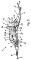
- the generally designated 1 quick adjuster comprises a housing 2 made of resilient material, for. B. made of flexible plastic, and a partially protruding from the housing push button 3 for actuating a clamping mechanism to be explained.
- a front webbing 4 with an end section 5 for tightening the webbing and a rear webbing 6.
- the webbing 4 and 6 are part of a webbing restraint system, such as. B. is used in motor vehicles to secure people.
- Preferred restraint systems, where the quick adjuster described here can be used are so-called braces systems.
- the housing 2 has a front bracket 7, which surrounds a larger opening 8 with the rest of the housing 2 in order to guide the front webbing 4, i. H.
- the quick adjuster has a rear passage 9 through which the rear webbing 6 passes in the form of a loop and is sewn at 10 in the usual manner.
- the housing is approximately box-shaped and has an upper opening 11 from which the push button 3 protrudes.
- the button 3 can preferably be actuated with the thumb in the longitudinal direction of the quick adjuster according to the arrow 12 and, with a corresponding thumb pressure, moves from a front clamping position into a rear release position, in which the webbing 4 can be loosened in the usual manner by pulling.
- the pushbutton arrives by the pressure of a spring 13 automatically in its forward position.
- the internal structure of the quick adjuster 1 can be seen exactly from the sectional view according to FIG. It can be seen that a flat base plate 14 engages with its front edge in a pocket-shaped recess 15 of the housing 2.
- the recess 15 is formed such that the ends of the recess are limited by the material of the housing, so that the base plate 14 is thereby fixed on all sides in the recess 15.
- the base plate 14 has a rear passage 16 through which the rear webbing 6 passes.
- the housing 2 has a downwardly projecting snap projection 17 on a rear wall, which extends through the rear passage 16 downwards and engages behind the base plate 14, as clearly shown in FIG. 3.
- the housing 2 is at least positively attached to the base plate 14 in its rear region.
- a snap force also acts against the base plate 14 in order to reinforce the fixing of the housing 2 in the region of the rear passage 16 on the base plate.
- the snap projection 17 of the housing 2 passes through the passage 16 of the base plate 14 according to FIG. 3, the effective width of the passage 16 is reduced, so that there is a gap 18 which corresponds approximately to the thickness of the rear webbing 6 intended for this passage.
- the snap projection 17 can not move back and not get out of the passage 16, so that a secure and permanent fixation of the housing 2 on the Base plate 14 is ensured in the rear area of the quick adjuster 1.
- only one snap projection 17 is provided, which engages with one side of the area of the base plate 14 delimiting the passage 16.
- a further snap projection can also be provided, which lies opposite the snap projection 17 on the other side of the passage 16 and which starts from the housing material designated by 19.
- the aforementioned gap 18 for the implementation of the rear webbing 6 is then formed between these two snap projections.
- This alternative design in the rear area of the housing 2 for securely fixing it to the base plate 14 is not shown in the drawing.
- a sliding plate 20 which forms the aforementioned clamping mechanism and which has a transverse web 21 around which the front webbing 4 is wrapped.
- the front edge 22 of the crossbar 21 forms, together with the front edge 23 of the base plate 14, a customary clamping area for fixing the front webbing 4 or its front end section 5.
- the pushbutton 3 has in the front region of its underside a recess 24 opposite the crosspiece 21 in order to allow the belt webbing 4, 5 to pass through.
- the recess 24 is laterally limited by runners 25 which slide on the sliding plate 20.
- the side runners are each provided with a front bevel 26, which allow the push button 3 to be tilted in its front position when the webbing 4 is pulled in order to clamp it.
- the pushbutton 3 is further provided with a rear, upper shoulder 27 which interacts with a locking edge 28 of the housing 2.
- the locking edge 28 is preferably formed by an edge section of the upper housing opening 11.
- the compression spring 13 is arranged inclined so that a pressure component acts on the button 3, which brings the locking shoulder 27 into engagement with the locking edge 28 when the webbing 4 is pulled.
- the clamping position of the sliding plate 20 is secured in a certain way in order to avoid micro-slippage.
- the push button 3 is pressed in accordance with the arrow 12, the latching connection 27, 28 can be released quickly and easily by a corresponding pressure on the upwardly projecting part 3a of the push button 3, so that the button 3 is reset, with its lower projection 29 against the rear part of the sliding plate 20 is pressed and pushes it back.
- the compression spring 13 can, as shown, be a wire spring which is essentially fastened in the push button 3. But it can also consist of an integral part of the push button 3 or the housing 2, which are made of plastic.
Landscapes
- Engineering & Computer Science (AREA)
- Mechanical Engineering (AREA)
- Automotive Seat Belt Assembly (AREA)
- Purses, Travelling Bags, Baskets, Or Suitcases (AREA)
- Buckles (AREA)
Claims (5)
- Dispositif d'ajustement rapide pour un système de retenue par sangle, comprenant un boîtier (2) en un matériau flexible, une plaque de base (14) fixée au boîtier (2) au moyen d'une liaison par encliquetage et comportant un passage (16) pour une sangle arrière (6), et un mécanisme libérable au moyen d'un bouton-poussoir (3) sollicité par ressort, pour le serrage d'une sangle avant (4), caractérisé en ce que le boîtier (2) présente un évidement avant (15), en forme de poche, pour la réception du bord avant de la plaque de base (14), en ce qu'au moins une saillie d'encliquetage (17) du boîtier (2) pénètre dans le passage (16) de la plaque de base (14) pour la sangle arrière (6) et vient en prise, au moins par complémentarité de formes, à un bord de la plaque de base (14), qui limite cette ouverture, et en ce que la largeur de la fente (18), qui subsiste dans le passage arrière (16), correspond sensiblement à l'épaisseur de la sangle arrière (6) destinée à ce passage.
- Dispositif d'ajustement rapide selon la revendication 1, caractérisé en ce que le boîtier (2) est constitué de manière à recevoir, déplaçable longitudinalement, le bouton-poussoir (3).
- Dispositif d'ajustement rapide selon la revendication 2, caractérisé en ce que le bouton-poussoir (3) présente, dans la région avant de son côté inférieur, un évidement (24) limité par des patins latéraux (25), pour le passage de la sangle avant (4, 5), en ce que les patins latéraux (25) sont chacun pourvus d'un chanfrein avant (26) et en ce que le bouton-poussoir (3) présente un décrochement arrière supérieur (27), qui coopère avec une arête d'encliquetage (28) du boîtier (2).
- Dispositif d'ajustement rapide selon la revendication 3, caractérisé en ce que l'arête d'encliquetage (28) est formée par le bord d'une ouverture supérieure (11) du boîtier.
- Dispositif d'ajustement rapide selon la revendication 2 ou 3, caractérisé en ce que la force de sollicitation par ressort (13) du bouton-poussoir (3) présente une composante, qui amène le décochement supérieur (27) du bouton-poussoir (3) non actionné, avec basculement de ce dernier, en prise avec l'arête d'encliquetage (28) du boîtier (2).
Applications Claiming Priority (2)
| Application Number | Priority Date | Filing Date | Title |
|---|---|---|---|
| DE9111299U DE9111299U1 (de) | 1991-09-11 | 1991-09-11 | Schnellversteller für ein Gurtband-Rückhaltesystem |
| DE9111299U | 1991-09-11 |
Publications (2)
| Publication Number | Publication Date |
|---|---|
| EP0532032A1 EP0532032A1 (fr) | 1993-03-17 |
| EP0532032B1 true EP0532032B1 (fr) | 1995-05-17 |
Family
ID=6871159
Family Applications (1)
| Application Number | Title | Priority Date | Filing Date |
|---|---|---|---|
| EP92115583A Expired - Lifetime EP0532032B1 (fr) | 1991-09-11 | 1992-09-11 | Dispositif d'ajustement rapide pour un système de retenue par bande |
Country Status (3)
| Country | Link |
|---|---|
| EP (1) | EP0532032B1 (fr) |
| DE (2) | DE9111299U1 (fr) |
| ES (1) | ES2075558T3 (fr) |
Families Citing this family (5)
| Publication number | Priority date | Publication date | Assignee | Title |
|---|---|---|---|---|
| US7862124B2 (en) * | 1998-08-18 | 2011-01-04 | Indiana Mills And Manufacturing, Inc. | Web adjuster and coupling |
| US6273505B1 (en) * | 1999-10-22 | 2001-08-14 | Graco Children's Products Inc. | Web adjuster for infant products |
| US7252342B2 (en) | 2004-04-13 | 2007-08-07 | Graco Children's Products Inc. | Child restraint assembly for child vehicle seat |
| TWI694016B (zh) * | 2019-03-14 | 2020-05-21 | 王亮雄 | 織帶長度調整裝置 |
| CN111717152B (zh) * | 2019-03-18 | 2021-08-31 | 王亮雄 | 织带长度调整装置 |
Family Cites Families (2)
| Publication number | Priority date | Publication date | Assignee | Title |
|---|---|---|---|---|
| JPS5216737A (en) * | 1975-07-30 | 1977-02-08 | Toyota Motor Corp | Tongue plate mechanism of safety seat belt |
| DE8527732U1 (de) * | 1985-09-28 | 1986-02-13 | van Riesen & Co, 2080 Pinneberg | Einrichtung zur Längenverstellung von Sicherheitsgurtbändern |
-
1991
- 1991-09-11 DE DE9111299U patent/DE9111299U1/de not_active Expired - Lifetime
-
1992
- 1992-09-11 DE DE59202221T patent/DE59202221D1/de not_active Expired - Fee Related
- 1992-09-11 EP EP92115583A patent/EP0532032B1/fr not_active Expired - Lifetime
- 1992-09-11 ES ES92115583T patent/ES2075558T3/es not_active Expired - Lifetime
Also Published As
| Publication number | Publication date |
|---|---|
| EP0532032A1 (fr) | 1993-03-17 |
| DE9111299U1 (de) | 1991-10-31 |
| DE59202221D1 (de) | 1995-06-22 |
| ES2075558T3 (es) | 1995-10-01 |
Similar Documents
| Publication | Publication Date | Title |
|---|---|---|
| DE19829899B4 (de) | Reibschlüssige Gurteinstellvorrichtung | |
| EP0083752B1 (fr) | Boucle pour ceintures de sécurité | |
| DE2815638C2 (de) | Reißverschlußschieber | |
| DE2017683A1 (de) | Einspannvorrichtung für einen Sicherheitsgurt | |
| DE3841832A1 (de) | Verschlusseinrichtung fuer den kinnriemen eines motorradschutzhelms | |
| DE69604326T2 (de) | Einstellbarer Verschluss für Schuhe | |
| DE2641231A1 (de) | Schnallenverschluss fuer skistiefel o.dgl. | |
| DE3314099A1 (de) | Gefaessstauer mit einer gurtschnalle und einem staugurt | |
| DE602005004635T2 (de) | Fahrzeugkindersitz | |
| EP0532032B1 (fr) | Dispositif d'ajustement rapide pour un système de retenue par bande | |
| DE69201575T2 (de) | Verbindungseinrichtung einer in Achsrichtung verstellbaren Lenksäule mit aufschlagfunktionierenden Mitteln. | |
| EP0137374B1 (fr) | Boucle pour système de ceintures de sécurité | |
| DE4013158C2 (de) | Abdeckrollo für Kraftfahrzeuge | |
| DE1610699C3 (de) | GürtelverschluB | |
| EP0252403B1 (fr) | Boucle pour système de ceinture de sécurité | |
| DE29502987U1 (de) | Ausklinkbares Schnappschloß | |
| DE3330734C2 (fr) | ||
| EP0466860A1 (fr) | Elements de fixation de ski, en particulier machoires avant. | |
| DE4125028C2 (de) | Gurtverschluß für eine Sicherheitsgurtanordnung | |
| DE3401529A1 (de) | Verstellvorrichtung fuer einen sicherheitsgurt-anlenkpunkt | |
| DE60300131T2 (de) | Schliess- und Spannvorrichtung für Sportschuh oder für Bindungssystem für Gleitsportartikel | |
| DE3205417C2 (de) | Dachfenster für Kraftfahrzeuge | |
| DE29819150U1 (de) | Einstellbare Schloßbefestigungsvorrichtung | |
| DE2522274B2 (de) | Betaetigungsorgan fuer eine druckknopf-abstimmeinrichtung | |
| DE3624112A1 (de) | Anschnuervorrichtung fuer koerperteile |
Legal Events
| Date | Code | Title | Description |
|---|---|---|---|
| PUAI | Public reference made under article 153(3) epc to a published international application that has entered the european phase |
Free format text: ORIGINAL CODE: 0009012 |
|
| AK | Designated contracting states |
Kind code of ref document: A1 Designated state(s): BE DE ES FR GB IT NL SE |
|
| 17P | Request for examination filed |
Effective date: 19930506 |
|
| 17Q | First examination report despatched |
Effective date: 19940916 |
|
| GRAA | (expected) grant |
Free format text: ORIGINAL CODE: 0009210 |
|
| AK | Designated contracting states |
Kind code of ref document: B1 Designated state(s): BE DE ES FR GB IT NL SE |
|
| REF | Corresponds to: |
Ref document number: 59202221 Country of ref document: DE Date of ref document: 19950622 |
|
| ITF | It: translation for a ep patent filed | ||
| ET | Fr: translation filed | ||
| GBT | Gb: translation of ep patent filed (gb section 77(6)(a)/1977) |
Effective date: 19950825 |
|
| REG | Reference to a national code |
Ref country code: ES Ref legal event code: FG2A Ref document number: 2075558 Country of ref document: ES Kind code of ref document: T3 |
|
| PLBE | No opposition filed within time limit |
Free format text: ORIGINAL CODE: 0009261 |
|
| 26N | No opposition filed | ||
| NLT1 | Nl: modifications of names registered in virtue of documents presented to the patent office pursuant to art. 16 a, paragraph 1 |
Owner name: VAN RIESEN GMBH U. CO. KG |
|
| PGFP | Annual fee paid to national office [announced via postgrant information from national office to epo] |
Ref country code: SE Payment date: 19990812 Year of fee payment: 8 |
|
| PGFP | Annual fee paid to national office [announced via postgrant information from national office to epo] |
Ref country code: BE Payment date: 19990816 Year of fee payment: 8 |
|
| PGFP | Annual fee paid to national office [announced via postgrant information from national office to epo] |
Ref country code: FR Payment date: 19990820 Year of fee payment: 8 |
|
| PGFP | Annual fee paid to national office [announced via postgrant information from national office to epo] |
Ref country code: ES Payment date: 19990908 Year of fee payment: 8 |
|
| PGFP | Annual fee paid to national office [announced via postgrant information from national office to epo] |
Ref country code: GB Payment date: 19990923 Year of fee payment: 8 |
|
| PGFP | Annual fee paid to national office [announced via postgrant information from national office to epo] |
Ref country code: NL Payment date: 19990930 Year of fee payment: 8 |
|
| PGFP | Annual fee paid to national office [announced via postgrant information from national office to epo] |
Ref country code: DE Payment date: 19991105 Year of fee payment: 8 |
|
| PG25 | Lapsed in a contracting state [announced via postgrant information from national office to epo] |
Ref country code: GB Free format text: LAPSE BECAUSE OF NON-PAYMENT OF DUE FEES Effective date: 20000911 |
|
| PG25 | Lapsed in a contracting state [announced via postgrant information from national office to epo] |
Ref country code: ES Free format text: LAPSE BECAUSE OF NON-PAYMENT OF DUE FEES Effective date: 20000912 |
|
| PG25 | Lapsed in a contracting state [announced via postgrant information from national office to epo] |
Ref country code: SE Free format text: THE PATENT HAS BEEN ANNULLED BY A DECISION OF A NATIONAL AUTHORITY Effective date: 20000929 |
|
| PG25 | Lapsed in a contracting state [announced via postgrant information from national office to epo] |
Ref country code: BE Free format text: LAPSE BECAUSE OF NON-PAYMENT OF DUE FEES Effective date: 20000930 |
|
| BERE | Be: lapsed |
Owner name: VAN RIESEN G.M.B.H. + CO. Effective date: 20000930 |
|
| PG25 | Lapsed in a contracting state [announced via postgrant information from national office to epo] |
Ref country code: NL Free format text: LAPSE BECAUSE OF NON-PAYMENT OF DUE FEES Effective date: 20010401 |
|
| GBPC | Gb: european patent ceased through non-payment of renewal fee |
Effective date: 20000911 |
|
| EUG | Se: european patent has lapsed |
Ref document number: 92115583.4 |
|
| PG25 | Lapsed in a contracting state [announced via postgrant information from national office to epo] |
Ref country code: FR Free format text: LAPSE BECAUSE OF NON-PAYMENT OF DUE FEES Effective date: 20010531 |
|
| NLV4 | Nl: lapsed or anulled due to non-payment of the annual fee |
Effective date: 20010401 |
|
| PG25 | Lapsed in a contracting state [announced via postgrant information from national office to epo] |
Ref country code: DE Free format text: LAPSE BECAUSE OF NON-PAYMENT OF DUE FEES Effective date: 20010601 |
|
| REG | Reference to a national code |
Ref country code: FR Ref legal event code: ST |
|
| REG | Reference to a national code |
Ref country code: ES Ref legal event code: FD2A Effective date: 20011011 |
|
| PG25 | Lapsed in a contracting state [announced via postgrant information from national office to epo] |
Ref country code: IT Free format text: LAPSE BECAUSE OF NON-PAYMENT OF DUE FEES;WARNING: LAPSES OF ITALIAN PATENTS WITH EFFECTIVE DATE BEFORE 2007 MAY HAVE OCCURRED AT ANY TIME BEFORE 2007. THE CORRECT EFFECTIVE DATE MAY BE DIFFERENT FROM THE ONE RECORDED. Effective date: 20050911 |