EP0532046B1 - Spectrometre de masse à ionisation en pression atmosphérique et dispositif à vide adapté - Google Patents
Spectrometre de masse à ionisation en pression atmosphérique et dispositif à vide adapté Download PDFInfo
- Publication number
- EP0532046B1 EP0532046B1 EP92115612A EP92115612A EP0532046B1 EP 0532046 B1 EP0532046 B1 EP 0532046B1 EP 92115612 A EP92115612 A EP 92115612A EP 92115612 A EP92115612 A EP 92115612A EP 0532046 B1 EP0532046 B1 EP 0532046B1
- Authority
- EP
- European Patent Office
- Prior art keywords
- vacuum
- ions
- vacuum chamber
- aperture
- atmospheric pressure
- Prior art date
- Legal status (The legal status is an assumption and is not a legal conclusion. Google has not performed a legal analysis and makes no representation as to the accuracy of the status listed.)
- Expired - Lifetime
Links
Images




Classifications
-
- H—ELECTRICITY
- H01—ELECTRIC ELEMENTS
- H01J—ELECTRIC DISCHARGE TUBES OR DISCHARGE LAMPS
- H01J49/00—Particle spectrometers or separator tubes
- H01J49/02—Details
- H01J49/24—Vacuum systems, e.g. maintaining desired pressures
-
- H—ELECTRICITY
- H01—ELECTRIC ELEMENTS
- H01J—ELECTRIC DISCHARGE TUBES OR DISCHARGE LAMPS
- H01J49/00—Particle spectrometers or separator tubes
- H01J49/02—Details
- H01J49/04—Arrangements for introducing or extracting samples to be analysed, e.g. vacuum locks; Arrangements for external adjustment of electron- or ion-optical components
-
- H—ELECTRICITY
- H01—ELECTRIC ELEMENTS
- H01J—ELECTRIC DISCHARGE TUBES OR DISCHARGE LAMPS
- H01J49/00—Particle spectrometers or separator tubes
- H01J49/02—Details
- H01J49/06—Electron- or ion-optical arrangements
- H01J49/067—Ion lenses, apertures, skimmers
Definitions
- the present invention relates generally to a mass spectrometry (method of mass analysis) and mass spectrometer (apparatus for mass analysis) and, more particularly, to a mass spectrometry and mass spectrometer for generating ions under an atmospheric pressure and analyzing masses.
- Atmospheric pressure ionization is often utilized for mass-analyzing a fluid containing sample and solvent components flowing from a liquid chromatograph (LC).
- LC liquid chromatograph
- soft ionization is effected so as not to impart an excessive energy to sample molecules. For this reason, the sample is decomposed to a less extent upon ionization, and the molecular ions are easy to observe.
- the ionization under a high pressure atmospheric pressure
- even a substance having a low ionization potential is ionized at a high ionization efficiency. Therefore, a highly sensitive mass analysis can be expected.
- the ionization under an atmospheric pressure is described in detail in Analytical Chemistry, Vol. 62, No. 13, pp. 713A-725A (1990).
- the ions have to be introduced into a vacuum in order to mass-analyze the ions generated under the atmospheric pressure. If the ions generated under the atmospheric pressure are immediately led into a high vacuum chamber to perform the mass analysis, there arises problems such as contamination in the high vacuum chamber. Hence, in most of the cases, low and intermediate vacuum chambers are provided between the atmospheric pressure and the high vacuum to give a gradual pressure gradient between the atmospheric pressure and the high vacuum, while these chambers are evacuated independently by use of vacuum exhaust pumps.
- low and intermediate vacuum chambers are provided between an atmospheric pressure ionizing unit and a high vacuum unit for effecting a mass analysis and are evacuated by a common vacuum system.
- the low and intermediate vacuum chambers are evacuated in this way by the common vacuum system, and hence the vacuum system is simplified. This in turn leads to a reduction in costs.
- vacuum system is the first item which has to be considered in an LC/MS interface, i.e., a mass spectrometer directly connected to the liquid chromatograph (LC).
- LC liquid chromatograph
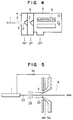
- the second system is, as depicted in FIG. 3 or 4, a method of introducing the ions to an MS part 8 through several-staged differential pumping systems employing a plurality of partition walls formed with the aperture 3 and skimmer(s) 5, 7.
- an aperture diameter d (m) and a pumping speed S (m 3 /s) of a vacuum pump are given as follows to obtain a vacuum required for the MS.
- a vacuum degree for operation of the MS is herein 10 -3 - 10 -4 Pa.
- a conductance C 1 of a gas in viscous flow region of the aperture diameter d (m) is obtained by the formula (1).
- the vacuum P 1 of the MS part is obtained by the formula (2).
- the atmospheric pressure P 0 is approximately 10 5 Pa.
- P 1 C 1 (P 0 - P 1 )/S 1
- the aperture has a diameter of approximately 2.5 ⁇ m. If a cryopump having a pumping speed of 10,000 liters/s is employed as the vacuum pump, the aperture diameter is nothing more than 7.9 ⁇ m. When the ions are sampled from the atmosphere through the aperture having such a small diameter clogging of the aperture is frequently caused due to matters such as dusts in the air. Further, since the diameter of the aperture is small, a good deal of ions can not be introduced. This makes the high sensitivity measurement difficult. An additional problem is that the cryopump is remarkably expensive.
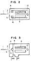
- FIG. 2 is a schematic diagram based on this system. The ions sprayed from a spray nozzle 1 and generated under an atmospheric pressure and in a high electrostatic field 2 enter the MS part via the aperture 3. Neutral molecules are trapped by a cooling fin 16 of the cryopump. On the other hand, the ions go straight and undergo a mass sorting in a quadrupole MS 9 and reach a detector 10.
- the vacuum of the MS unit 8 is defined as follows. Let P 0 be the atmospheric pressure, and let P 2 be the vacuum degree of the MS unit 8. Let S 1 , S 2 be the pumping speeds of the vacuum pumps of the differential pumping system part and MS part, respectively. Let C 1 , C 2 be the conductances of gases of the first and second apertures 3, 5, respectively. Further, let d 1 , d 2 be the diameters of the first and second apertures.
- C 1 157d 1 2
- the MS part 8 is evacuated by the oil diffusion pump having a pumping speed of 1,000 liters/s, while the differential vacuum system part 4 is evacuated by a mechanical booster pump of 16.7 liters/s.
- the diameter of the first aperture 3 is assumed to be 200 ⁇ m, while the diameter of the second aperture 5 is assumed be 400 ⁇ m.
- the vacuum of the MS part 8 is high enough for the mass analysis.
- the second system using a plurality of apertures and the differential pumping system exhibits such an advantage that the large apertures and the inexpensive vacuum pumps can be utilized. For this reason, the second system is widely utilized in a great number of vacuum devices.
- a 3-stage differential pumping system is similarly utilized. This differential pumping system corresponds to a method which is excellent in terms of such a point that the ions generated under the atmospheric pressure are led to the MS part at a high efficiency.
- the two-or three-stage differential pumping system is used in the LC/MS.
- the cluster ion is an ion to which a multiplicity of polar molecules are added.
- the type and the number of the molecules to be added are not constant. It is therefore impossible to directly obtain the information on a molecular weight of the sample molecule from the cluster ion by means of the MS.
- ions having same m/z are distributed widely in the form of a multiplicity of cluster ions, and hence a detected ionic current value is also decreased. Therefore, desolvation for removing the added molecules from the cluster ions is required.
- Proposed as a method therefor are the following methods and a combinational system thereof. In any case, an external energy greater than the addition energy of the polar molecules is given to the cluster ion, thereby releasing the polar molecules from the ion.
- the energy imparted to the cluster ion is controlled to exceed slightly the energy that is required for the release of the added molecules. It is required that the energy be repeatedly injected into the ions.
- FIG. 5 is a schematic diagram showing this system.
- the cluster ions are made to pass through an inert gas which has been heated ( ⁇ 70°C), e.g., dry nitrogen.
- Nitrogen molecules are caused to collide with the cluster ions, and the heat is transferred to the cluster ions from the nitrogen molecules continually, thereby releasing the added molecules from the ions.
- the dry nitrogen is flowed in a direction 24 opposite to a flow of the ions in the vicinity of the ion sampling aperture 3. Therefore, neutral solvent molecules (such as water) flowing together with the ions are flowed back in a direction 23 opposite to the ions sampling aperture 3 due to the dry nitrogen.
- the ions 22 are accelerated by an electric potential applied between the aperture 3 and the spray nozzle 1 and collide with the dry nitrogen molecules.
- the ions 22 undergo the desolvation and enter the aperture 3. This also prevents extra polar molecule from entering the vacuum chamber, and a possibility of collision and recoupling within the vacuum chamber can be made low.
- this system is a preferable method capable of restricting the polar molecules from entering the vacuum chamber. Hence, the desolvation is attainable more efficiently in a combination with the following system than used singly.
- the Mach disk is generated in a place positioned 6.3 mm away from the aperture towards the high vacuum part.
- the adiabatic compression is effected on the Mach disk surface, whereby the cluster ions are rapidly heated.
- the desolvation is performed.
- the second aperture 5 is disposed in a place positioned 7 mm or more apart backwards from the first aperture 3
- the cluster ions invariably pass through the Mach disk surface, thereby promoting the desolvation with heating by the adiabatic compression.
- This system is a preferable method capable of attaining the desolvation without supply of special external energy. In rear of the Mach disk, however, the flow of molecules becomes absolutely irregular, and the flow of ions entering the second aperture does not become constant.
- sampling is often effected in a molecular flow region (Silent Zone) 27 in front of the Mach disk where the ions and gas molecules continue their motion in straight line.
- Silent Zone molecular flow region
- the gas diffused into the vacuum from the atmospheric pressure is rapidly cooled by the adiabatic expansion.
- the gas to be introduced is heated beforehand, and where the interface including the aperture is heated, the adiabatic cooling can be compensated to some extent, and an addition of water and the like can be prevented. It is, however, difficult to attain the perfect desolvation only by heating. It is because most of ions of organic compounds passing through this interface tend to easily undergo the thermal decomposition by heating. It is therefore impossible to perform heating at a high temperature for the purpose of the desolvation.
- a mean free path of the gaseous molecules become about 0.06 to 0.6 mm.
- the ions existing in the gas are accelerated in a direction along the electric field and collide with the neutral molecules.
- the acceleration and collision are repeated.
- the mean free path is 0.1 mm ( ⁇ 66 Pa)
- the ions are accelerated by approximately 1 eV in the electric field of 100 V/cm, where e is the number of electric valences of the ions. A part of this kinetic energy is transformed into an internal energy (thermal energy) by the collision.
- Important factors in this desolvation system are a vacuum degree and an intensity of the electric field in the case of the acceleration and collision.
- the electric potential is applied between the first and second apertures 3, 5 or/and between the second and third apertures 5, 7, whereby the ions are accelerated and collide with the neutral molecules.
- a degree of the desolvation can be changed by controlling the applied voltages V 1 , V 2 . This method is remarkably effective in the desolvation.
- This method has a defect of directly undergoing influences of the pressures of the ion acceleration and collision parts 4, 6. Besides, because of accelerating the ions, there is a risk in which a part of the kinetic energy is not consumed by the collision but is imparted directly to the ions. Therefore, the ions which have entered the high vacuum MS part 8 spread in speed. It follows that this directly brings about declines in resolving power and sensitivity in the mass analysis. If the speed spread exceeds 1 eV, it is difficult to attain the resolving power more than one mass unit in the case of the quadrupole MS. In addition, a transmissivity of the ions is also decreased. In the case of a double focusing mass spectrometer, the large energy dispersion occurs due to the electric field, with the result that the declines in the sensitivity and resolving power are induced.
- the mean free path of the nitrogen molecules under pressures from the atmospheric pressure ( ⁇ 10 5 Pa) to 10 3 Pa is approximately 5 ⁇ 10 -5 mm - 5 ⁇ 10 -3 mm. Even when the electric field of 100 V/mm is applied under these pressures, the kinetic energy received by the ions ranges from 5 ⁇ 10 -3 eV to 5 ⁇ 10 -1 eV, which is considerably lower than 1 eV. The collisions frequently happen in this pressure region, and it is therefore impossible to accelerate the ions, although the ion moving direction can be changed even when the electric field is applied. More specifically, even when the ions are accelerated under this pressure, the spread of the kinetic energy can be restrained not more than 1 eV.
- the mean free path of the nitrogen molecules ranges from approximately 5 ⁇ 10 -3 mm to 5 mm.
- the electric field of 100 V/mm is applied under this pressure, the kinetic energy received by the ions within the mean free path is as large as 5 ⁇ 10 -1 eV to 5 ⁇ 10 2 eV. This causes a large spread of the kinetic energy (speed).
- the mean free path becomes 50 mm to 50 m. Reduced is a probability that the accelerated ions collide with the neutral molecules in the acceleration field. The spread of the kinetic energy is reduced.
- the vacuum gradually becomes higher from the ions sampling aperture 3 in the ion flying direction of the MS part 8. If there is a sufficient space between the ions sampling aperture 3 and an ion acceleration electrode 20, the ions are accelerated between these two portions and invariably pass through the intermediate pressure region (10 3 Pa - 1 Pa). Spread of energies of the ions do not occur in the high pressure part (10 5 - 10 3 Pa). On the other hand, the ions are accelerated in the region where the pressure ranges from 10 2 Pa to 1 Pa, and the energy spread is provided.
- the ion acceleration electrode 20 In order to restrain the energy (speed) spread as low as possible, the ion acceleration electrode 20 is positioned close to the ion sampling aperture 3, and the ions are accelerated in the high pressure part (10 5 - 10 3 Pa). In this region, however, the cluster ions can not be sufficiently accelerated. The energy required for the desolvation cannot be given to the cluster ions. Therefore, the desolvation in this region can not be expected.
- the ion acceleration in the differential pumping system part is an acceleration in the intermediate pressure region (10 3 - 1 Pa), and it follows that the energy spread is imparted.
- the following prevention measures are required for avoiding this energy spread.
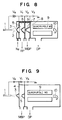
- the pressure difference is controlled stepwise and accurately by using a plurality of differential pumping system. Further, the desolvation by acceleration is performed in the vacuum of 10 2 Pa or under, and the ion acceleration is restrained at the possible lowest level under the intermediate pressure of 10 2 - 1 Pa. The ions are accelerated at a stretch in the next high vacuum region. This requires a difficult of the pressure control and an intricate and expensive differential pumping system as shown in FIG. 8.
- the pressure of the first vacuum chamber 4 is kept at 10 3 - 10 2 Pa, while the ion acceleration voltage V 1 is kept at 100 - 200 V.
- the second vacuum chamber is maintained at 10 - 1 Pa, while the ion acceleration voltage V 2 is restrained down at 10 - 20 V.
- the collision dissociation is promoted by increasing the ion acceleration voltage in such a low vacuum region as to exert no influence on the ion speed. Whereas in such a region as to exert an influence on the ion speed, the ion acceleration voltage is restrained low. It is not, however, easy to constantly control the pressure and the ion acceleration voltage.
- the present invention is embodied by the following technique.
- the intermediate vacuum region (10 2 - 1 Pa) between the case of the high pressure and the case of high vacuum, the spread of speed is induced.
- the intermediate vacuum region is physically separated from each of the high-pressure part and high-vacuum part through partition walls with orifices.
- the voltage required for accelerating the ions is applied in each vacuum chamber. Chambers are provided so that the interface parts are depressurized sequentially from the atmospheric pressure.
- the chamber adjacent to the atmospheric pressure is evacuated not by an independent pump but through a bypass hole opened to the high vacuum part at the next stage, so that a pressure of this chamber can be easily set by a conductance of this hole.
- the vacuum pump, the pumping duct and the control power supply of vacuum system can be thereby simplified.
- the ions are accelerated by the electric field of 200 through 100 V/ 5 mm in the chamber held at a pressure of 10 3 to 10 2 Pa. It is therefore possible to provide the number of collisions and energy required for the desolvation while restraining the energy spread within 1 eV.
- An electric potential (approximately 10-20 V/5 mm) enough to converge the ions is given in the chamber of 10 2 to 1 Pa. The energy spread in this region can be thereby restrained within 12 eV.
- an ESI Electro-Spray Ionization, i.e., ionization by spraying a liquid in a high electric field
- a spray nozzle 1 to which a high voltage V 0 is applied
- a counter gas introduction chamber 25 a first aperture (ion sampling aperture) 3, a first vacuum chamber 4, a second aperture 5, a second vacuum chamber 6, a third aperture 7, an ion acceleration power supply 21, a heater 14 and a heater power supply 15.
- An eluate fed in from the LC reaches the spray nozzle 1 and is sprayed in the atmosphere 2.
- a good deal of electric charges are carried on the sprayed droplet surfaces.
- the droplets are diminished by evaporating the solvent from the droplet surfaces while flying in the atmosphere 2.
- a repulsion of the electric charges of the same polarity carried on the surface becomes greater than a surface tension, the droplets are segmented at a stretch. Finally, it comes to a result that the ions have evaporated from the liquid phase to the atmosphere 2 (gas phase).
- the counter gas is made to flow into the atmosphere 2 from the vicinity of the first aperture 3 in a direction opposite to the flying direction of the ions, where the counter gas is fed via a needle valve 12 from a gas cylinder 13.
- the counter gas is typically heated at 60 - 70°C, thus promoting the evaporation of the solvent from the droplets.
- the ions move with the aid of the electric field while resisting a flow of the counter gas and enter the first vacuum chamber 4 via the first aperture 3.
- the ions are then accelerated by the voltage V 1 applied between the partition walls, of the first vacuum chamber, formed respectively with the first and second apertures 3, 5.
- the ions then collide with the neutral gaseous molecules and undergo the desolvation.
- the ions further enter the second vacuum chamber 6 via the second aperture 5.
- the ions are herein subjected to an acceleration and convergence and enter the third aperture 7.
- the ions, which have entered the MS part 8 via the third aperture 7, are accelerated by an acceleration voltage applied between the ion acceleration electrode 20 and the third aperture 7 as well.
- the ions then undergo a mass sorting by the quadrupole MS 9.
- the ions are detected by the detector 10 and provides a mass spectrum after passing through a DC amplifier 11.
- the first, second and third apertures typically have a skimmer structure, whereby the diffused neutral molecules are prevented from entering the next vacuum chamber.
- the first vacuum chamber 4 includes no independent vacuum pump and is structured such that this chamber 4 is evacuated by the vacuum pump 1 through the second vacuum chamber 6 from a bypass hole 26 provided downwardly of the second aperture 5.
- the MS part is evacuated by an independent vacuum pump 2.
- Numeral 9 designates a quadrupole, and 21 denotes an ion acceleration power supply.
- the interface part is heated by the heater power supply 15 and the heater 14 to prevent cooling due to the adiabatic expansion.
- the diameters of the first, second and third apertures are 200 ⁇ m, 400 ⁇ m and 500 ⁇ m, respectively; and the diameter of the bypass hole formed downwardly of the second aperture is 5 mm. It is also presumed that the pumping speeds of the vacuum pumps 1, 2 are 16.7 liters/s and 1,000 liters/s.
- P 1 , P 2 , P 3 be the vacuum degrees of the firs vacuum chamber, the second vacuum chamber and the MS part.
- the vacuum obtained in the second vacuum chamber is better than in the first vacuum chamber by approximately one digit.
- the system is equivalent to the 2-stage differential pumping system shown in the vacuum system diagram of FIG. 8. Namely, the system is equivalent to a 3-stage differential pumping system including an oil rotary pump (pumping speed: 120 liters/m), a mechanical booster pump (pumping speed: 1,000 liters/m) and an oil diffusion pump (pumping speed: 1,000 liters/s).
- the oil rotary pump, pumping ducts and a vacuum sequence controller are unnecessary, thereby remarkably simplifying the vacuum system.
- the acceleration by the ion acceleration voltage V 1 of 100 V is effected.
- FIG. 10 shows an example where the first vacuum chamber 4 is evacuated only via the second aperture 5. If the diameter of the second aperture is set from several mm to approximately 5 mm, the situation is equivalent to that in the embodiment of FIG. 1.
- FIG. 11 Another embodiment of the present invention is shown by FIG. 11. Ion sampling is carried out not by the apertures but by a capillary (inside diameter: 0.5 - 0.2 m, length: 100 mm - 200 mm).
- the capillary may be made of quartz or metallic material such as stainless steel. In the case of quartz, however, it is required that the ion accelerating electric potential be applicable by effecting silver plating or the like on both ends thereof. Besides, it is possible to help the desolvation by heating this capillary.
- the point that the first vacuum chamber is evacuated by the pump 1 via the bypass hole 26 is the same as the embodiment 1.
- FIG. 12 shows an insulin (molecular weight: 5734.6) mass spectrum obtained by the conventional system illustrate in FIG. 9.
- a quantity of introduced sample was 1 ⁇ g.
- Significant peaks (multiply charged ion) do not appear on the mass spectrum.
- This measurement involved the use of a double focusing mass spectrometer, wherein the accelerating voltage was 4 kV.
- FIG. 13 shows a bovine insulin mass spectrum obtained by the embodiment (FIG. 1) according to the present invention.
- a quantity of introduced sample was 10 ng.
- insulin's multiply charged ions M + 6H) 6+ , (M + 5H) 5+ , and (M + 4H) 4+ .
- the desolvation was imperfect in the foregoing system, and the multiply charged ions irregularly appear as noises in a wide mass region or captured by the electric field of the double focusing mass spectrometer.
- the desolvation of the multiply charged ions was sufficiently performed, and the mass peak is obviously given onto the mass spectrum. Further, the noises on the mass spectrum due to the cluster ions are reduced.
- the multiply charged ions and peusomolecular ions are subjected the sufficient desolvation, and the measurement can be performed with a high sensitivity.
- the electro-spray ionization has been exemplified as the atmospheric pressure ionization.
- the same effects are, however, obtainable by atmospheric pressure chemical ionization (APCI), pneumatically assisted ESI and the like.
- APCI atmospheric pressure chemical ionization
- the present invention is applied not only to the LC/MS but to methods of ionization under the atmospheric pressure as in the case of supercritical fluid chromatography (SFC)/MS and CZE (Capillary Zone Electrophoresis)/MS.
- the differential pumping system is simplified, and the inexpensive device can be provided.
Landscapes
- Chemical & Material Sciences (AREA)
- Analytical Chemistry (AREA)
- Other Investigation Or Analysis Of Materials By Electrical Means (AREA)
- Electron Tubes For Measurement (AREA)
Claims (9)
- Procédé de spectrométrie de masse comprenant les étapes consistant à:générer des ions sous une pression atmosphérique,mettre sous vide de chambres à vides faible et intermédiaire (4, 6) à l'aide d'un système de vide commun, de telle sorte que le vide de la première soit inférieur à celui de la dernière,amener les ions générés (22) dans une chambre à vide élevé (8) ayant un vide supérieur à celui desdites chambres à vides faible et intermédiaire (4, 6) par l'intermédiaire desdites chambres à vides faible et intermédiaire, eteffectuer une analyse de masse dans ladite chambre à vide élevé (8).
- Procédé selon la revendication 1, dans lequel ladite chambre à vide faible (4) est mise sous vide par ledit système de vide (26, 1) par l'intermédiaire de ladite chambre à vide intermédiaire (6).
- Procédé selon la revendication 1 ou 2, comprenant de plus l'étape consistant à accélérer les ions dans ladite chambre à vide faible (4) par une première tension d'accélération (V1) et dans ladite chambre de vide intermédiaire (6) par une deuxième tension d'accélération (V2) qui est inférieure à la première tension d'accélération.
- Interface pour un spectromètre de masse, pour une disposition entre des moyens (1) pour générer des ions à la pression atmosphérique et des moyens (9, 10) pour effectuer une analyse de masse des ions sous un vide élevé, comprenant des première et deuxième chambres à vide (4, 6) et des moyens (1) pour mettre sous vide lesdites chambres à vide de telle sorte que le vide de la première soit inférieur à celui de la dernière, dans laquelle lesdites première et deuxième chambres à vide (4, 6) comprennent des ouvertures (3, 5) disposées de façon à permettre aux ions de traverser lesdites première et deuxième chambres à vide, lesdits moyens de mise sous vide (1) étant communs auxdites première et deuxième chambres à vide.
- Interface selon la revendication 4, dans laquelle au moins l'une desdites ouvertures (3, 5) a une configuration en écumoire.
- Interface selon la revendication 4 ou 5, comprenant de plus des moyens pour accélérer les ions dans ladite première chambre à vide (4) à l'aide d'une première tension d'accélération (V1) et dans ladite deuxième chambre à vide (6) à l'aide d'une deuxième tension d'accélération (V2) qui est inférieure à ladite première tension d'accélération.
- Interface selon l'une quelconque des revendications 4 à 6, comprenant de plus un trou de pompage de dérivation (26) à travers lequel ladite première chambre à vide (4) communique avec ladite deuxième chambre à vide (6), de telle sorte que ladite première chambre à vide (4) soit mise sous vide par lesdits moyens de mise sous vide (1) par l'intermédiaire de ladite deuxième chambre à vide (6).
- Interface selon l'une quelconque des revendications 4 à 7, comprenant de plus des moyens (25) pour introduire un gaz inerte à l'opposé de la direction d'écoulement des ions, au voisinage de l'ouverture (3) de ladite première chambre à vide (4).
- Spectromètre de masse comprenant des moyens (1) pour générer des ions à la pression atmosphérique, des moyens (9, 10) pour effectuer une analyse de masse des ions sous un vide élevé, et une interface selon l'une quelconque des revendications 4 à 8 pour interconnecter lesdits deux moyens, dans lequel ladite deuxième chambre à vide (6) est disposée entre ladite première chambre à vide (4) et lesdits moyens d'analyse de masse (9, 10).
Applications Claiming Priority (2)
| Application Number | Priority Date | Filing Date | Title |
|---|---|---|---|
| JP3232956A JP2913924B2 (ja) | 1991-09-12 | 1991-09-12 | 質量分析の方法および装置 |
| JP232956/91 | 1991-09-12 |
Publications (2)
| Publication Number | Publication Date |
|---|---|
| EP0532046A1 EP0532046A1 (fr) | 1993-03-17 |
| EP0532046B1 true EP0532046B1 (fr) | 1997-12-10 |
Family
ID=16947503
Family Applications (1)
| Application Number | Title | Priority Date | Filing Date |
|---|---|---|---|
| EP92115612A Expired - Lifetime EP0532046B1 (fr) | 1991-09-12 | 1992-09-11 | Spectrometre de masse à ionisation en pression atmosphérique et dispositif à vide adapté |
Country Status (4)
| Country | Link |
|---|---|
| US (2) | US5298743A (fr) |
| EP (1) | EP0532046B1 (fr) |
| JP (1) | JP2913924B2 (fr) |
| DE (1) | DE69223471T2 (fr) |
Families Citing this family (30)
| Publication number | Priority date | Publication date | Assignee | Title |
|---|---|---|---|---|
| US5304798A (en) * | 1992-04-10 | 1994-04-19 | Millipore Corporation | Housing for converting an electrospray to an ion stream |
| DE4322102C2 (de) * | 1993-07-02 | 1995-08-17 | Bergmann Thorald | Flugzeit-Massenspektrometer mit Gasphasen-Ionenquelle |
| GB9324213D0 (en) * | 1993-11-25 | 1994-01-12 | Kore Tech Ltd | Vacuum inlet |
| US5495107A (en) * | 1994-04-06 | 1996-02-27 | Thermo Jarrell Ash Corporation | Analysis |
| DE4415480C2 (de) * | 1994-05-02 | 1999-09-02 | Bruker Daltonik Gmbh | Vorrichtung und Verfahren zur massenspektrometrischen Untersuchung von Substanzgemischen durch Kopplung kapillarelektrophoretischer Separation (CE) mit Elektrospray-Ionisierung (ESI) |
| DE19520276C2 (de) * | 1995-06-02 | 1999-08-26 | Bruker Daltonik Gmbh | Vorrichtung für die Einführung von Ionen in ein Massenspektrometer |
| DE19523860A1 (de) * | 1995-06-30 | 1997-01-02 | Bruker Franzen Analytik Gmbh | Ionenfallen-Massenspektrometer mit vakuum-externer Ionenerzeugung |
| US5672868A (en) * | 1996-02-16 | 1997-09-30 | Varian Associates, Inc. | Mass spectrometer system and method for transporting and analyzing ions |
| DE69824586T2 (de) * | 1997-06-26 | 2005-06-23 | PerSeptive Biosystems, Inc., Framingham | Probenträger hoher dichte für die analyse biologischer proben |
| US6122050A (en) * | 1998-02-26 | 2000-09-19 | Cornell Research Foundation, Inc. | Optical interface for a radially viewed inductively coupled argon plasma-Optical emission spectrometer |
| JP3581604B2 (ja) * | 1999-09-13 | 2004-10-27 | 株式会社日立製作所 | 大気圧イオン化質量分析装置 |
| US6528784B1 (en) * | 1999-12-03 | 2003-03-04 | Thermo Finnigan Llc | Mass spectrometer system including a double ion guide interface and method of operation |
| JP2002124208A (ja) * | 2000-08-10 | 2002-04-26 | Anelva Corp | 質量分析のイオン化方法および質量分析装置 |
| US20020115056A1 (en) * | 2000-12-26 | 2002-08-22 | Goodlett David R. | Rapid and quantitative proteome analysis and related methods |
| US7405397B2 (en) * | 2002-03-28 | 2008-07-29 | Mds Sciex Inc. | Laser desorption ion source with ion guide coupling for ion mass spectroscopy |
| GB0305796D0 (en) | 2002-07-24 | 2003-04-16 | Micromass Ltd | Method of mass spectrometry and a mass spectrometer |
| US7015466B2 (en) * | 2003-07-24 | 2006-03-21 | Purdue Research Foundation | Electrosonic spray ionization method and device for the atmospheric ionization of molecules |
| US7259371B2 (en) * | 2005-01-10 | 2007-08-21 | Applera Corporation | Method and apparatus for improved sensitivity in a mass spectrometer |
| US7256395B2 (en) * | 2005-01-10 | 2007-08-14 | Applera Corporation | Method and apparatus for improved sensitivity in a mass spectrometer |
| US20070095726A1 (en) * | 2005-10-28 | 2007-05-03 | Tihiro Ohkawa | Chafftron |
| GB0609253D0 (en) * | 2006-05-10 | 2006-06-21 | Micromass Ltd | Mass spectrometer |
| US8288719B1 (en) * | 2006-12-29 | 2012-10-16 | Griffin Analytical Technologies, Llc | Analytical instruments, assemblies, and methods |
| GB2489623B (en) * | 2007-09-07 | 2013-03-06 | Ionics Mass Spectrometry Group | Multi-pressure stage mass spectrometer and methods |
| US8373118B2 (en) * | 2010-10-21 | 2013-02-12 | Advion, Inc. | Atmospheric pressure ionization inlet for mass spectrometers |
| AU2011334612A1 (en) * | 2010-11-26 | 2013-05-02 | Bruker Chemical Analysis Bv | Improvements in or relating to mass spectrometry |
| EP2660590A1 (fr) * | 2010-12-27 | 2013-11-06 | Shiseido Co., Ltd. | Procédé de spectrométrie de masse, spectromètre de masse et système de spectrométrie de masse |
| JP5792561B2 (ja) * | 2011-08-25 | 2015-10-14 | 株式会社日立製作所 | 自動クリーニング機能付き質量分析装置 |
| US9368335B1 (en) | 2015-02-02 | 2016-06-14 | Thermo Finnigan Llc | Mass spectrometer |
| WO2020110264A1 (fr) * | 2018-11-29 | 2020-06-04 | 株式会社島津製作所 | Spectromètre de masse |
| CN117355922A (zh) * | 2021-05-26 | 2024-01-05 | 株式会社岛津制作所 | 质量分析装置 |
Family Cites Families (11)
| Publication number | Priority date | Publication date | Assignee | Title |
|---|---|---|---|---|
| US3842266A (en) * | 1973-04-11 | 1974-10-15 | Us Air Force | Atmospheric sampling probe for a mass spectrometer |
| US4209696A (en) * | 1977-09-21 | 1980-06-24 | Fite Wade L | Methods and apparatus for mass spectrometric analysis of constituents in liquids |
| JPS6215747A (ja) * | 1985-07-15 | 1987-01-24 | Hitachi Ltd | 質量分析計 |
| JPS6220231A (ja) * | 1985-07-18 | 1987-01-28 | Seiko Instr & Electronics Ltd | Icp質量分析装置 |
| JPH07118295B2 (ja) * | 1985-10-30 | 1995-12-18 | 株式会社日立製作所 | 質量分析計 |
| US4842701A (en) * | 1987-04-06 | 1989-06-27 | Battelle Memorial Institute | Combined electrophoretic-separation and electrospray method and system |
| JP2753265B2 (ja) * | 1988-06-10 | 1998-05-18 | 株式会社日立製作所 | プラズマイオン化質量分析計 |
| US4963735A (en) * | 1988-11-11 | 1990-10-16 | Hitachi, Ltd. | Plasma source mass spectrometer |
| US4996424A (en) * | 1990-05-03 | 1991-02-26 | Hitachi, Ltd. | Atmospheric pressure ionization mass spectrometer |
| US5015845A (en) * | 1990-06-01 | 1991-05-14 | Vestec Corporation | Electrospray method for mass spectrometry |
| US5157260A (en) * | 1991-05-17 | 1992-10-20 | Finnian Corporation | Method and apparatus for focusing ions in viscous flow jet expansion region of an electrospray apparatus |
-
1991
- 1991-09-12 JP JP3232956A patent/JP2913924B2/ja not_active Expired - Fee Related
-
1992
- 1992-09-10 US US07/942,992 patent/US5298743A/en not_active Expired - Lifetime
- 1992-09-11 DE DE69223471T patent/DE69223471T2/de not_active Expired - Lifetime
- 1992-09-11 EP EP92115612A patent/EP0532046B1/fr not_active Expired - Lifetime
-
1997
- 1997-04-18 US US08/841,002 patent/US5744798A/en not_active Expired - Lifetime
Also Published As
| Publication number | Publication date |
|---|---|
| JPH0574409A (ja) | 1993-03-26 |
| US5744798A (en) | 1998-04-28 |
| DE69223471T2 (de) | 1998-07-16 |
| JP2913924B2 (ja) | 1999-06-28 |
| DE69223471D1 (de) | 1998-01-22 |
| US5298743A (en) | 1994-03-29 |
| EP0532046A1 (fr) | 1993-03-17 |
Similar Documents
| Publication | Publication Date | Title |
|---|---|---|
| US5298743A (en) | Mass spectrometry and mass spectrometer | |
| US6087657A (en) | Mass spectrometry and mass spectrometer | |
| US4542293A (en) | Process and apparatus for changing the energy of charged particles contained in a gaseous medium | |
| US5432343A (en) | Ion focusing lensing system for a mass spectrometer interfaced to an atmospheric pressure ion source | |
| US4091655A (en) | Method and apparatus for analyzing trace components using a cryopumpable reagent gas | |
| EP0644796B1 (fr) | Interface ionique a pression atmospherique pour un analyseur de masses | |
| US4531056A (en) | Method and apparatus for the mass spectrometric analysis of solutions | |
| US6812459B2 (en) | Ion sampling for APPI mass spectrometry | |
| US5756994A (en) | Electrospray and atmospheric pressure chemical ionization mass spectrometer and ion source | |
| US4667100A (en) | Methods and apparatus for mass spectrometric analysis of fluids | |
| WO2004026448A1 (fr) | Source d'ionisation a modes multiples | |
| JPH0785834A (ja) | 質量分析計および静電レンズ | |
| CA2162856A1 (fr) | Methode pour l'analyse de la masse plasmatique avec effet de charge spatiale reduit | |
| GB2309580A (en) | Method and apparatus for plasma mass analysis with reduced space charge effects | |
| US5331159A (en) | Combined electrospray/particle beam liquid chromatography/mass spectrometer | |
| US6344646B1 (en) | Ion trap mass spectrometer and ion trap mass spectrometry | |
| JP2018040794A (ja) | 質量分析のためのイオン輸送装置 | |
| US7230234B2 (en) | Orthogonal acceleration time-of-flight mass spectrometer | |
| US5164593A (en) | Mass spectrometer system including an ion source operable under high pressure conditions, and a two-stage pumping arrangement | |
| EP0444896A2 (fr) | Source d'ions par nébulisation thermique à flux de vapeurs coaxial avec un seul orifice | |
| JPH07260765A (ja) | 質量分析装置 | |
| EP0627758A2 (fr) | Dispositif de spectrométrie de masse | |
| JP3559736B2 (ja) | 質量分析計 | |
| JPH10112281A (ja) | 質量分析の方法および装置 | |
| US12203886B2 (en) | Ion analyzer |
Legal Events
| Date | Code | Title | Description |
|---|---|---|---|
| PUAI | Public reference made under article 153(3) epc to a published international application that has entered the european phase |
Free format text: ORIGINAL CODE: 0009012 |
|
| AK | Designated contracting states |
Kind code of ref document: A1 Designated state(s): DE FR GB |
|
| 17P | Request for examination filed |
Effective date: 19930903 |
|
| 17Q | First examination report despatched |
Effective date: 19950222 |
|
| GRAG | Despatch of communication of intention to grant |
Free format text: ORIGINAL CODE: EPIDOS AGRA |
|
| GRAH | Despatch of communication of intention to grant a patent |
Free format text: ORIGINAL CODE: EPIDOS IGRA |
|
| GRAH | Despatch of communication of intention to grant a patent |
Free format text: ORIGINAL CODE: EPIDOS IGRA |
|
| GRAA | (expected) grant |
Free format text: ORIGINAL CODE: 0009210 |
|
| AK | Designated contracting states |
Kind code of ref document: B1 Designated state(s): DE FR GB |
|
| PG25 | Lapsed in a contracting state [announced via postgrant information from national office to epo] |
Ref country code: FR Free format text: LAPSE BECAUSE OF FAILURE TO SUBMIT A TRANSLATION OF THE DESCRIPTION OR TO PAY THE FEE WITHIN THE PRESCRIBED TIME-LIMIT Effective date: 19971210 |
|
| REF | Corresponds to: |
Ref document number: 69223471 Country of ref document: DE Date of ref document: 19980122 |
|
| EN | Fr: translation not filed | ||
| PLBE | No opposition filed within time limit |
Free format text: ORIGINAL CODE: 0009261 |
|
| 26N | No opposition filed | ||
| REG | Reference to a national code |
Ref country code: GB Ref legal event code: IF02 |
|
| PGFP | Annual fee paid to national office [announced via postgrant information from national office to epo] |
Ref country code: GB Payment date: 20100902 Year of fee payment: 19 |
|
| PGFP | Annual fee paid to national office [announced via postgrant information from national office to epo] |
Ref country code: DE Payment date: 20100728 Year of fee payment: 19 |
|
| GBPC | Gb: european patent ceased through non-payment of renewal fee |
Effective date: 20110911 |
|
| REG | Reference to a national code |
Ref country code: DE Ref legal event code: R119 Ref document number: 69223471 Country of ref document: DE Effective date: 20120403 |
|
| PG25 | Lapsed in a contracting state [announced via postgrant information from national office to epo] |
Ref country code: DE Free format text: LAPSE BECAUSE OF NON-PAYMENT OF DUE FEES Effective date: 20120403 |
|
| PG25 | Lapsed in a contracting state [announced via postgrant information from national office to epo] |
Ref country code: GB Free format text: LAPSE BECAUSE OF NON-PAYMENT OF DUE FEES Effective date: 20110911 |