EP0532105B1 - Staubabscheider - Google Patents
Staubabscheider Download PDFInfo
- Publication number
- EP0532105B1 EP0532105B1 EP92202715A EP92202715A EP0532105B1 EP 0532105 B1 EP0532105 B1 EP 0532105B1 EP 92202715 A EP92202715 A EP 92202715A EP 92202715 A EP92202715 A EP 92202715A EP 0532105 B1 EP0532105 B1 EP 0532105B1
- Authority
- EP
- European Patent Office
- Prior art keywords
- gas
- centrifuge
- dust separator
- filter
- chamber
- Prior art date
- Legal status (The legal status is an assumption and is not a legal conclusion. Google has not performed a legal analysis and makes no representation as to the accuracy of the status listed.)
- Expired - Lifetime
Links
Images
Classifications
-
- B—PERFORMING OPERATIONS; TRANSPORTING
- B01—PHYSICAL OR CHEMICAL PROCESSES OR APPARATUS IN GENERAL
- B01D—SEPARATION
- B01D45/00—Separating dispersed particles from gases or vapours by gravity, inertia, or centrifugal forces
- B01D45/12—Separating dispersed particles from gases or vapours by gravity, inertia, or centrifugal forces by centrifugal forces
-
- B—PERFORMING OPERATIONS; TRANSPORTING
- B01—PHYSICAL OR CHEMICAL PROCESSES OR APPARATUS IN GENERAL
- B01D—SEPARATION
- B01D50/00—Combinations of methods or devices for separating particles from gases or vapours
- B01D50/20—Combinations of devices covered by groups B01D45/00 and B01D46/00
Definitions
- the invention relates to a dust separator for separating particles from a gas, provided with a centrifuge which is rotatable about a central axis and with a gas inlet and a gas outlet which are situated upstream and downstream of the centrifuge, respectively, seen in a gas flow direction, said centrifuge comprises at least two concentrically arranged centrifuge chambers, a first centrifuge chamber being connected to the gas inlet at one side and at an opposing other side to a gas reversal chamber which is furthermore connected to a second centrifuge chamber.
- Such a dust separator is known from GB-A-2 176 719 and GB-A-2 128 903.
- the said first centrifuge chamber is the outer centrifuge chamber which is connected to the gas inlet. This means that particles to be separated from the gas first enter the outer centrifuge chamber. The particles are subjected to a radially outward force derived from the gas centrifuge in operation and collected on the wall of the rotating centrifuge chambers and on the stationary wall of the casing surrounding the centrifuge. Most of the heavier particles in the gas flow will move to the wall of the casing and will not enter the centrifuge chamber. In practice not only the centrifuge rotor but also the casing has to be cleaned regularly.
- the centrifuge comprises two spaced tubular parts forming the centrifuge chambers. Without further additional filter means it is in fact not possible to separate small particles in the range of 0.1 to 5 ⁇ m.
- Another disadvantage of this known separator is that the gas flow in the outer centrifuge chamber has to move inward to enter the inner centrifuge chamber, whereas the gasflow is subjected to a radially outward force. This results in more energy consumption.
- a centrifuge comprises a filter which is rotatable about a central axis.
- the filter is provided with channels whose walls extend parallel to the central axis.
- Gas for example air, which is polluted with liquid or solid particles having a diameter of 0.1 to 5 ⁇ m, is guided in axial direction into the channels of the filter through a gas inlet.
- a force in axial direction acts on the dust particles as a result of the gas flow, as well as a centrifugal force in radial direction as a result of the filter rotation.
- the centrifugal force presses the dust particles against the walls of the filter.
- the gas is guided from the dust separator through a gas outlet. Dust particles larger than 10 ⁇ m are removed from the gas beforehand.
- a disadvantage of the known dust separator is that a separate device is used for the removal of coarser dust particles (larger than 10 ⁇ m).
- Another disadvantage of the known dust separator is that the filter does not work effectively at a comparatively small radial distance from the central axis since the centrifugal force acting on the particles there is small.
- the invention has for its object to provide a compact dust separator with which the disadvantages of the known dust separator are avoided, which is economical with respect to energy and which is efficient in removing dust particles of widely differing dimensions.
- this object is achieved in that the second centrifuge chamber concentrically surrounds the first centrifuge chamber and the second centrifuge chamber contains a filter.
- the larger and heavier particles are propelled from the gas by the centrifugal force against walls of the first centrifuge chamber which extend parallel to the central axis.
- These walls may be walls of the filter arranged around the first centrifuge chamber or walls of a drum which encloses the first centrifuge chamber and which can rotate in conjunction with the filter.
- the smaller dust particles experience a smaller centrifugal force owing to their smaller dimensions and mass, which force is insufficient for pressing the dust particles against the walls before these particles have passed through the first centrifuge chamber together with the gas. These dust particles leave the first centrifuge chamber with the gas through a side remote from the gas inlet.
- the gas flow is reverted in axial direction in the gas reversal chamber and guided into the filter of the second centrifuge chamber.
- the walls of the filter have such an interspacing that a laminar flow arises in the filter.
- the filter is situated at a greater radial distance away from the central axis than the walls of the first centrifuge chamber, and the centrifugal forces exerted on the dust particles are accordingly greater. Since the gas flow between the walls is laminar, the smaller particles are also pressed against the walls of the filter by the centrifugal force before the gas has passed through the filter.
- a compact dust separator is obtained by the concentric arrangement of the centrifuge chambers.
- the centrifuge rotation automatically sucks gas into the first centrifuge chamber and blows it from the dust separator through the second centrifuge chamber.
- An embodiment of the dust separator according to the invention is characterized in that the gas reversal chamber is provided with gas-guiding means which are rotatable together with the centrifuge.
- the gas-guiding means which comprise a ring of blades or a ring of a porous material, promote the reversal of the gas flow, the distribution of the gas over the filter, the introduction of the gas into the filter, and the generation of a laminar flow.
- a further embodiment of the dust separator according to the invention is characterized in that the filter is manufactured from wound corrugated board, the channels present in the corrugated board extending parallel to the central axis.
- corrugated board is meant in this connection a flat cardboard carrier plate with a corrugated cardboard plate fastened to it.
- Such a filter can be manufactured in a simple and inexpensive manner.
- the filter is manufactured from wound foil, a first winding being kept at a distance from a second winding by means of random unevennesses on the foil, while passages are present between the first and the second winding and the unevennesses, which passages extend at least in axial direction.
- the foil may be made of paper, synthetic material, or metal.
- the passages have an irregular cross-section owing to the random unevennesses and also run partly tangentially.
- the filter can be manufactured in a simple and inexpensive manner in that relief patterns or granules are provided in the foil.
- a yet further embodiment of the dust separator according to the invention is characterized in that the unevennesses form part of carbon granules provided on the foil.
- the carbon granules serve to space the windings of the filter apart and to absorb undesirable gases in the gas to be filtered. In this manner, for example, air may be freed from undesirable smells and noxious gases.
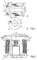
- Fig. 1a shows a dust separator 1 which is provided with a centrifuge 3 which can be rotated about a central axis 5 in a housing by means of a motor.
- the motor and the housing have not been shown for the sake of simplicity.
- the centrifuge 3 comprises a first centrifuge chamber 7 and a second centrifuge chamber 9 which is concentrically arranged around the first centrifuge chamber 7.
- the first centrifuge chamber 7 at one side merges into a gas inlet 11 and at another side into a gas reversal chamber 13.
- the gas reversal chamber 13 in its turn merges into one side of the second centrifuge chamber 9 which at another side merges into a gas outlet 15.
- the second centrifuge chamber 9 comprises a filter 17 which is provided with channels 19 with walls 21 which extend parallel to the central axis 5.
- the channels 19 have a circular cross-section.
- the wall 23 of the filter 17 is at the same time a wall of the first centrifuge chamber 7.
- a ring 25 of porous material is present in the gas reversal chamber 13. The function of this ring 25 will be explained further below.
- the motor (not shown) rotates the centrifuge 3 about the central axis 5 with a speed of, for example, 2.000 rpm. Air is propelled from the gas outlet 15, as a result of which gas, for example air, is sucked into the first centrifuge chamber 7 through the gas inlet 11, which is situated at a smaller diameter than the gas outlet 15.
- the air is carried along with the wall 23 in the centrifuge chamber 7 and made to rotate, so that the dust particles present in the air are subjected to a centrifugal force and are moved towards the wall 23.
- the value of the centrifugal force depends inter alia on the mass of the dust particles.
- Fig. 1b shows a cross-section in the plane A-A of the dust separator 1 according to Fig. 1a.
- the cross-section of a channel may be rectangular or annular instead of circular, or may have any other shape.
- Fig. 2 shows an alternative embodiment of a dust separator according to the invention.
- the parts corresponding to those of Fig. 1 are given the same reference numerals.
- the dust separator 2 comprises a housing 29 in which the centrifuge 3 is accommodated.
- the centrifuge 3 is driven by a motor 31 which is connected to the housing 29 by means of a resilient fastening 28.
- the resilient fastening 28 corresponds to a suspension which is known from centrifuges for the removal of water from laundry.
- the centrifuge 3 is fastened on an output shaft 30 of the motor 31 by known means.
- the gas inlet 11 is provided with a filter 33 which removes coarse dust particles such as, for example, hairs from the air.
- the gas reversal chamber 13 is provided with a blade ring 36 fitted with blades 35 which promotes the suction of air into the dust separator 2 and also reduces turbulences in the air flow, so that a laminar gas flow in the filter 17 is promoted.
- the blades 35 are connected to and rotate along with a wall 37 of the centrifuge 3.
- the flat blades 35 extend in radial direction, the blade surfaces being parallel to the central axis 5. At a greater radial distance from the central axis, the quantity of air to be guided by the blades 35 is smaller than at a smaller radial distance, since at the greater radial distance a portion of the air flow has already been guided into the filter 17.
- the dimension of the blades 35 in axial direction is adapted to the quantity of air to be displaced, and is accordingly smaller at a greater radial distance. This promotes an even distribution of the air flow over the filter.
- Blades 39 are present at the side of the filter 17 facing the gas outlet 15, helping the air to flow out.
- the blades 39 are connected to a bush 40 by means of a number of plates 41, which bush is passed around a portion 42 of the centrifuge 3 and is detachably connected thereto by means of a bolt 44.
- the housing 29 is provided with a detachable lid 43 which has central openings 45 at the gas inlet 11 and openings 47 at the gas outlet 15.
- the filter 33 is present in the lid 43.
- the blades 39 with the plates 41 may be taken as an integral unit from the centrifuge 3.
- the filter 17 may then be removed from the centrifuge 3.
- the filter 17 may be cleaned or replaced by a clean filter.
- the dust separator 2 is of a simple construction and may be readily provided with a clean filter.
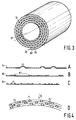
- Fig. 3 shows an embodiment of a filter 17 according to the invention.
- a strip of corrugated board 51 which comprises a flat cardboard carrier plate 53 and a corrugated cardboard plate 55 attached thereto is wound around a core 57 until the diameter corresponds to the desired external diameter of the filter 17.
- the core 57 has a diameter corresponding to the desired internal diameter of the filter 17.
- the channels 19 present in the corrugated board 51 extend parallel to the core 57.
- a thin-walled pipe may alternatively be used, which after winding of the corrugated board around the pipe will form part of the filter.
- Figs. 4a, 4b and 4c show three different strips of material from which filters are wound.
- Fig. 4a shows a paper foil 61 in which relief patterns are provided, for example, by moulding or creasing.
- the foil 61 is rolled around the core 57, the windings are kept at a distance from one another by the projections 63 in the relief pattern.
- Wall paper provided with a relief was found to be suitable as a foil for a filter 17. Such a filter is cheap, easy to manufacture and to replace, and environment-friendly.
- Fig. 4b shows a foil 65 made of aluminium on which granules 67 of any composition (for example, wood chips or plastic) are fastened.
- the granules 67 keep the consecutive windings of the foil 65 at a distance from one another.
- the size of the granules 67 depends on the desired interspacing between the windings. In a dust separator according to the invention, the granule diameter was at most 4 mm.
- the thickness of the foil should be as small as possible (0,1 to 1 mm). No clearly defined channels are formed in the filter by the granules 67, but passages are created in axial direction through the filter which also partly run in tangential direction. Wall paper provided with embedded particles is also suitable as a foil.
- Figs. 4c and 4d show a plastic foil 69 on which carbon granules 71 are provided.
- a foil is suitable for a filter 17 which is used for the removal of an undesirable smell from a gas.
- a smell is mainly caused by a small quantity of a gas mixed in a different gas which is present in a greater quantity.
- the carbon granules 71 absorb the undesirable gas and also keep the different windings 73 of the foil in the filter at a distance from one another. Passages 75 which extend in axial direction are present between the carbon granules 71 and the windings 73.
- the dust separator with a third centrifuge chamber which is situated around the second centrifuge chamber and is connected thereto via a second gas reversal chamber.
- the third centrifuge chamber may be provided with a filter having channels which are smaller than the channels in the filter of the second centrifuge chamber in order to obtain a still better filtering action.
- the blades of the blade ring may alternatively be curved or enclose an angle with the radial planes.
Landscapes
- Chemical & Material Sciences (AREA)
- Chemical Kinetics & Catalysis (AREA)
- Filtering Of Dispersed Particles In Gases (AREA)
- Separating Particles In Gases By Inertia (AREA)
- Centrifugal Separators (AREA)
- Cyclones (AREA)
Claims (9)
- Staubabscheider (1, 2) zum Abscheiden von Teilchen aus einem Gas, mit einer Zentrifuge (3), die um eine zentrale Achse (5) drehbar ist, und mit einem Gaseinlaß (11) und einem Gasauslaß (15), die, in der Gasströmungsrichtung gesehen, vor bzw. hinter der Zentrifuge liegen, wobei die Zentrifuge zumindest zwei konzentrisch angeordnete Zentrifugenkammern (7, 9) umfaßt, wobei eine erste Zentrifugenkammer (7) an einer Seite mit dem Gaseinlaß (11) und an einer gegenüberliegenden anderen Seite mit einer Gasumkehrkammer (13) verbunden ist, die weiterhin mit einer zweiten Zentrifugenkammer (9) verbunden ist, dadurch gekennzeichnet, daß die zweite Zentrifugenkammer (9) die erste Zentrifugenkammer (7) konzentrisch umgibt und die zweite Zentrifugenkammer (9) einen Filter (17) enthält.
- Staubabscheider nach Anspruch 1, dadurch gekennzeichnet, daß die Gasumkehrkammer (13) mit Gasleitungsmitteln (25, 35/36) versehen ist, die zusammen mit der Zentrifuge drehbar sind.
- Staubabscheider nach Anspruch 2, dadurch gekennzeichnet, daß die Gasleitungsmittel (13) einen Ring aus Schaufeln (35/36) umfaßt.
- Staubabscheider nach Anspruch 2, dadurch gekennzeichnet, daß die Gasleitungsmittel einen Ring aus porösem Material (25) umfassen.
- Staubabscheider nach Anspruch 1, dadurch gekennzeichnet, daß der Filter (17) aus gewickelter Wellpappe (51) hergestellt ist, wobei die in der Wellpappe vorhandenen Kanäle (19) parallel zur zentralen Achse (5) verlaufen.
- Staubabscheider nach Anspruch 1, dadurch gekennzeichnet, daß der Filter (17) aus gewickelter Folie (61, 65, 69) hergestellt ist, wobei eine erste Wicklung mit Hilfe von auf der Folie vorhandenen willkürlichen Unebenheiten auf Abstand von einer zweiten Wicklung gehalten wird, während zwischen der ersten und der zweiten Wicklung (73) und den Unebenheiten Durchgänge (75) vorhanden sind, welche Durchgänge in axialer Richtung verlaufen.
- Staubabscheider nach Anspruch 6, dadurch gekennzeichnet, daß die Unebenheiten Teil von in der Folie (61) vorhandenen Reliefstrukturen (63) sind.
- Staubabscheider nach Anspruch 6, dadurch gekennzeichnet, daß die Unebenheiten Teil von in der Folie (65) eingebetteten Körnern (67) sind.
- Staubabscheider nach Anspruch 6, dadurch gekennzeichnet, daß die Unebenheiten Teil von auf der Folie (69) vorhandenen Kohlenstoffkörnern (71) sind.
Applications Claiming Priority (2)
| Application Number | Priority Date | Filing Date | Title |
|---|---|---|---|
| EP91202289 | 1991-09-09 | ||
| EP91202289 | 1991-09-09 |
Publications (3)
| Publication Number | Publication Date |
|---|---|
| EP0532105A2 EP0532105A2 (de) | 1993-03-17 |
| EP0532105A3 EP0532105A3 (en) | 1993-04-07 |
| EP0532105B1 true EP0532105B1 (de) | 1996-12-27 |
Family
ID=8207859
Family Applications (1)
| Application Number | Title | Priority Date | Filing Date |
|---|---|---|---|
| EP92202715A Expired - Lifetime EP0532105B1 (de) | 1991-09-09 | 1992-09-08 | Staubabscheider |
Country Status (8)
| Country | Link |
|---|---|
| US (1) | US5221300A (de) |
| EP (1) | EP0532105B1 (de) |
| JP (1) | JPH05200222A (de) |
| BR (1) | BR9203476A (de) |
| DE (1) | DE69216180T2 (de) |
| ES (1) | ES2098438T3 (de) |
| MX (1) | MX9204964A (de) |
| SG (1) | SG44651A1 (de) |
Families Citing this family (19)
| Publication number | Priority date | Publication date | Assignee | Title |
|---|---|---|---|---|
| NL9300651A (nl) * | 1993-04-16 | 1994-11-16 | Romico Hold A V V | Roterende deeltjesscheider met onevenwijdige scheidingskanalen, en een scheidingseenheid. |
| GB9326121D0 (en) * | 1993-12-22 | 1994-02-23 | Philips Electronics Uk Ltd | Apparatus for removing particles from a fluid |
| NL1003157C2 (nl) * | 1996-05-17 | 1997-11-18 | Romico Hold A V V | Roterende deeltjesscheider met hoge afscheidingsgraad. |
| GB9805224D0 (en) * | 1998-03-12 | 1998-05-06 | Philips Electronics Nv | Air filters |
| FR2794806B1 (fr) * | 1999-06-11 | 2002-06-07 | Jean Louis Rico | Procede et dispositif d'alimentation amelioree en air frais d'un moteur a combustion interne |
| US20030031605A1 (en) * | 2001-08-09 | 2003-02-13 | Yang-Chan Lin | Air purifying passage and device |
| USD489794S1 (en) | 2002-07-29 | 2004-05-11 | Media Blast & Abrasives, Inc. | Compressed air delivery manifold |
| USD482828S1 (en) | 2002-07-29 | 2003-11-25 | Media Blast & Abrasives, Inc. | Abrasive media separator |
| USD482827S1 (en) | 2002-07-29 | 2003-11-25 | Media Blast & Abrasives, Inc. | Abrasive media dust collector |
| USD476668S1 (en) | 2002-07-29 | 2003-07-01 | Media Blast & Abrasives, Inc. | Abrasive media delivery device |
| US20040106366A1 (en) * | 2002-08-26 | 2004-06-03 | Robinson Robert A. | Portable pipe restoration system |
| US7008304B1 (en) * | 2004-08-17 | 2006-03-07 | Media Blast & Abrasives, Inc. | Abrasive and dust separator |
| US20060037293A1 (en) * | 2004-08-17 | 2006-02-23 | Storer Ron D | Blast medium pot |
| CA2598142C (en) * | 2005-02-17 | 2013-07-02 | Shell Canada Limited | Method for removing contaminating gaseous components from a natural gas stream |
| US20070202781A1 (en) * | 2006-02-28 | 2007-08-30 | Media Blast & Abrasives, Inc. | Blast media nozzle and nozzle assembly |
| JP5928110B2 (ja) * | 2012-04-09 | 2016-06-01 | アイシン精機株式会社 | サイクロン式オイル分離装置 |
| US9623539B2 (en) | 2014-07-07 | 2017-04-18 | Media Blast & Abrasive, Inc. | Carving cabinet having protective carving barrier |
| KR101606049B1 (ko) * | 2015-07-29 | 2016-03-24 | 신흥정공(주) | 입체필터를 포함하는 원심필터 |
| US20190201828A1 (en) | 2017-12-29 | 2019-07-04 | Media Blast & Abrasive, Inc. | Adjustable abrasive & dust separator |
Family Cites Families (7)
| Publication number | Priority date | Publication date | Assignee | Title |
|---|---|---|---|---|
| US3320727A (en) * | 1965-08-02 | 1967-05-23 | Mitchell Co John E | Portable vacuum cleaning machine |
| DE7727993U1 (de) * | 1977-09-09 | 1978-02-16 | Bauer - Kompressoren Heinz Bauer, 8000 Muenchen | Filterpatrone |
| US4289513A (en) * | 1978-03-27 | 1981-09-15 | The Mead Corporation | Activated sorbtion paper and products produced thereby |
| GB2128903B (en) * | 1982-09-30 | 1986-04-16 | British Nuclear Fuels Ltd | Separating impurities from a gas |
| US4840645A (en) * | 1983-04-15 | 1989-06-20 | Allied-Signal Inc. | Rotary separator with a porous shroud |
| GB2176719B (en) * | 1985-06-24 | 1988-07-06 | British Nuclear Fuels Plc | Improvements in and relating to cleaning of gases |
| NL8700698A (nl) * | 1987-03-25 | 1988-10-17 | Bb Romico B V I O | Roterende deeltjesscheider. |
-
1992
- 1992-08-20 US US07/932,838 patent/US5221300A/en not_active Expired - Fee Related
- 1992-08-28 MX MX9204964A patent/MX9204964A/es unknown
- 1992-09-02 JP JP4260716A patent/JPH05200222A/ja not_active Withdrawn
- 1992-09-08 BR BR929203476A patent/BR9203476A/pt not_active Application Discontinuation
- 1992-09-08 SG SG1996005098A patent/SG44651A1/en unknown
- 1992-09-08 EP EP92202715A patent/EP0532105B1/de not_active Expired - Lifetime
- 1992-09-08 ES ES92202715T patent/ES2098438T3/es not_active Expired - Lifetime
- 1992-09-08 DE DE69216180T patent/DE69216180T2/de not_active Expired - Fee Related
Also Published As
| Publication number | Publication date |
|---|---|
| DE69216180T2 (de) | 1997-06-12 |
| MX9204964A (es) | 1993-03-01 |
| EP0532105A2 (de) | 1993-03-17 |
| EP0532105A3 (en) | 1993-04-07 |
| BR9203476A (pt) | 1993-03-30 |
| JPH05200222A (ja) | 1993-08-10 |
| US5221300A (en) | 1993-06-22 |
| DE69216180D1 (de) | 1997-02-06 |
| ES2098438T3 (es) | 1997-05-01 |
| SG44651A1 (en) | 1997-12-19 |
Similar Documents
| Publication | Publication Date | Title |
|---|---|---|
| US5221300A (en) | Dust separator and filter suitable for use in such a dust separator | |
| US4118207A (en) | Rotating disc particulate separator | |
| US4382804A (en) | Fluid/particle separator unit and method for separating particles from a flowing fluid | |
| JP2005042698A (ja) | クランクケースガスを清浄化する方法 | |
| CA2593491A1 (en) | Rotary gas cyclone separator | |
| EP0180414A3 (de) | Vielstufiger Rotationsstaubsammler | |
| US3993564A (en) | Filtration apparatus | |
| US4268281A (en) | Method of removing particulate contaminants from a gas stream | |
| EP0122795A1 (de) | Filter zum Abscheiden von in einem Fluidum suspendierten Teilchen, zum Beispiel, in einem Gas | |
| JPS5911048B2 (ja) | 回転機械のハウジングのための排気装置 | |
| CN109865371B (zh) | 除尘用过滤装置 | |
| KR100556440B1 (ko) | 다중 사이클론 집진장치 | |
| JPH07298554A (ja) | フィルタ付送風機 | |
| SU1407521A1 (ru) | Высокоскоростной пылеуловитель | |
| RU2106106C1 (ru) | Пылесос и фильтр для пылесоса | |
| CN215628086U (zh) | 一种转炉煤气高效脱水装置 | |
| WO2004041442A1 (en) | Separator | |
| SU906596A1 (ru) | Центробежный пылеотделитель | |
| WO1997040915A3 (en) | Mechanical device for separation of dust particles from exhaust gases | |
| RU2129473C1 (ru) | Центрифуга для разделения жидкой многофазной среды центрограф | |
| SU1388092A1 (ru) | Фильтрующа центрифуга | |
| JP2584758Y2 (ja) | プレートコンパクタのエンジン吸気装置 | |
| SU1695963A1 (ru) | Фильтр дл очистки жидкостей | |
| GB2128903A (en) | Separating impurities from a gas | |
| RU2098167C1 (ru) | Роторный сепарационный аппарат |
Legal Events
| Date | Code | Title | Description |
|---|---|---|---|
| PUAI | Public reference made under article 153(3) epc to a published international application that has entered the european phase |
Free format text: ORIGINAL CODE: 0009012 |
|
| PUAL | Search report despatched |
Free format text: ORIGINAL CODE: 0009013 |
|
| AK | Designated contracting states |
Kind code of ref document: A2 Designated state(s): DE ES FR GB IT |
|
| AK | Designated contracting states |
Kind code of ref document: A3 Designated state(s): DE ES FR GB IT |
|
| 17P | Request for examination filed |
Effective date: 19931005 |
|
| 17Q | First examination report despatched |
Effective date: 19940831 |
|
| GRAH | Despatch of communication of intention to grant a patent |
Free format text: ORIGINAL CODE: EPIDOS IGRA |
|
| GRAH | Despatch of communication of intention to grant a patent |
Free format text: ORIGINAL CODE: EPIDOS IGRA |
|
| GRAA | (expected) grant |
Free format text: ORIGINAL CODE: 0009210 |
|
| AK | Designated contracting states |
Kind code of ref document: B1 Designated state(s): DE ES FR GB IT |
|
| REF | Corresponds to: |
Ref document number: 69216180 Country of ref document: DE Date of ref document: 19970206 |
|
| ITF | It: translation for a ep patent filed | ||
| ET | Fr: translation filed | ||
| REG | Reference to a national code |
Ref country code: ES Ref legal event code: FG2A Ref document number: 2098438 Country of ref document: ES Kind code of ref document: T3 |
|
| PLBE | No opposition filed within time limit |
Free format text: ORIGINAL CODE: 0009261 |
|
| PGFP | Annual fee paid to national office [announced via postgrant information from national office to epo] |
Ref country code: DE Payment date: 19971121 Year of fee payment: 6 |
|
| 26N | No opposition filed | ||
| PGFP | Annual fee paid to national office [announced via postgrant information from national office to epo] |
Ref country code: GB Payment date: 19980901 Year of fee payment: 7 |
|
| PGFP | Annual fee paid to national office [announced via postgrant information from national office to epo] |
Ref country code: ES Payment date: 19980911 Year of fee payment: 7 |
|
| REG | Reference to a national code |
Ref country code: FR Ref legal event code: CD |
|
| PGFP | Annual fee paid to national office [announced via postgrant information from national office to epo] |
Ref country code: FR Payment date: 19980922 Year of fee payment: 7 |
|
| REG | Reference to a national code |
Ref country code: ES Ref legal event code: PC2A |
|
| PG25 | Lapsed in a contracting state [announced via postgrant information from national office to epo] |
Ref country code: DE Free format text: LAPSE BECAUSE OF NON-PAYMENT OF DUE FEES Effective date: 19990701 |
|
| PG25 | Lapsed in a contracting state [announced via postgrant information from national office to epo] |
Ref country code: GB Free format text: LAPSE BECAUSE OF NON-PAYMENT OF DUE FEES Effective date: 19990908 |
|
| PG25 | Lapsed in a contracting state [announced via postgrant information from national office to epo] |
Ref country code: ES Free format text: LAPSE BECAUSE OF NON-PAYMENT OF DUE FEES Effective date: 19990909 |
|
| GBPC | Gb: european patent ceased through non-payment of renewal fee |
Effective date: 19990908 |
|
| PG25 | Lapsed in a contracting state [announced via postgrant information from national office to epo] |
Ref country code: FR Free format text: LAPSE BECAUSE OF NON-PAYMENT OF DUE FEES Effective date: 20000531 |
|
| REG | Reference to a national code |
Ref country code: FR Ref legal event code: ST |
|
| REG | Reference to a national code |
Ref country code: ES Ref legal event code: FD2A Effective date: 20001013 |
|
| PG25 | Lapsed in a contracting state [announced via postgrant information from national office to epo] |
Ref country code: IT Free format text: LAPSE BECAUSE OF NON-PAYMENT OF DUE FEES Effective date: 20050908 |