EP0532151B1 - Luftförderboden mit Protuberanzen - Google Patents
Luftförderboden mit Protuberanzen Download PDFInfo
- Publication number
- EP0532151B1 EP0532151B1 EP92304479A EP92304479A EP0532151B1 EP 0532151 B1 EP0532151 B1 EP 0532151B1 EP 92304479 A EP92304479 A EP 92304479A EP 92304479 A EP92304479 A EP 92304479A EP 0532151 B1 EP0532151 B1 EP 0532151B1
- Authority
- EP
- European Patent Office
- Prior art keywords
- articles
- apertures
- deck plate
- rows
- air
- Prior art date
- Legal status (The legal status is an assumption and is not a legal conclusion. Google has not performed a legal analysis and makes no representation as to the accuracy of the status listed.)
- Expired - Lifetime
Links
- 239000000463 material Substances 0.000 claims abstract description 13
- 239000012530 fluid Substances 0.000 claims description 2
- 238000009825 accumulation Methods 0.000 description 2
- 238000005188 flotation Methods 0.000 description 2
- 239000007788 liquid Substances 0.000 description 2
- 239000002173 cutting fluid Substances 0.000 description 1
- 239000004744 fabric Substances 0.000 description 1
- 229910001385 heavy metal Inorganic materials 0.000 description 1
- 229910052751 metal Inorganic materials 0.000 description 1
- 239000002184 metal Substances 0.000 description 1
- 230000004048 modification Effects 0.000 description 1
- 238000012986 modification Methods 0.000 description 1
Images

Classifications
-
- B—PERFORMING OPERATIONS; TRANSPORTING
- B01—PHYSICAL OR CHEMICAL PROCESSES OR APPARATUS IN GENERAL
- B01J—CHEMICAL OR PHYSICAL PROCESSES, e.g. CATALYSIS OR COLLOID CHEMISTRY; THEIR RELEVANT APPARATUS
- B01J8/00—Chemical or physical processes in general, conducted in the presence of fluids and solid particles; Apparatus for such processes
- B01J8/18—Chemical or physical processes in general, conducted in the presence of fluids and solid particles; Apparatus for such processes with fluidised particles
- B01J8/24—Chemical or physical processes in general, conducted in the presence of fluids and solid particles; Apparatus for such processes with fluidised particles according to "fluidised-bed" technique
- B01J8/44—Fluidisation grids
-
- B—PERFORMING OPERATIONS; TRANSPORTING
- B65—CONVEYING; PACKING; STORING; HANDLING THIN OR FILAMENTARY MATERIAL
- B65G—TRANSPORT OR STORAGE DEVICES, e.g. CONVEYORS FOR LOADING OR TIPPING, SHOP CONVEYOR SYSTEMS OR PNEUMATIC TUBE CONVEYORS
- B65G51/00—Conveying articles through pipes or tubes by fluid flow or pressure; Conveying articles over a flat surface, e.g. the base of a trough, by jets located in the surface
- B65G51/02—Directly conveying the articles, e.g. slips, sheets, stockings, containers or workpieces, by flowing gases
- B65G51/03—Directly conveying the articles, e.g. slips, sheets, stockings, containers or workpieces, by flowing gases over a flat surface or in troughs
-
- B—PERFORMING OPERATIONS; TRANSPORTING
- B65—CONVEYING; PACKING; STORING; HANDLING THIN OR FILAMENTARY MATERIAL
- B65G—TRANSPORT OR STORAGE DEVICES, e.g. CONVEYORS FOR LOADING OR TIPPING, SHOP CONVEYOR SYSTEMS OR PNEUMATIC TUBE CONVEYORS
- B65G2201/00—Indexing codes relating to handling devices, e.g. conveyors, characterised by the type of product or load being conveyed or handled
- B65G2201/02—Articles
- B65G2201/0235—Containers
- B65G2201/0244—Bottles
Definitions
- This invention relates generally to air conveyors.
- Embodiments of the invention are suitable for conveying relatively heavy articles or for conveying articles in environments where the air conveyor may accumulate material forming a residue which increases sliding resistance between the air conveyor and the articles. More specifically, the invention relates to air conveyors including decks having a plurality of protuberances.
- Air conveyors such as that disclosed in U.S. Patent No. 4,392,760 are well known and widely used in the art. Modifications and variations have been made to these prior art air conveyors in an effort to solve problems associated with conveying particular types of articles.
- U.S. Patent No. 4,822,214 discloses an air conveyor designed for conveying both PET container bodies and flat-bottomed base cups.
- Prior art air conveyors are not particularly well adapted either to convey relatively heavy articles, or to convey articles in environments where the conveyor may accumulate material forming a residue which increases sliding resistance between the conveyor and the articles.
- prior art air conveyors In order to convey relatively heavy articles, prior art air conveyors generally utilize relatively high air pressures which disadvantageously may transport articles at excessive speeds. Upon accumulation, artransported at such excessive speeds may be damaged.
- prior art air conveyors again generally utilize disadvantageously high air pressure. With heavy enough articles or large enough sliding resistances, prior art air conveyors are generally inefficient and eventually become inoperable.
- U.S. Patent No. 690,675 discloses a dispatch tube 1,2 having anti-friction ribs 6,7 therewithin.
- U.S. Patent No. 3,473,483 discloses a preferably concave ski mat or track 10 including universal supporting elements 22 comprising spherical balls and means for rotatably mounting the balls.
- Air cushion or flotation devices having various features for aiding to lift articles are also known and widely used.
- U.S. Patent No. 4,805,626 discloses an air flotation patient bed including spheres 19 which prevent escape of air in chamber 25 unless bed 12 depresses spheres 19 within openings 21.
- U.S. Patent No. 3,692,192 discloses an air cushion lift pad comprising a flat base, a flat flexible diaphragm sheet and a flat cover plate provided with openings.
- the diaphragm portions exposed openings include perforations.
- U.S. Patent No. 4,355,940 discloses a platform 10 including a plurality of drive rollers 13 to transport loads. A plurality of air exit ports 14 are used to provide an air bearing surface for the loads.
- U.S. Patent No. 3,545,813 discloses an air-film conveying apparatus comprising a platform plate having holes 2 for passing compressed air from chamber 3.
- a protecting member 4 made of pile fabric is disposed on plate 1 to protect the flat bottom surface of transported articles.
- US-A-4828434 discloses an air conveyor for conveying articles along a transport path, comprising a plenum chamber, a deck plate mounted to form one side of said plenum chamber and a plurality of first apertures for direction air from said plenum chamber in a direction substantially along the transport path to convey the articles.
- a plurality of second apertures is provided for directing air from the plenum chamber towards the bottom of the articles.
- DE-A-2645464 discloses an air conveyor for conveying relatively heavy articles along a transport path at a relatively low speed, having apertures in a deck plate for directing air to convey the articles along the transport path, and plural second apertures for creating an air cushion beneath the articles to aid in lifting the articles from a deck plate.
- Plural protuberances, in the form of a pair of guide faces extend from the deck plate for receiving bottoms of the articles.
- US-A-4437612 discloses an air conveyor having first apertures for directing air from a plenum chamber to convey the articles along a transport path and plural protuberances for receiving bottoms of the articles substantially continuously in annular contact.
- an air conveyor for conveying articles along a transport path, comprising a plenum chamber; a deck plate mounted to form one side of said plenum chamber; a plurality of first apertures for directing air from said plenum chamber toward said articles in a direction substantially along the transport path to convey said articles, a plurality of second apertures for directing air from said plenum chamber toward the bottoms of said articles; characterised by a plurality of protuberances extending from said deck plate for receiving each bottom of said articles continuously in at least three substantially point contacts to reduce the area of contact between the bottoms of said articles and said deck plate; whereby said second apertures aid in reducing friction between said protuberances and the bottoms of said articles.
- an air conveyor comprising a plenum chamber including a deck plate, a plurality of first apertures in the deck plate for directing air from the plenum chamber to convey articles, and a plurality of protuberances extending from the deck plate for receiving bottoms of the articles in at least three substantially point contacts.
- the air conveyor deck plate also includes a plurality of second apertures for directing air from the plenum chamber to aid in lifting the articles.
- the protuberances preferably protrude from the deck plate far enough to support the articles above accumulated material.
- the protuberances, first apertures and second apertures are arranged in a plurality of respective rows aligned substantially parallel with a transport path. Most preferably the rows are arranged according to a particular pattern.
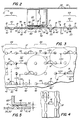
- Air conveyor 10 comprises a deck plate 12, 12'; a plenum chamber 14; and a plurality of article conveying apertures 16, and a plurality of protuberances 18 formed in and extending from deck plate 12.
- Deck plate 12, 12' forms one side of plenum chamber 14.
- Pressurized air within plenum chamber 14 may be directed, as indicated by arrows 20, toward articles 22 (FIGS. 2 and 5) to transport them atop deck plate 12 generally along a transport path in the direction of arrow 24 (FIG. 1 only).
- Pressurized air may be provided to chamber 14 by a blower or the like (not shown in any Figure).
- Plenum chamber 14 may conveniently be constructed from deck plate 12, 12' and a lower wall 26 formed to define the desired chamber area. Appropriately shaped end walls (not shown in any Figure) are preferably also provided to enclose plenum chamber 14.
- Brackets 28 including guide rails 32 are mounted adjacent transport surface 30, 30' on deck plate 12, 12'. Also connected to brackets 28 above guide rails 32 are arms 34 for receiving hold down plate 36. Hold down plate 36 aids in preventing articles 22 from tipping over on deck plate 12, 12'. Preferably, hold down plate 36 is provided with holes 38 permitting air exiting plenum chamber 14 to convey articles 22 in the direction of the conveyor path substantially uniformly across deck plate 12, 12'.
- article conveying apertures 16 are disposed in deck plate 12, 12' in a plurality of conveying rows 40. Most preferably, conveying rows 40 are aligned substantially along the transport path. Apertures 16 are preferably substantially all spaced apart a distance X from each other within each of conveying rows 40.
- protuberances 18 are preferably arranged on deck plate 12, 12' in a plurality of protuberance rows 42. Most preferably, protuberance rows 42 are aligned substantially along the transport path. Protuberances 18, however, are preferably substantially all spaced apart a distance of about one half times X from each other within each of protuberance rows 42.
- At least one, and most preferably two, of protuberance rows 42 are arranged between adjacent ones of conveying aperture rows 40.
- at least one protuberance row 42 is arranged on both sides of every row 40 of conveying apertures 16.
- article conveying apertures 16 in each of conveying rows 40 is disposed in deck plate 12, 12' offset by a distance of about one half times X along the direction of the transport path from conveying apertures 16 in adjacent conveying rows 40.
- adjacent protuberances 18 in adjacent protuberance rows 42 are arranged along lines 44 aligned substantially perpendicular to the transport path.
- conveying aperture rows 40 and protuberance rows 42 are arranged such that apertures 16 also lie along lines 44.
- adjacent protuberance rows 42 are spaced apart a distance of about one half times X.
- protuberances 18 are arranged in a rectangular grid spaced apart at intervals of about one half times X.
- the magnitude of X is selected with reference to the area A (indicated by dashed lines in FIG. 3) of the bottom surface 46 of articles 22.
- Protuberances 18 are preferably spaced apart such that at least three, and most preferably four, protuberances support articles 22 substantially at all times.
- FIGS 1, 2 and 3 permit air conveyors 10, 10' more reliably to function in environments where the conveyor may accumulate material forming a residue which increases sliding resistance between the conveyors 10, 10' and articles 22.
- Prior art air conveyors generally have not reliably functioned in such environments because the increased sliding resistance renders them inefficient and eventually useless.
- Such sliding resistance increasing materials may include particulates or liquids, especially viscous or sticky liquids. Such materials may be carried on or in articles 22, or may be deposited on transport surfaces 30, 30' by other machinery on line with conveyors 10, 10'.
- protuberances 18 extend a distance H from transport surface 30, 30' of deck plate 12, 12' to support bottom surface 46 of articles 22 out of contact with accumulated residue 50 of sliding resistance increasing material 52.
- H will depend upon the amount of material 52 that may accumulate in the particular environment in which conveyor 10, 10' operates.
- protuberances 18 are substantially hemispherical or round and support lower surfaces 46 of articles 22 in substantially point contacts to reduce the area of contact between deck plate 12, 12' and articles 22. Reducing the area of contact between articles 22 and deck plate 12, 12' reduces the area over which slide resistance increasing material 52 may contact articles 22.
- Other shapes are possible for providing the preferred point contacts with bottom surfaces 46 of articles 22.
- other shapes such as oblong protuberances 18' are possible although they do not provide the preferred substantially point contacts with articles 22. Such other shapes, such as oblong protuberances 18', however, may still reduce the area of contact between deck plate 12, 12' and articles 22.
- deck plate 12 includes a plurality of article lifting apertures 54.
- Article lifting apertures 54 direct air, as indicated by arrows 56, outwardly from plenum chamber 14 toward bottom surfaces 46 of articles 22 passing thereover.
- article lifting is meant that apertures aid in lifting articles 22.
- air exits apertures 54 along a direction substantially perpendicularly to both transport surface 30 and the transport path.
- protuberances 18 extending from transport surface 30 of deck plate 12 define a gap 58 between bottom surface 46 of articles 22 and transport surface 30 of air conveyor 10. Air exiting plenum chamber 14 through article lifting apertures 54 substantially fills gap 58 to form an air cushion 60. Air cushion 60 aids in further reducing friction between articles 20 and deck plate 12 or protuberances 18.
- article lifting apertures 54 are preferably disposed in deck plate 12 in a plurality of lifting rows 62. Most preferably, lifting rows 62 are aligned substantially along the transport path. Preferably, article lifting apertures 54 are spaced apart substantially the distance X in each of lifting rows 62.
- lifting rows 62 are disposed between adjacent conveying rows 40; most preferably, lifting rows 62 are disposed between both adjacent conveying rows 40 and protuberance rows 42.
- lifting apertures 54 are also disposed along lines 44 substantially perpendicular to the transport path. Most preferably, lifting apertures 54 are disposed in a rectangular grid.
- conveying rows 40 and protuberance rows 42 are arranged in groups 64 including a conveying row 40 and a protuberance row 42 on each side of conveying row 40.
- a lifting row 62 is preferably disposed between groups 64.
- Air cushion 60 enables air conveyor 10 to convey relatively heavy articles 22 at a relatively low speed.
- relatively heavy articles may generally only be conveyed, if at all by increasing plenum chamber pressure. Increased pressure, however, may cause the articles to be conveyed at excessive speeds and thus to be damaged upon accumulation.
- Air cushion 60 aids in lifting articles 22 making them easier to transport on an air conveyor and at lower speeds.
- protuberances 18 not only prevent the cups from sticking by spilled fluid to deck plate 12, but also enable the relatively heavy metal cups to be conveyed at a relatively low speed through lifting provided by air cushion 60.
- an air conveyor which is relatively efficient and dependable in use.
- an air conveyor of the above character which is used for conveying relatively heavy or other articles tending to stick to the conveyor.
- an air conveyor of the above character which conveys articles at a controlled speed.
- an air conveyor which reduces sliding resistance between the,conveyor and the articles.
- an air conveyor which has a deck plate including a plurality of protuberances.
Landscapes
- Chemical & Material Sciences (AREA)
- Engineering & Computer Science (AREA)
- Fluid Mechanics (AREA)
- Organic Chemistry (AREA)
- Chemical Kinetics & Catalysis (AREA)
- Physics & Mathematics (AREA)
- Combustion & Propulsion (AREA)
- Mechanical Engineering (AREA)
- Drying Of Solid Materials (AREA)
- Manufacturing Of Printed Circuit Boards (AREA)
- Chain Conveyers (AREA)
- Structure Of Belt Conveyors (AREA)
- Intermediate Stations On Conveyors (AREA)
Claims (10)
- Luftförderer zum Fördern von Gegenständen längs einer Transportbahn, welcher aufweist:
eine Sammelkammer (14);
eine Tragplatte (12,12'), welche so angebracht ist, daß sie eine Seite der Sammelkammer bildet;
eine Anzahl von ersten Öffnungen (16) zum Leiten von Luft aus der Sammelkammer gegen die Gegenstände in einer Richtung im wesentlichen längs der Transportbahn, um die Gegenstände zu fördern, eine Anzahl von zweiten Öffnungen (54) zum Leiten von Luft aus der Sammelkammer (14) gegen die Böden der Gegenstände;
gekennzeichnet durch:
eine Anzahl von Vorsprüngen (18), die sich aus der Tragplatte (12,12') erstrecken, zum Aufnehmen jedes Bodens der Gegenstände kontinuierlich an wenigstens drei im wesentlichen punktförmigen Berührungsstellen, um die Berührungsfläche zwischen den Böden der Gegenstände und der Tragplatte (12,12') zu verringern, wobei die zweiten Öffnungen (54) zur Verminderung der Reibung zwischen den Vorsprüngen (18) und den Böden der Gegenstände beitragen. - Luftförderer nach Anspruch 1, bei welchen die ersten Öffnungen (16) in der Tragplatte in einer Anzahl von ersten Reihen (40) im wesentlichen parallel zu der Transportbahn angeordnet sind, die Vorsprünge (18) auf der Tragplatte (12,12') in einer Anzahl von zweiten Reihen (42) im wesentlichen parallel zu der Transportbahn angeordnet sind; und die zweiten Öffnungen (54) in der Tragplatte (12,12') in einer Anzahl von dritten Reihen im wesentlichen parallel zu der Transportbahn angeordnet sind.
- Luftförderer nach Anspruch 2, bei welchem eine der dritten Reihen der zweiten Öffnungen auf der Tragplatte zwischen benachbarten ersten Reihen (40) der ersten Öffnungen angeordnet ist.
- Luftförderer nach Anspruch 2, bei welchem die ersten Öffnungen (16) einen gegenseitigen ersten Abstand X in jeder der ersten Reihen (40) aufweisen und bei welchem die ersten Öffnungen in der Tragplatte an einer Stelle angeordnet sind, die gegenüber den ersten Öffnungen (16) in benachbarten ersten Reihen (40) um einen zweiten Abstand gleich einhalb X längs der Transportbahn versetzt sind.
- Luftförderer nach einem der Ansprüche 2 bis 4, bei welchem Paare der zweiten Reihen (42) der Vorsprünge auf der Tragplatte (12,12') zwischen benachbarten ersten Reihen (40) der ersten Öffnungen angeordnet sind.
- Luftförderer nach einem der Ansprüche 2 bis 5, bei welchem die ersten Öffnungen in jeder der ersten Reihen einen gegenseitigen ersten Abstand X aufweisen und bei welchem die Vorsprünge (18) in jeder der zweiten Reihen (42) einen gegenseitigen zweiten Abstand gleich einhalb X aufweisen.
- Luftförderer nach einem der vorangehenden Ansprüche, bei welchem die Anzahl von zweiten Öffnungen (54) in der Tragplatte zum Leiten von Luft aus der Sammelkammer in den Spalt zwischen den Böden der Gegenstände und der Tragplatte zum Erzeugen eines Luftkissens unterhalb der Gegenstände geeignet ist, um zum Anheben der Gegenstände von der Tragplatte (12,12') beizutragen;
wodurch verhältnismäßig schwere Gegenstände gefördert werden können, ohne daß ein unnötig hoher Luftdruck in die ersten Öffnungen (16) eingeleitet wird, der die Gegenstände veranlassen würde, sich längs der Transportbahn mit verhältnismäßig hohen Geschwindigkeiten zu bewegen, welche die sich ansammelnden Gegenstände beschädigen könnten. - Luftförderer nach einem der vorangehenden Ansprüche, welcher für Umgebungsbedingungen geeignet ist, in denen der Luftförderer Rückstände bildendes Material ansammeln kann, welches den Gleitwiderstand zwischen dem Luftförderer und den Gegenständen erhöht, wobei die Anzahl von Vorsprüngen sich von der Tragplatte (12,12') über einen ausreichenden Abstand erstreckt, um die Böden der Gegenstände im wesentlichen außer Berührung mit den den Gleitwiderstand erhöhenden Rückständen zu halten.
- Luftförderer nach Anspruch 8, bei welchem die Gegenstände das Material mit sich führen, welches den den Gleitwiderstand erhöhenden Rückstand bildet.
- Luftförderer nach Anspruch 8, bei welchem das Material, welches den den Gleitwiderstand erhöhenden Rückstand bildet, eine verhältnismäßig viskose Flüssigkeit ist.
Applications Claiming Priority (2)
| Application Number | Priority Date | Filing Date | Title |
|---|---|---|---|
| US756811 | 1991-09-09 | ||
| US07/756,811 US5129765A (en) | 1991-09-09 | 1991-09-09 | Air conveyor deck having protuberances |
Publications (2)
| Publication Number | Publication Date |
|---|---|
| EP0532151A1 EP0532151A1 (de) | 1993-03-17 |
| EP0532151B1 true EP0532151B1 (de) | 1995-11-22 |
Family
ID=25045153
Family Applications (1)
| Application Number | Title | Priority Date | Filing Date |
|---|---|---|---|
| EP92304479A Expired - Lifetime EP0532151B1 (de) | 1991-09-09 | 1992-05-18 | Luftförderboden mit Protuberanzen |
Country Status (4)
| Country | Link |
|---|---|
| US (1) | US5129765A (de) |
| EP (1) | EP0532151B1 (de) |
| AT (1) | ATE130578T1 (de) |
| DE (1) | DE69206221T2 (de) |
Families Citing this family (6)
| Publication number | Priority date | Publication date | Assignee | Title |
|---|---|---|---|---|
| US5503505A (en) * | 1994-04-13 | 1996-04-02 | Fleetwood Systems, Inc. | Air conveyor with floating covers |
| US6843367B1 (en) * | 2004-02-03 | 2005-01-18 | Dillin Engineered Systems Corp. | Adjustable top guide assembly for air driven conveyor |
| US7481606B2 (en) * | 2006-06-08 | 2009-01-27 | Freddy Robert Lyons | System, method, and apparatus for air-propelled conveyance of workpieces in sanitary environments |
| US7588410B2 (en) * | 2007-10-24 | 2009-09-15 | Fowler Products Company, Llc | Pneumatic conveyor and conveyor section having a curved conveyor path |
| US8490226B2 (en) | 2008-09-19 | 2013-07-23 | Diacor, Inc. | Systems for patient transfer, devices for movement of a patient, and methods for transferring a patient for treatment |
| US10166160B2 (en) * | 2012-02-21 | 2019-01-01 | Qfix Systems, Llc | Air bearing device and method for transferring patients |
Family Cites Families (20)
| Publication number | Priority date | Publication date | Assignee | Title |
|---|---|---|---|---|
| US3273727A (en) * | 1966-09-20 | Load handling apparatus | ||
| US690675A (en) * | 1901-05-09 | 1902-01-07 | Taisey Pneumatic Service Company | Despatch-tube. |
| US3257964A (en) * | 1963-02-20 | 1966-06-28 | Bell Aerospace Corp | Transport means |
| US3473483A (en) * | 1966-10-06 | 1969-10-21 | Ruth S York | Conveyance and track |
| US3513934A (en) * | 1967-04-19 | 1970-05-26 | Boeing Co | Air bearing devices |
| US3413041A (en) * | 1967-05-23 | 1968-11-26 | Gen Motors Corp | In-floor air caster cargo handling system |
| US3545813A (en) * | 1969-04-18 | 1970-12-08 | Tsubakimoto Chain Co | Air-film conveying apparatus |
| JPS51106985A (ja) * | 1971-01-13 | 1976-09-22 | Motsuchi Ando Meriiuezaa Mashi | Eakonbea |
| US3808977A (en) * | 1971-01-18 | 1974-05-07 | Uniflo Systems Co | Switch for vehicle guideway |
| US3692192A (en) * | 1971-06-18 | 1972-09-19 | Borg Warner Canada Ltd | Air cushion lift pad arrangement |
| FR2306146A1 (fr) * | 1975-04-02 | 1976-10-29 | Union Ind Entreprise | Procede et appareillage de fluidification |
| DE2645464C2 (de) * | 1976-10-08 | 1982-05-19 | The Motch & Merryweather Machinery Co., Hayward, Calif. | Einrichtung zum unmittelbaren Fördern von leichten Gegenständen in einer Rinne |
| US4355940A (en) * | 1980-05-21 | 1982-10-26 | Derickson Edward E | Automatic loading platform and method of using same |
| US4392760A (en) * | 1981-03-02 | 1983-07-12 | Futerized Systems, Inc. | Surface flow air conveyor with plenum mounted fan wheel |
| US4437612A (en) * | 1981-12-28 | 1984-03-20 | Midland-Ross Corporation | Flotation nozzle |
| US4621953A (en) * | 1984-12-14 | 1986-11-11 | Foster Wheeler Energy Corporation | Anti-erosion protrusions for wear surfaces in fluid conduits |
| GB8616897D0 (en) * | 1986-07-11 | 1986-08-20 | Systems Ltd | Air cushion device |
| US4805626A (en) * | 1986-11-26 | 1989-02-21 | Fonar Corporation | Air flotation patient bed |
| US4822214A (en) * | 1987-06-12 | 1989-04-18 | Aidlin Automation Corp. | Air conveyor |
| US4828434A (en) * | 1987-08-31 | 1989-05-09 | Goldco Industries, Inc. | Device, apparatus and method for distribution of fluid and selective movement of articles thereby |
-
1991
- 1991-09-09 US US07/756,811 patent/US5129765A/en not_active Expired - Fee Related
-
1992
- 1992-05-18 AT AT92304479T patent/ATE130578T1/de active
- 1992-05-18 DE DE69206221T patent/DE69206221T2/de not_active Expired - Fee Related
- 1992-05-18 EP EP92304479A patent/EP0532151B1/de not_active Expired - Lifetime
Also Published As
| Publication number | Publication date |
|---|---|
| ATE130578T1 (de) | 1995-12-15 |
| DE69206221T2 (de) | 1996-06-20 |
| EP0532151A1 (de) | 1993-03-17 |
| US5129765A (en) | 1992-07-14 |
| DE69206221D1 (de) | 1996-01-04 |
Similar Documents
| Publication | Publication Date | Title |
|---|---|---|
| US3889801A (en) | Vacuum conveyor belt with air bearing | |
| EP0517342B1 (de) | Apparat zum Überführen von Gegenständen wie Eier unter Verwendung einer Bürste | |
| US5029697A (en) | Clean room conveyor | |
| BR0013241A (pt) | Sistema de manipulação automática de bandejas para classificadora | |
| DE69121230D1 (de) | Einrichtung zum Verteilen und Sammeln von zu fördernden Produkten | |
| US5129765A (en) | Air conveyor deck having protuberances | |
| EP1203735B1 (de) | Förderer mit deformierbarem Förderband | |
| DE3264199D1 (en) | Distributing device for a conveyor | |
| US5316131A (en) | Easy maintenance high speed endless belt conveyor | |
| EP0521541B1 (de) | Rutsche mit Bremsmittel | |
| CA1304037C (en) | Adjustable width chain conveyor | |
| GR3031110T3 (en) | Device for conveying layered material. | |
| US3545813A (en) | Air-film conveying apparatus | |
| GB2093422A (en) | Vertical conveyor | |
| US5107981A (en) | Device with flow medium stratification for positioning and/or transporting unit loads | |
| US3478864A (en) | Apparatus for supporting strip material on a gas cushion | |
| CA1088965A (en) | Conveyor system | |
| EP0392621A1 (de) | Förderer | |
| GB2162143A (en) | A belt conveyor supported on an air cushion | |
| US4763774A (en) | Transport device | |
| US3863754A (en) | Flat wire conveyor belt with improved covering | |
| US5295574A (en) | Infeed boot and method of loading articles for a vacuum conveyor | |
| GB2235674A (en) | Conveyor system | |
| EP1025029B1 (de) | Sortiereinrichtung für rückgabedruckerzeugnisse | |
| GB2320004A (en) | Air conveyor |
Legal Events
| Date | Code | Title | Description |
|---|---|---|---|
| PUAI | Public reference made under article 153(3) epc to a published international application that has entered the european phase |
Free format text: ORIGINAL CODE: 0009012 |
|
| AK | Designated contracting states |
Kind code of ref document: A1 Designated state(s): AT BE CH DE DK ES FR GB GR IT LI LU MC NL PT SE |
|
| 17P | Request for examination filed |
Effective date: 19930422 |
|
| 17Q | First examination report despatched |
Effective date: 19941004 |
|
| GRAA | (expected) grant |
Free format text: ORIGINAL CODE: 0009210 |
|
| AK | Designated contracting states |
Kind code of ref document: B1 Designated state(s): AT BE CH DE DK ES FR GB GR IT LI LU MC NL PT SE |
|
| PG25 | Lapsed in a contracting state [announced via postgrant information from national office to epo] |
Ref country code: NL Free format text: LAPSE BECAUSE OF FAILURE TO SUBMIT A TRANSLATION OF THE DESCRIPTION OR TO PAY THE FEE WITHIN THE PRESCRIBED TIME-LIMIT Effective date: 19951122 Ref country code: LI Effective date: 19951122 Ref country code: GR Free format text: LAPSE BECAUSE OF FAILURE TO SUBMIT A TRANSLATION OF THE DESCRIPTION OR TO PAY THE FEE WITHIN THE PRESCRIBED TIME-LIMIT Effective date: 19951122 Ref country code: ES Free format text: THE PATENT HAS BEEN ANNULLED BY A DECISION OF A NATIONAL AUTHORITY Effective date: 19951122 Ref country code: DK Effective date: 19951122 Ref country code: CH Effective date: 19951122 Ref country code: AT Effective date: 19951122 |
|
| REF | Corresponds to: |
Ref document number: 130578 Country of ref document: AT Date of ref document: 19951215 Kind code of ref document: T |
|
| REF | Corresponds to: |
Ref document number: 69206221 Country of ref document: DE Date of ref document: 19960104 |
|
| ET | Fr: translation filed | ||
| ITF | It: translation for a ep patent filed | ||
| PG25 | Lapsed in a contracting state [announced via postgrant information from national office to epo] |
Ref country code: SE Effective date: 19960222 Ref country code: PT Effective date: 19960222 |
|
| NLV1 | Nl: lapsed or annulled due to failure to fulfill the requirements of art. 29p and 29m of the patents act | ||
| PG25 | Lapsed in a contracting state [announced via postgrant information from national office to epo] |
Ref country code: MC Effective date: 19960531 Ref country code: LU Free format text: LAPSE BECAUSE OF NON-PAYMENT OF DUE FEES Effective date: 19960531 |
|
| REG | Reference to a national code |
Ref country code: CH Ref legal event code: PL |
|
| PLBE | No opposition filed within time limit |
Free format text: ORIGINAL CODE: 0009261 |
|
| STAA | Information on the status of an ep patent application or granted ep patent |
Free format text: STATUS: NO OPPOSITION FILED WITHIN TIME LIMIT |
|
| 26N | No opposition filed | ||
| PGFP | Annual fee paid to national office [announced via postgrant information from national office to epo] |
Ref country code: GB Payment date: 19990512 Year of fee payment: 8 |
|
| PGFP | Annual fee paid to national office [announced via postgrant information from national office to epo] |
Ref country code: BE Payment date: 19990517 Year of fee payment: 8 |
|
| PGFP | Annual fee paid to national office [announced via postgrant information from national office to epo] |
Ref country code: FR Payment date: 19990518 Year of fee payment: 8 |
|
| PGFP | Annual fee paid to national office [announced via postgrant information from national office to epo] |
Ref country code: DE Payment date: 19990624 Year of fee payment: 8 |
|
| PG25 | Lapsed in a contracting state [announced via postgrant information from national office to epo] |
Ref country code: GB Free format text: LAPSE BECAUSE OF NON-PAYMENT OF DUE FEES Effective date: 20000518 |
|
| PG25 | Lapsed in a contracting state [announced via postgrant information from national office to epo] |
Ref country code: BE Free format text: LAPSE BECAUSE OF NON-PAYMENT OF DUE FEES Effective date: 20000531 |
|
| BERE | Be: lapsed |
Owner name: SIMPLIMATIC ENGINEERING CY Effective date: 20000531 |
|
| GBPC | Gb: european patent ceased through non-payment of renewal fee |
Effective date: 20000518 |
|
| PG25 | Lapsed in a contracting state [announced via postgrant information from national office to epo] |
Ref country code: FR Free format text: LAPSE BECAUSE OF NON-PAYMENT OF DUE FEES Effective date: 20010131 |
|
| PG25 | Lapsed in a contracting state [announced via postgrant information from national office to epo] |
Ref country code: DE Free format text: LAPSE BECAUSE OF NON-PAYMENT OF DUE FEES Effective date: 20010301 |
|
| REG | Reference to a national code |
Ref country code: FR Ref legal event code: ST |
|
| PG25 | Lapsed in a contracting state [announced via postgrant information from national office to epo] |
Ref country code: IT Free format text: LAPSE BECAUSE OF NON-PAYMENT OF DUE FEES;WARNING: LAPSES OF ITALIAN PATENTS WITH EFFECTIVE DATE BEFORE 2007 MAY HAVE OCCURRED AT ANY TIME BEFORE 2007. THE CORRECT EFFECTIVE DATE MAY BE DIFFERENT FROM THE ONE RECORDED. Effective date: 20050518 |