EP0532165A2 - Druckluftabdichtung für Verbrennungskammer - Google Patents
Druckluftabdichtung für Verbrennungskammer Download PDFInfo
- Publication number
- EP0532165A2 EP0532165A2 EP92306564A EP92306564A EP0532165A2 EP 0532165 A2 EP0532165 A2 EP 0532165A2 EP 92306564 A EP92306564 A EP 92306564A EP 92306564 A EP92306564 A EP 92306564A EP 0532165 A2 EP0532165 A2 EP 0532165A2
- Authority
- EP
- European Patent Office
- Prior art keywords
- combustion chamber
- buffer space
- mixer
- burner assembly
- blower
- Prior art date
- Legal status (The legal status is an assumption and is not a legal conclusion. Google has not performed a legal analysis and makes no representation as to the accuracy of the status listed.)
- Granted
Links
- 238000002485 combustion reaction Methods 0.000 title claims abstract description 78
- 230000035515 penetration Effects 0.000 claims abstract description 19
- 238000011144 upstream manufacturing Methods 0.000 claims description 2
- 239000007789 gas Substances 0.000 description 13
- 239000002184 metal Substances 0.000 description 12
- 230000000284 resting effect Effects 0.000 description 6
- 239000007788 liquid Substances 0.000 description 5
- 239000000567 combustion gas Substances 0.000 description 3
- 239000000203 mixture Substances 0.000 description 2
- 229910010271 silicon carbide Inorganic materials 0.000 description 2
- 238000004140 cleaning Methods 0.000 description 1
- 230000001627 detrimental effect Effects 0.000 description 1
- 238000007689 inspection Methods 0.000 description 1
- 238000012423 maintenance Methods 0.000 description 1
- 238000012986 modification Methods 0.000 description 1
- 230000004048 modification Effects 0.000 description 1
- 238000007789 sealing Methods 0.000 description 1
- 125000006850 spacer group Chemical group 0.000 description 1
Images



Classifications
-
- F—MECHANICAL ENGINEERING; LIGHTING; HEATING; WEAPONS; BLASTING
- F24—HEATING; RANGES; VENTILATING
- F24H—FLUID HEATERS, e.g. WATER OR AIR HEATERS, HAVING HEAT-GENERATING MEANS, e.g. HEAT PUMPS, IN GENERAL
- F24H1/00—Water heaters, e.g. boilers, continuous-flow heaters or water-storage heaters
- F24H1/22—Water heaters other than continuous-flow or water-storage heaters, e.g. water heaters for central heating
- F24H1/40—Water heaters other than continuous-flow or water-storage heaters, e.g. water heaters for central heating with water tube or tubes
- F24H1/43—Water heaters other than continuous-flow or water-storage heaters, e.g. water heaters for central heating with water tube or tubes helically or spirally coiled
-
- F—MECHANICAL ENGINEERING; LIGHTING; HEATING; WEAPONS; BLASTING
- F23—COMBUSTION APPARATUS; COMBUSTION PROCESSES
- F23D—BURNERS
- F23D14/00—Burners for combustion of a gas, e.g. of a gas stored under pressure as a liquid
- F23D14/34—Burners specially adapted for use with means for pressurising the gaseous fuel or the combustion air
- F23D14/36—Burners specially adapted for use with means for pressurising the gaseous fuel or the combustion air in which the compressor and burner form a single unit
-
- F—MECHANICAL ENGINEERING; LIGHTING; HEATING; WEAPONS; BLASTING
- F23—COMBUSTION APPARATUS; COMBUSTION PROCESSES
- F23M—CASINGS, LININGS, WALLS OR DOORS SPECIALLY ADAPTED FOR COMBUSTION CHAMBERS, e.g. FIREBRIDGES; DEVICES FOR DEFLECTING AIR, FLAMES OR COMBUSTION PRODUCTS IN COMBUSTION CHAMBERS; SAFETY ARRANGEMENTS SPECIALLY ADAPTED FOR COMBUSTION APPARATUS; DETAILS OF COMBUSTION CHAMBERS, NOT OTHERWISE PROVIDED FOR
- F23M11/00—Safety arrangements
- F23M11/02—Preventing emission of flames or hot gases, or admission of air, through working or charging apertures
Definitions
- the invention relates to combustion apparatus, and more particularly to a sealing arrangement preventing leakage of combustion products through penetrations and interfaces, such as piping and mixer and burner penetrations and end wall interfaces, without requiring leak-tight seals.
- the pressure of gases within the combustion chamber is usually greater than that of the surroundings. It is often difficult to assure that penetrations for components that pass through the wall of the combustion chamber will not leak, especially since such components must often be readily removable for service or replacement. Also, it is usually necessary for a wall or panel of the combustion chamber to be removable for inspection or maintenance of the combustion chamber or heat exchanger within it. While it is possible to provide individual leak-tight seals for such components, it is expensive to do so, and furthermore it cannot be assured that they will be maintained in proper condition.
- the present invention provides penetration and interface seals that are permitted to leak slightly.
- the invention conditions the environment of the seals so that the leakage is not detrimental.
- the invention provides an air seal arrangement and combination including a buffer space at penetrations and interfaces, and pressurizes the buffer space to a higher pressure than the combustion chamber, such that any leakage flows into the combustion chamber rather out of the combustion chamber.
- the direction of leakage into the combustion chamber prevents unwanted escape of combustion gases. Any leakage from the buffer space to the atmosphere will simply be air leakage.
- the arrangement prevents leakage of gases from the combustion chamber without relying upon leak-tight fittings or seals.
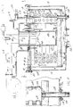
- FIG. 1 is a schematic illustration of combustion apparatus in accordance with the invention.
- FIG. 2 is a side view partially in section of combustion apparatus in accordance with the invention.
- FIG. 3 is an enlarged view of a portion of the structure of FIG. 2.
- FIG. 4 is a sectional view taken along line 4-4 of FIG. 2.
- FIG. 5 is a sectional view taken along line 5-5 of FIG. 4.
- FIG. 6 is a view like FIG. 2 and shows an alternate embodiment.
- FIG. 7 is an enlarged view of a portion of the structure of FIG. 6.
- FIG. 8 is a sectional view taken along line 8-8 of FIG. 6.
- FIG. 1 shows combustion apparatus 10 including a combustion chamber 12 having distally opposite top and bottom end walls 14 and 16, and having a sidewall 18 extending between the end walls.
- the combustion chamber has an upper opening 20 covered and closed by end wall 14, and has a lower exhaust outlet 22 through end wall 16.
- a cover 24 external to the combustion chamber covers end wall 14 and defines a buffer space 26 therebetween.
- One or more penetrations, including a mixer and burner assembly 28, extends through cover 24 and end wall 14 into the combustion chamber.
- Buffer space 26 has a buffer outlet at penetration 30.
- Blower 32 supplies air along path 34 through pressure dropping orifice 36 to mixer and burner assembly 28.
- a gas valve 38 supplies combustion gas to the air stream at gas inlet port 40 downstream of pressure dropping orifice 36.
- the combustible air-gas mixture flows downwardly in mixer and burner assembly 28 and then radially outwardly through orifices 42 and is ignited to provide heat to a heat exchanger, FIGS. 2 and 6, in combustion chamber 12 to in turn heat liquid in the heat exchanger.
- Blower 32 supplies air along path 44 to buffer space 26.
- Pressure dropping orifices 36 and 42 provide a restricted flow path of smaller diameter than flow path 44, such that buffer space 26 is pressurized to a higher pressure than the combustion chamber, such that leakage at penetration 46 flows from buffer space 26 into combustion chamber 12, rather than the reverse.
- the sum of the pressure drops across orifices 36 and 42 relative to the pressure drop across exhaust outlet 22 is greater than the pressure drop from blower 32 along path 44 to buffer space 26 relative to buffer outlet 30, i.e., where R1 is the pressure drop from the blower to the mixer and burner assembly across pressure dropping orifice 36, R2 is the pressure drop from the mixer and burner assembly across orifices 42 to the combustion chamber, R3 is the pressure drop from the blower to the buffer space, R4 is the pressure drop across buffer outlet 30, and R5 is the pressure drop across exhaust outlet 22.
- combustion chamber 12 has distally opposite top and bottom end walls 14 and 16, and a sidewall 18 extending between the end walls.
- Cover 24 is external to combustion chamber 12 and covers end wall 14 and defines buffer space 26 therebetween.
- End wall 14 has penetrations therethrough, including forced draft mixer and burner assembly 28, flame sensor 50, ignitor 52, and header pipes 54 and 56, FIG. 4.
- Blower 32 is external to cover 24 and supplies air to buffer space 26 and pressurizes the buffer space to a higher pressure than combustion chamber 12 such that leakage at the penetrations flows from the buffer space into the combustion chamber.
- Conduit 58 supplies air along path 34 from blower 32 through pressure dropping orifice 36 to mixer and burner assembly 28.
- Conduit 60 independently supplies air along path 44 from blower 32 to buffer space 26 and pressurizes the buffer space to a higher pressure than the interior of combustion chamber 12.
- the combustion products flow radially outwardly and then downwardly as shown at arrows 65, and are exhausted as shown at arrows 66 at outlet 22.
- the combined pressure drops provided across pressure dropping orifice 36 and orifices 42 relative to exhaust outlet 22 is greater than the pressure drop through conduit 60 to buffer space 26 relative to the buffer outlets at the penetrations, such that the pressure in the combustion chamber is less than the pressure in buffer space 26, and hence leakage at penetrations through end wall 14 flows from buffer space 26 into combustion chamber 12, rather than the reverse.
- End wall 14 is provided by three layers, including metal plate 68, FIG. 3, a heat insulating blanket 70, such as provided by Carborundum Corporation under the tradename Fiberfrax Durablanket, and a lower heat insulating board 72, such as provided by Carborundum Corporation under the tradename Fiberfrax Duraboard.
- a heat insulating blanket 70 such as provided by Carborundum Corporation under the tradename Fiberfrax Durablanket
- a lower heat insulating board 72 such as provided by Carborundum Corporation under the tradename Fiberfrax Duraboard.
- tray 84 is mounted on plate 68 by respective nuts such as 78 and 80 and extend downwardly and at their bottom ends curl around a short length of a respective dowel rod such as 80, 82 which is welded to the underside of a metal tray 84, such that tray 84 is suspended and supported below metal plate 68 and adjusted by threaded nuts 78 and 80 at the upper end of respective J-bolts 74 and 76.
- a heat insulating blanket 86 such as provided by the above noted Fiberfrax Durablanket
- a heat insulating board 88 such as provided by the above noted Fiberfrax Duraboard.
- Heat exchanger coil 64 is disposed between boards 88 and 72.
- a heat insulating blanket 92 such as provided by the above noted Fiberfrax Durablanket
- a heat insulating board 94 such as provided by the above noted Fiberfrax Duraboard.
- Board 94 engages the bottom 96 of lower portion 98 of the mixer and burner assembly 28.
- Lower portion 98 of the mixer and burner assembly has an upper flange 100, FIG. 3, resting on gasket 102 on metal plate 68.
- Upper portion 104 of the mixer and burner assembly has a lower flange 106 resting on gasket 108 on flange 110 of cover 24.
- the outer edge of metal plate 68 rests on support blocks 112 welded to the inside of sidewall 18 of combustion chamber 12.
- Plate 68 is secured to support blocks 112 at bolts 114.
- Clamp blocks 116 are welded to the outside of sidewall 18 of the combustion chamber and have bolts 118 extending upwardly therefrom for receiving clamps 120 which clamp cover 24 downwardly on the combustion chamber at upper opening 20 at gasket 122.
- Header pipe 56 The liquid to be heated enters through header pipe 56, FIG. 4, circulates through heat exchanger coil 64, and exits through header pipe 54.
- Header pipe 56 has a lower manifold section 124, FIG. 5, with removable plugs 126 for accessing and cleaning respective sections of heat exchanger coil 64, and has a lower drain 128 which extends downwardly through bottom end wall 16 and is preferably leak-tight sealed thereto by gaskets 130, 132, plate 134, and bolts 136.
- Header pipe 154 includes lower portion 138, FIG. 3, extending downwardly through cover 24, spacer 140, plate 68, and sleeve 142 through layers 70 and 72.
- Header pipe 54 includes an upper portion 144 mounted by bolts 146 and flange 148 to upper flange 150 of lower portion 138 and providing a seal at O-ring 152.
- the upper portion of header pipe 56 is comparable.
- Upper portion 144 of header pipe 54 includes first and second temperature sensors 154 and 156.
- air from air inlet 200 is supplied by blower 202 as shown at arrows 204 to buffer space 206 between cover 208 and end wall 210 of combustion chamber 212.
- the combustion chamber has distally opposite top and bottom end walls 210 and 214, and a sidewall 216 extending between the end walls.
- the combustion chamber has an upper opening 218 covered and closed by top end wall 210, and has a lower exhaust outlet 220 through bottom end wall 214.
- Mixer and burner assembly 222 has a lower portion 224 extending downwardly through top end wall 210 and into combustion chamber 212.
- Mixer and burner assembly 222 has an upper portion 226 external of the combustion chamber.
- a second cover 228 is external to first cover 208 and covers external portion 226 of mixer and burner assembly 222 and defines a second buffer space 230 therebetween.
- Mixer and burner assembly 222 at upper portion 226 has inlet ports 232 communicating with buffer space 230.
- Cover 208 has a port 234 communicating with buffer space 230 such that buffer spaces 206 and 230 are in communication with each other through port 234.
- Air from blower 202 supplied to buffer space 206 also flows through port 234 as shown at arrows 236 to buffer space 230 and then to inlet 232 and into the mixer and burner assembly as shown at arrows 238.
- Combustion gas is supplied at gas inlet port 240 from gas valve 242.
- the combustion air and gas flows downwardly in mixer and burner assembly 222 as shown at arrow 243 and then radially outwardly as shown at arrows 244 through orifices 246 in sidewall 248 of lower portion 224 of the mixer and burner assembly, and into the interior of combustion chamber 212 for ignition by ignitor 250, to in turn heat the liquid in heat exchanger coil 252.
- Pressure dropping orifices 232 and 246 provide a restricted flow path reducing the pressure in the combustion chamber to a pressure lower than that in buffer space 206, such that the buffer space is pressurized to a higher pressure than the combustion chamber, and leakage at penetrations flows from buffer space 206 into combustion chamber 212, rather than the reverse.
- the sum of the pressure drops across orifices 232 and 246 relative to that across exhaust outlet 220 is greater than the pressure drop from blower 202 into space 206 across inlet 256 relative to the buffer outlets at the penetrations.
- Top end wall 210 is provided by three layers including an upper metal plate 258, a central heat insulating blanket 260, such as provided by the above noted Fiberfrax Durablanket, and a lower heat insulating board 262, such as provided by the above noted Fiberfrax Duraboard.
- the outer edge of metal plate 258 rests on an annular disc 264 which is welded to sidewall 216 of the combustion chamber at upper opening 218.
- the outer edge of annular disc 264 rests on supporting side rails 266 and 268 which are part of the mounting structure for the combustion chamber.
- Another side rail (not shown) is provided behind the combustion chamber, and the combustion chamber is slid into the page in FIG. 6 between side rail supports 266 and 268 to be supported thereby and by the rear side rail support.
- J-bolts Extending downwardly from metal plate 258 are four elongated J-bolts, two of which are shown at 270 and 272.
- the lower end of the J-bolts curl around a short length of dowel rod such as 274, 276 which is welded to the underside of a metal tray 278, such that tray 278 is suspended and supported below metal plate 258 and adjusted by threaded nuts 280 and 282 at the upper end of respective J-bolts 270 and 272.
- a heat insulating blanket 284 such as provided by the above noted Fiberfrax Durablanket
- a heat insulating board 286, such as provided by the above noted Fiberfrax Duraboard.
- Heat exchanger coil 252 is disposed between boards 286 and 262.
- Board 290 engages the bottom 292 of lower portion 224 of mixer and burner assembly 222.
- Mixer and burner assembly 222 includes the noted lower and upper portions 224 and 226 bolted to each other at flanges 294 and 296 and welded to metal plate 258 at weldment 298, FIG. 7.
- Cover 208 is mounted to end wall 210 by bolts such as 300, 302, 304, FIG. 7, which are welded to plate 258 at respective weldments 306, 308, 310 and extend upwardly through cover 208 and metal plate 312 and are secured by respective nuts 314, 316, 318.
- the outer circumferential edge of cover 208 is received in gasket 320 on annular disc 264.
- Cover 228 rests on plate 312 on cover 208 and is welded thereto at weldment 322.
- Header pipe 324 includes a lower portion 326 extending through layers 258, 260, 262 of wall 210, and an upper portion 328 extending through cover 208 at grommet 330. Header pipe 332 is comparable.
- the liquid to be heated flows through inlet header pipe 324 as pumped by pump 334, and flows through heat exchanger coil 252, and exits through header pipe 332.
- a first conduit 58 supplies air from the blower to the mixer and burner assembly
- a second conduit 60 independently supplies air from the blower to the buffer space. Air flows through first conduit 58 along a path 34 from blower 32 to mixer and burner assembly 28 without passing through buffer space 26.
- air from blower 202 flows through buffer space 206 to mixer and burner assembly 222.
- the penetrations such as the mixer and burner assembly, header pipes, ignitors, flame sensors, etc., extend through the combustion chamber end wall 14, 210 and the cover 24, 208 in non-leak-tight relation, eliminating the need for leak-tight seals therebetween.
- the interface 334, FIG. 2, and 336, FIG. 6, along which the combustion chamber opening 20, 218 is covered by the top end wall 14, 210, is also within the buffer space 26, 206 and covered by the cover 24, 208, such that leakage at the interface 334, 336 flows from the buffer space 26, 206 into the combustion chamber 12, 212, eliminating the need for a leak-tight seal at such interface 334, 336.
- gasket 338 at interface 334 may be eliminated.
- the cover 24, 208 covers only the top end wall 14, 210 of the combustion chamber 12, 212, and not the other end wall 16, 214 nor the sidewall 18, 216, such that the latter are accessible without removing the cover 24, 208.
- the buffer space 26, 206 is thin and flat and covers only the top end wall of the combustion chamber.
- pressure dropping orifice 36 is between blower 32 and mixer and burner assembly 28.
- Gas inlet port 40 is external to cover 24 and downstream of pressure dropping orifice 36.
- Buffer space 26 communicates with blower 32 through path 42 upstream of pressure dropping orifice 36.
Landscapes
- Engineering & Computer Science (AREA)
- Chemical & Material Sciences (AREA)
- Combustion & Propulsion (AREA)
- Mechanical Engineering (AREA)
- General Engineering & Computer Science (AREA)
- Physics & Mathematics (AREA)
- Thermal Sciences (AREA)
- Gas Burners (AREA)
- Instantaneous Water Boilers, Portable Hot-Water Supply Apparatuses, And Control Of Portable Hot-Water Supply Apparatuses (AREA)
Applications Claiming Priority (2)
| Application Number | Priority Date | Filing Date | Title |
|---|---|---|---|
| US756503 | 1991-09-09 | ||
| US07/756,503 US5171144A (en) | 1991-09-09 | 1991-09-09 | Pressurized air seal for combustion chamber |
Publications (3)
| Publication Number | Publication Date |
|---|---|
| EP0532165A2 true EP0532165A2 (de) | 1993-03-17 |
| EP0532165A3 EP0532165A3 (en) | 1993-07-14 |
| EP0532165B1 EP0532165B1 (de) | 1995-10-18 |
Family
ID=25043777
Family Applications (1)
| Application Number | Title | Priority Date | Filing Date |
|---|---|---|---|
| EP92306564A Expired - Lifetime EP0532165B1 (de) | 1991-09-09 | 1992-07-17 | Druckluftabdichtung für Verbrennungskammer |
Country Status (4)
| Country | Link |
|---|---|
| US (2) | US5171144A (de) |
| EP (1) | EP0532165B1 (de) |
| CA (1) | CA2074976C (de) |
| DE (1) | DE69205536T2 (de) |
Families Citing this family (11)
| Publication number | Priority date | Publication date | Assignee | Title |
|---|---|---|---|---|
| JPH0798122B2 (ja) * | 1991-07-12 | 1995-10-25 | 動力炉・核燃料開発事業団 | 核燃料サイクルから発生する使用済溶媒の再生方法 |
| AT402667B (de) * | 1995-03-20 | 1997-07-25 | Vaillant Gmbh | Wasserheizer wasserheizer |
| US5516278A (en) * | 1995-03-08 | 1996-05-14 | Aos Holding Company | Forced draft mixer and burner assembly with pressure distribution device |
| FR2732753B1 (fr) * | 1995-04-07 | 1998-05-22 | Morice & Cie Traitogaz | Dispositif d'injection d'air pour bruleur a air souffle |
| US5575640A (en) * | 1995-06-07 | 1996-11-19 | Frontier, Inc. | Burner for gas burning apparatus |
| US7032543B1 (en) * | 2005-01-12 | 2006-04-25 | Aos Holding Company | Water heater with pressurized combustion |
| ITRM20050606A1 (it) * | 2005-12-05 | 2007-06-06 | Mf S R L | Scambiatore perfezionato. |
| CN101571315B (zh) * | 2009-06-16 | 2012-05-16 | 艾欧史密斯(中国)热水器有限公司 | 一种容积式燃气热水器 |
| US9631808B2 (en) * | 2014-11-21 | 2017-04-25 | Honeywell International Inc. | Fuel-air-flue gas burner |
| IT201700096656A1 (it) * | 2017-08-28 | 2019-02-28 | Cosmogas Srl | Scambiatore di calore per una caldaia, e tubo di scambiatore di calore |
| WO2020244763A1 (de) * | 2019-06-06 | 2020-12-10 | Alfred Kärcher SE & Co. KG | Gasbrenner und durchlauferhitzer eines hochdruckreinigungsgeräts mit einem gasbrenner |
Family Cites Families (15)
| Publication number | Priority date | Publication date | Assignee | Title |
|---|---|---|---|---|
| US2599153A (en) * | 1948-05-01 | 1952-06-03 | Reginald W Beckett | Oil burner of the atomizing type |
| US2844271A (en) * | 1955-03-14 | 1958-07-22 | Continental Oil Co | Pressure tank |
| US3226467A (en) * | 1960-09-28 | 1965-12-28 | Heraeus Gmbh W C | Double-walled ultra-high vacuum vessel defining a work chamber |
| US3752224A (en) * | 1971-09-21 | 1973-08-14 | Chicago Bridge & Iron Co | Jacket cooled header air distribution system for fluidized bed reactor |
| US3838666A (en) * | 1972-12-27 | 1974-10-01 | Stone Platt Crawley Ltd | Fluid heaters |
| US3822987A (en) * | 1973-01-29 | 1974-07-09 | Morse Boulger Inc | Thermal sterilizer for contaminated air |
| US3942324A (en) * | 1974-07-12 | 1976-03-09 | Forenade Fabriksverken | Hot gas engine |
| US4252520A (en) * | 1978-08-21 | 1981-02-24 | Slyman Manufacturing Corporation | Infra-red domestic furnace |
| US4280474A (en) * | 1979-10-09 | 1981-07-28 | Ruegg Sr Harvey L | Heat hugger |
| US4366778A (en) * | 1980-03-27 | 1983-01-04 | Paquet Thermique, S.A. | Gas boiler able to operate in a sealed combustion circuit |
| FR2549938B1 (fr) * | 1983-07-25 | 1987-08-07 | Fonderie Soc Gen De | Bruleur a premelange gazeux et chaudiere equipee d'un tel bruleur |
| NL8304041A (nl) * | 1983-11-24 | 1985-06-17 | Remeha Fabrieken Bv | Verwarmingsketel met verticale branderbuis. |
| FR2567624B1 (fr) * | 1984-07-10 | 1986-11-28 | Francais Ciments | Generateur d'air chaud a temperature elevee pour installation de sechage par exemple de briquetterie, de cimenteries ou de produits agricoles, de chauffage de locaux |
| US4723513A (en) * | 1986-01-30 | 1988-02-09 | Lochinvar Water Heater Corporation | Gas water heater/boiler |
| IT1241559B (it) * | 1990-12-21 | 1994-01-17 | Merloni Termosanitari Spa | Caldaia murale a gas con bruciatore a premiscelazione, in particolare per uso domestico. |
-
1991
- 1991-09-09 US US07/756,503 patent/US5171144A/en not_active Ceased
-
1992
- 1992-07-17 DE DE69205536T patent/DE69205536T2/de not_active Expired - Fee Related
- 1992-07-17 EP EP92306564A patent/EP0532165B1/de not_active Expired - Lifetime
- 1992-07-30 CA CA002074976A patent/CA2074976C/en not_active Expired - Fee Related
-
1996
- 1996-05-02 US US08/641,867 patent/USRE37383E1/en not_active Expired - Lifetime
Also Published As
| Publication number | Publication date |
|---|---|
| CA2074976A1 (en) | 1993-03-10 |
| EP0532165A3 (en) | 1993-07-14 |
| CA2074976C (en) | 1996-10-22 |
| US5171144A (en) | 1992-12-15 |
| DE69205536T2 (de) | 1996-04-25 |
| DE69205536D1 (de) | 1995-11-23 |
| EP0532165B1 (de) | 1995-10-18 |
| USRE37383E1 (en) | 2001-09-18 |
Similar Documents
| Publication | Publication Date | Title |
|---|---|---|
| US5171144A (en) | Pressurized air seal for combustion chamber | |
| US8292616B2 (en) | Burner | |
| US5517822A (en) | Mobile congeneration apparatus including inventive valve and boiler | |
| US6106276A (en) | Gas burner system providing reduced noise levels | |
| US3935705A (en) | Exhaust manifold for an internal combustion engine | |
| US7137378B1 (en) | Component mounting system for a marine engine | |
| CA2037863C (en) | Apparatus for burning oxidizable components in an exhaust flow | |
| CA2266975C (en) | Alternative vertical or horizontal vent for a gas combustion apparatus | |
| HU9502521D0 (en) | Device and process for burning oxidisable components in a vehicle gas to be purified | |
| US20170211845A1 (en) | Device for dispensing a heated fluid | |
| CA1251698A (en) | High-efficiency thermal group | |
| FR2755752B1 (fr) | Module hydraulique pour installation de chauffage central et de production d'eau chaude, et chaudiere equipee d'un tel module | |
| CA1158494A (en) | Water heater | |
| DE2227392C2 (de) | Durchlauferhitzer | |
| US4176709A (en) | Stack-type heat exchanger | |
| GB1344810A (en) | Burner for gas-fired apparatus | |
| TW368550B (en) | Device for conducting an exhaust gas mass flow and/or for receiving a catalytic converter supporting body | |
| SU1040901A1 (ru) | Стенд дл испытани камер сгорани | |
| US4456171A (en) | Vehicle heater | |
| EP0655579A1 (de) | Brenner | |
| EP0052055A1 (de) | Heizkessel mit abgeschlossener Brennkammer und zylindrischem Wärmetauscher | |
| JP7592071B2 (ja) | 排気に空気を噴射するための装置 | |
| JPH046813Y2 (de) | ||
| RU54656U1 (ru) | Горелка для сжигания газообразного и жидкого топлива | |
| JP2951017B2 (ja) | 燃焼機の排気装置 |
Legal Events
| Date | Code | Title | Description |
|---|---|---|---|
| PUAI | Public reference made under article 153(3) epc to a published international application that has entered the european phase |
Free format text: ORIGINAL CODE: 0009012 |
|
| AK | Designated contracting states |
Kind code of ref document: A2 Designated state(s): DE FR GB IT NL |
|
| PUAL | Search report despatched |
Free format text: ORIGINAL CODE: 0009013 |
|
| AK | Designated contracting states |
Kind code of ref document: A3 Designated state(s): DE FR GB IT NL |
|
| 17P | Request for examination filed |
Effective date: 19930906 |
|
| 17Q | First examination report despatched |
Effective date: 19940531 |
|
| GRAA | (expected) grant |
Free format text: ORIGINAL CODE: 0009210 |
|
| AK | Designated contracting states |
Kind code of ref document: B1 Designated state(s): DE FR GB IT NL |
|
| ITF | It: translation for a ep patent filed | ||
| REF | Corresponds to: |
Ref document number: 69205536 Country of ref document: DE Date of ref document: 19951123 |
|
| ET | Fr: translation filed | ||
| PLBE | No opposition filed within time limit |
Free format text: ORIGINAL CODE: 0009261 |
|
| STAA | Information on the status of an ep patent application or granted ep patent |
Free format text: STATUS: NO OPPOSITION FILED WITHIN TIME LIMIT |
|
| 26N | No opposition filed | ||
| PGFP | Annual fee paid to national office [announced via postgrant information from national office to epo] |
Ref country code: FR Payment date: 20010611 Year of fee payment: 10 |
|
| REG | Reference to a national code |
Ref country code: GB Ref legal event code: IF02 |
|
| PGFP | Annual fee paid to national office [announced via postgrant information from national office to epo] |
Ref country code: DE Payment date: 20020619 Year of fee payment: 11 |
|
| PG25 | Lapsed in a contracting state [announced via postgrant information from national office to epo] |
Ref country code: FR Free format text: LAPSE BECAUSE OF NON-PAYMENT OF DUE FEES Effective date: 20030331 |
|
| REG | Reference to a national code |
Ref country code: FR Ref legal event code: ST |
|
| PG25 | Lapsed in a contracting state [announced via postgrant information from national office to epo] |
Ref country code: DE Free format text: LAPSE BECAUSE OF NON-PAYMENT OF DUE FEES Effective date: 20040203 |
|
| PG25 | Lapsed in a contracting state [announced via postgrant information from national office to epo] |
Ref country code: IT Free format text: LAPSE BECAUSE OF NON-PAYMENT OF DUE FEES;WARNING: LAPSES OF ITALIAN PATENTS WITH EFFECTIVE DATE BEFORE 2007 MAY HAVE OCCURRED AT ANY TIME BEFORE 2007. THE CORRECT EFFECTIVE DATE MAY BE DIFFERENT FROM THE ONE RECORDED. Effective date: 20050717 |
|
| PGFP | Annual fee paid to national office [announced via postgrant information from national office to epo] |
Ref country code: GB Payment date: 20070727 Year of fee payment: 16 |
|
| PGFP | Annual fee paid to national office [announced via postgrant information from national office to epo] |
Ref country code: NL Payment date: 20080724 Year of fee payment: 17 |
|
| GBPC | Gb: european patent ceased through non-payment of renewal fee |
Effective date: 20080717 |
|
| PG25 | Lapsed in a contracting state [announced via postgrant information from national office to epo] |
Ref country code: GB Free format text: LAPSE BECAUSE OF NON-PAYMENT OF DUE FEES Effective date: 20080717 |
|
| NLV4 | Nl: lapsed or anulled due to non-payment of the annual fee |
Effective date: 20100201 |
|
| PG25 | Lapsed in a contracting state [announced via postgrant information from national office to epo] |
Ref country code: NL Free format text: LAPSE BECAUSE OF NON-PAYMENT OF DUE FEES Effective date: 20100201 |