EP0532604B1 - Infraakustischmagnetisches messinstrument - Google Patents
Infraakustischmagnetisches messinstrument Download PDFInfo
- Publication number
- EP0532604B1 EP0532604B1 EP91910906A EP91910906A EP0532604B1 EP 0532604 B1 EP0532604 B1 EP 0532604B1 EP 91910906 A EP91910906 A EP 91910906A EP 91910906 A EP91910906 A EP 91910906A EP 0532604 B1 EP0532604 B1 EP 0532604B1
- Authority
- EP
- European Patent Office
- Prior art keywords
- frequency
- detector
- signal
- cut
- magnetic
- Prior art date
- Legal status (The legal status is an assumption and is not a legal conclusion. Google has not performed a legal analysis and makes no representation as to the accuracy of the status listed.)
- Expired - Lifetime
Links
- 230000005291 magnetic effect Effects 0.000 title claims abstract description 60
- 238000000034 method Methods 0.000 claims abstract description 23
- 238000012545 processing Methods 0.000 claims abstract description 16
- 230000005672 electromagnetic field Effects 0.000 claims abstract description 12
- 230000002123 temporal effect Effects 0.000 claims description 12
- 238000011835 investigation Methods 0.000 claims description 10
- 230000000694 effects Effects 0.000 claims description 4
- 238000003672 processing method Methods 0.000 claims description 2
- 238000005259 measurement Methods 0.000 abstract description 16
- 230000001939 inductive effect Effects 0.000 abstract description 6
- 230000001360 synchronised effect Effects 0.000 abstract description 4
- 238000013507 mapping Methods 0.000 description 5
- 230000006698 induction Effects 0.000 description 3
- 239000000463 material Substances 0.000 description 3
- 230000008901 benefit Effects 0.000 description 2
- 230000000704 physical effect Effects 0.000 description 2
- 230000010287 polarization Effects 0.000 description 2
- 238000001228 spectrum Methods 0.000 description 2
- 238000010183 spectrum analysis Methods 0.000 description 2
- 229920000742 Cotton Polymers 0.000 description 1
- 239000002360 explosive Substances 0.000 description 1
- 239000003673 groundwater Substances 0.000 description 1
- 229910052500 inorganic mineral Inorganic materials 0.000 description 1
- 239000011707 mineral Substances 0.000 description 1
- 239000003208 petroleum Substances 0.000 description 1
- 230000010363 phase shift Effects 0.000 description 1
- 238000005070 sampling Methods 0.000 description 1
- 230000035945 sensitivity Effects 0.000 description 1
- 238000000926 separation method Methods 0.000 description 1
- 239000002689 soil Substances 0.000 description 1
- 230000003595 spectral effect Effects 0.000 description 1
- 230000000007 visual effect Effects 0.000 description 1
Images


Classifications
-
- G—PHYSICS
- G01—MEASURING; TESTING
- G01V—GEOPHYSICS; GRAVITATIONAL MEASUREMENTS; DETECTING MASSES OR OBJECTS; TAGS
- G01V3/00—Electric or magnetic prospecting or detecting; Measuring magnetic field characteristics of the earth, e.g. declination, deviation
- G01V3/15—Electric or magnetic prospecting or detecting; Measuring magnetic field characteristics of the earth, e.g. declination, deviation specially adapted for use during transport, e.g. by a person, vehicle or boat
-
- G—PHYSICS
- G01—MEASURING; TESTING
- G01V—GEOPHYSICS; GRAVITATIONAL MEASUREMENTS; DETECTING MASSES OR OBJECTS; TAGS
- G01V3/00—Electric or magnetic prospecting or detecting; Measuring magnetic field characteristics of the earth, e.g. declination, deviation
- G01V3/08—Electric or magnetic prospecting or detecting; Measuring magnetic field characteristics of the earth, e.g. declination, deviation operating with magnetic or electric fields produced or modified by objects or geological structures or by detecting devices
Definitions
- This invention relates to methods and apparatus for geophysical exploration and other subterranean investigations. More particularly, it relates to an apparatus with which magnetic anomalies of temporal and spatial origin may be measured simultaneously and conveniently distinguished.
- the apparatus enables several electrical and magnetic parameters of the ground to be determined and mapped in the one operation and with the one sensing device.
- the speed with which this apparatus can obtain each measurement is such that it has now become practical to routinely record measurements at intervals of a metre or less and by so doing achieve exceedingly high definition in near surface geophysical investigation.
- Such information can be useful in geological mapping, and in the location of such things as mineral deposits, groundwater and petroleum and buried artificial items such as pipe-lines, explosive ordnance, archaeologically valuable material and the like.
- Geophysical exploration methods involve the measurement of physical properties which vary in a manner which is related to changes in the composition and structure of the ground in the area of investigation. Such properties include, density, magnetic susceptibility and remanence, seismic velocity, electrical conductivity and polarizability and many more. Geophysical literature describes various apparatus for individually measuring these parameters. Two families of these physical properties are commonly measured in geophysical exploration methods. These are:
- the earth's magnetic field varies both in space and time. It is well established in the prior art to make use of this magnetic field in a number of ways for geophysical investigations. For example, magnetic detectors have been most commonly used to determine the magnitude of the earth's magnetic field at a number of points within a survey area. The spatial variation in the earth's magnetic field over the area surveyed can be isolated by subtracting from each measurement the value of the magnetic field measured simultaneously at a nearby, stationary reference point. The spatial variation in the magnetic field are quantitatively related to changes in the magnetic properties of the ground.
- Galvanic measurements have of necessity been made point by point where electrodes were located in the ground. Consideration was required of the geometry of the electrode array. Limitations associated with the use of electrodes are avoided by applying inductive sources to generate the required currents in the ground. Individual components of the secondary electro-magnetic field arising from the flow of current in the ground are then commonly measured with induction coil type receivers. When inductive sources and receivers were employed, the method could be adapted to moving, marine or airborne applications. The use of inductive techniques required that consideration be given to the orientation of the transmitter and receiver.
- apparatus using a single transducer has been designed to measure several parameters, relating to magnetic, electrical or electromagnetic properties of the ground, simultaneously with inherent savings in cost, time and complexity.
- the foregoing objects are attained by providing a method of processing survey data collected for subterranean investigation the survey data representing spatially varying magnetic and temporally varying electromagnetic fields which have been simultaneously recorded by traversing a survey area with a portable magnetic detector at a predetermined approximately constant detector height at traversing speeds not exceeding a predetermined maximum speed, the processing method comprising separating a signal representing the survey data into two frequency components separated by a cut off frequency determined by the traversing speed and detector height, a first of the frequency components comprising frequencies less than or equal to a cut off frequency and representing said spatially varying magnetic field and a second of the frequency components comprising frequencies greater than said cut off frequency and representing the temporally varying electromagnetic field, the two components being separately processed to determine the subterranean characteristics of the survey area.
- an apparatus for subterranean investigation comprising a portable magnetic detector for outputting a signal comprising a first signal component having a frequency range primarily below a predetermined cut off frequency and a second signal component having a frequency range primarily above the predetermined cut off frequency;
- spatial magnetic anomalies are measured as a temporal signal by simply traversing a survey area.
- Positional information is obtained from an in-built odometer or alternative positioning device. It has been found that this temporal signal obtained from a moving magnetic sensor has a high frequency cut off which is related to the elevation of the sensor above ground and the speed at which it is moving.
- the temporal signal from a magnetic sensor traversing at 2 m/sec at an elevation of 1 m above ground will have a 20 db cut off at less than or about 1Hz.
- Natural occurring temporal changes in the magnetic field below this frequency may conveniently be removed by reference to a synchronized, stationary magnetic sensor.
- the invention additionally includes steps of the method, or additional means, for simultaneously obtaining a measure of earth magnetic field temporal changes from a synchronised, stationary magnetic sensor, and subtracting same from the measured signals.
- Artificially induced magnetic fields generated by an inductive or galvanic source, or a combination or both may be simultaneously measured with a suitable magnetic sensor.
- the signal due to spatial sources in the ground may be conveniently filtered from that due to the artificial source provided that the artificial signal is restricted to frequencies greater than F, the highest frequency in the signal of spatial origin.
- Low pass filtered data are resampled at regular distances determined by the positioning device and selected to properly sample the spatial magnetic field according to sampling theory. Commonly the interval will be approximately equal to the sensor elevation. The resampled data is recorded.
- the high pass filtered data are spectrum analysed and relevant parameters of the spectrum also recorded at regular distance intervals. Relevant parameters commonly include the amplitude and phase at each of the component frequencies present in the artificially generated electromagnetic field.
- the recorded spatial magnetic field and spectral parameters of the secondary electromagnetic field may be later analysed by the survey expert to produce the desired magnetic and electrical mapping of the survey area.
- a suitable magnetic sensor must meet the required specifications of sensitivity and frequency response in order to detect magnetic field changes in the band from DC to the maximum frequency in the artificially induced signal.
- a useful sensor for such measurements is an optically pumped device which will resonate at a frequency dependant upon the magnitude of the ambient magnetic field. Within limits, the operation of this type of sensor, is independent of orientation, thus avoiding a common restriction in the operation of previously used electromagnetic detectors.
- the transmitter 2 may comprise a direct, galvanic type transmitter 2a, having a power source and electric waveform generator 3 and electrodes 4, or an induction type transmitter 2b including an induction coil or antenna and associated power source and waveform generator 3.
- the waveform transmitted must contain frequencies constrained to the range between F defined in equation 1 and the maximum frequency response of the digital magnetometer.
- a combination of both transmitter types operating at different waveform frequencies within the above defined band, may also be used to advantage in some situations.
- preselected traverse lines forming a suitable network covering the survey area 1 are indicated to the personnel carrying out the survey work.
- the signal from the transducer 6 is processed by a counter 7 and transformed into a digital signal representing the real time detected magnetic field intensity. Such signal is then filtered by a digital filter 8 into high frequency and low frequency components.
- the separation frequency F of the filter 8 will have already been selected according to equation 1 when the maximum traverse speed and sensor elevation combination were defined.
- the low frequency components corresponding to spatial anomalies are resampled at 9 at regular position increments which should not exceed the elevation of the sensor above the ground.
- the time at which measurements are made is also recorded so that natural temporal variations in the earth's magnetic field as recorded from a synchronized stationary reference magnetometer can be subtracted at a later stage.
- the high frequency components corresponding to the secondary electromagnetic field associated with the current driven through the ground by the transmitter is digitally processed at 10 including signal enhancement techniques and spectrum analysis. Again, at regular distance increments, the amplitudes of each of the transmitted frequencies is produced for storage (and later use) and immediate readout. When mapping certain sub soil properties it is desirable to obtain a measure of any phase shift between the original and detected signals. A radio timing link or similar synchronising device, can therefore be included and complex spectrum analysis used in processing the digital signal. The phase information at each of the transmitted signal frequencies is then recorded together with the amplitude information.
- a real-time visual display can be provided in any predetermined desirable form such as graph or digital read-out.
- the information produced and optionally stored allows the survey expert to produce a magnetic field, electrical conductivity or other mapping of the survey area in the already well established manner.
- it was previously often necessary to carry out a large number of individual measurements using different instruments, and record each of those measurements before moving on to the next measurement point it is now possible to traverse the survey area quickly while continuously measuring, analysing and recording all of the necessary information with the one instrument.
Landscapes
- Life Sciences & Earth Sciences (AREA)
- Remote Sensing (AREA)
- Engineering & Computer Science (AREA)
- Physics & Mathematics (AREA)
- General Life Sciences & Earth Sciences (AREA)
- Geology (AREA)
- Environmental & Geological Engineering (AREA)
- General Physics & Mathematics (AREA)
- Geophysics (AREA)
- Electromagnetism (AREA)
- Geophysics And Detection Of Objects (AREA)
- Investigating Or Analyzing Materials By The Use Of Magnetic Means (AREA)
- Measuring Magnetic Variables (AREA)
- Paints Or Removers (AREA)
- Toys (AREA)
Claims (17)
- Verfahren zum Verarbeiten von Untersuchungs- bzw. Vermessungsdaten, welche für subterrane Ermittlungen gesammelt wurden, wobei die Untersuchungsdaten sich räumlich verändernde magnetische und sich zeitlich verändernde elektromagnetische Felder repräsentieren, welche gleichzeitig aufgezeichnet wurden durch Durchqueren eines Untersuchungsgebietes mit einem portablen Magnetdetektor, bei einer vorbestimmten in etwa konstanten Detektorhöhe und bei Durchquerungsgeschwindigkeiten, welche eine vorbestimmte Maximalgeschwindigkeit nicht überschreiten, wobei das Verarbeitungsverfahren umfaßt, Aufteilen eines Signales, welches die Untersuchungsdaten repräsentiert in zwei Frequenzkomponenten, und zwar aufgeteilt durch eine Abtrennfrequenz, welche durch die Durchquerungsgeschwindigkeitund die Detektorhöhe bestimmt ist, wobei eine erste der Frequenzkomponenten Frequenzen umfaßt, welche kleiner gleich einer Abtrennfrequenz sind und das sich räumlich verändernde Magnetfeld repräsentiert, wobei eine zweite der Frequenzkomponenten Frequenzen umfaßt, welche größer als die Abtrennfrequenz sind und das sich zeitlich verändernde elektromagnetische Feld repräsentiert, wobei die zwei Komponenten getrennt voneinander verarbeitet werden, um die subterranen Merkmale des Untersuchungsbereiches zu bestimmen.
- Verfahren nach Anspruch 1, wobei die Abtrennfrequenz bestimmt ist durch
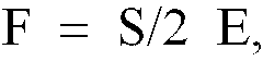
- Verfahren nach Anspruch 2 wobei:E in etwa 1 m ist; undS in etwa 2 m/s beträgt.
- Verfahren nach einem der Ansprüche 1 bis 3, wobei zusätzliche Daten bereitgestellt sind, welche durch einen stationären Magnetsensor gemessen sind, wobei die zusätzlichen Daten temporäre Veränderungen in den Feldern andeuten, welche Frequenzen unterhalb der Abtrennfrequenz haben, und wobei das Verfahren den zusätzlichen Schritt des Abziehens der zusätzlichen Daten von dem Signal, welches die Untersuchungsdaten repräsentiert, oder der ersten Komponente davon umfaßt, um somit in signifikanter Weise die Wirkung jeglicher temporärer Niederfrequenzfeldveränderungen, welche während der Ermittlung auftreten von dem Signal, welches das sich räumlich verändernde Magnetfeld repräsentiert zu reduzieren oder zu entfernen.
- Verfahren nach einem der Ansprüche 1 bis 4, wobei die erste Signalkomponente an Punkten, welche regelmäßige vorbestimmte Durchquerungsabstände repräsentieren, welche in etwa gleich zu oder geringer sind als die Detektorhöhe sind, erneut aufgezeichnet wird.
- Verfahren zum Verarbeiten von Untersuchungsdaten, gemäß einem der Ansprüche 1, 2, 3 oder 5, wobei die Durchquerung des Untersuchungsbereiches mit einem portablen Magnetdetektor durchgeführt wird, und die Verarbeitung gleichzeitig mit der Durchquerung durchgeführt wird.
- Verfahren nach Anspruch 6, zusätzlich umfassend die Schritte des Bereitstellens eines stationären Magnetsensors, Messen der temporären Niederfrequenzveränderungen in den Feldern und Subtrahieren eines Ausgabesignals des stationären Sensors von der ersten Signalkomponente, um somit in signifikanter Weise die Wirkung von jeglichen temporären Niederfrequenzfeldveränderungen, welche während der Ermittlung auftreten von dem Signal, welches das sich räumlich verändernde Magnetfeld repräsentiert zu vermindern oder zu entfernen.
- Verfahren nach einem der Ansprüche 1 bis 7, zusätzlich umfassend die Schritte des Bereitstellens eines künstlich induzierten Magnetfeldes in dem Untersuchungsbereich unter Verwendung eines künstlichen Signales von einer Frequenz, welche größer als die Abtrennfrequenz ist, und des Messens des künstlich induzierten Feldes als die zweite Komponente.
- Vorrichtung zur subterranen Ermittlung umfassend einen portablen Magnetdetektor um ein Signal auszugeben, welches umfaßt, eine erste Signalkomponente mit einem Frequenzbereich, welcher vorwiegend unterhalb einer vorbestimmten Abtrennfrequenz liegt und eine zweite Signalkomponente mit einem Frequenzbereich, welcher vorwiegend oberhalb der vorbestimmten Abtrennfrequenz liegt;eine Signalverarbeitungseinrichtung, welche angeordnet ist, um ein Signal von dem portablen Magnetdetektor zu empfangen, wobei die Verarbeitungseinrichtung angeordnet ist, um die erste und die zweite Signalkomponente zu trennen und um jede Komponente aufzuzeichnen, wobei die ausgewählte Abtrennfrequenz bestimmt ist durch eine vorbestimmte maximale Durchquerungsgeschwindigkeitund durch die Betriebshöhe des Detektors.
- Vorrichtung nach Anspruch 9, worin die Abtrennfrequenz-Auswahleinrichtung angeordnet ist, um auf eine Frequenz F derart eingestellt zu werden, daß

- Vorrichtung nach Anspruch 10, wobei:E in etwa 1 m ist; undS in etwa 2 m/s beträgt.
- Vorrichtung nach Anspruch 9, 10 oder 11, des weiteren umfassend eine integrierte Verarbeitungsausrüstung, welche angeordnet ist, um die getrennten ersten und zweiten Signalkomponenten und das durchquerte Abstandssignal zu empfangen und zum Verstärken, Verarbeiten und Sichern der getrennten Information in einer Speichereinrichtung, und zwar in Echtzeit.
- Vorrichtung nach einem der Ansprüche 9 bis 12, des weiteren umfassend eine felderzeugende Einrichtung, angeordnet um künstlich ein sich temporär veränderndes elektromagnetisches Feld in dem Untersuchungsbereich zu induzieren, wobei das sich zeitlich verändernde Feld der zweiten gemessenen Signalkomponente entspricht.
- Vorrichtung nach einem der Ansprüche 9 bis 13, des weiteren umfassend eine stationäre magnetische Detektoreinrichtung, um temporäre Magnetund Elektromagnetfeldveränderungen zu messen, und Verarbeitungseinrichtungen, um die durch den stationären Detektor gemessenen Signale von der ersten Signalkomponente abzuziehen.
- Vorrichtung nach einem der Ansprüche 9 bis 14, des weiteren umfassend eine integrierte Einrichtung zum Messen des durchquerten Abstandes und zum kontinuierlichen Bereitstellen eines durchquerten Abstandsreferenzsignales, welches zu der Verarbeitungseinrichtung ausgegeben wird.
- Vorrichtung nach Anspruch 15, des weiteren umfassend eine integrierte Verarbeitungsausrüstung, welche die getrennten Signale und das durchquerte Abstandssignal empfängt und angepaßt ist zum Verstärken, Verarbeiten und Speichern der getrennten bzw. aufgeteilten Information in Echtzeit.
- Vorrichtung nach einem der Ansprüche 9 bis 16, des weiteren umfassend ein Fahrzeug, auf welchem der Magnetdetektor montiert ist, wobei das Fahrzeug angeordnet ist, um den Magnetdetektor über einem Untersuchungsbereich bei einer vorbestimmten konstanten Geschwindigkeit und bei der vorbestimmten konstanten Detektorhöhe zu transportieren.
Applications Claiming Priority (3)
| Application Number | Priority Date | Filing Date | Title |
|---|---|---|---|
| AUPK051690 | 1990-06-06 | ||
| AU516/90 | 1990-06-06 | ||
| PCT/AU1991/000238 WO1991019210A1 (en) | 1990-06-06 | 1991-06-03 | Sub-audio magnetics instrument |
Publications (3)
| Publication Number | Publication Date |
|---|---|
| EP0532604A1 EP0532604A1 (de) | 1993-03-24 |
| EP0532604A4 EP0532604A4 (en) | 1993-06-09 |
| EP0532604B1 true EP0532604B1 (de) | 1996-04-03 |
Family
ID=3774741
Family Applications (1)
| Application Number | Title | Priority Date | Filing Date |
|---|---|---|---|
| EP91910906A Expired - Lifetime EP0532604B1 (de) | 1990-06-06 | 1991-06-03 | Infraakustischmagnetisches messinstrument |
Country Status (12)
| Country | Link |
|---|---|
| US (1) | US5444374A (de) |
| EP (1) | EP0532604B1 (de) |
| JP (1) | JP2939334B2 (de) |
| AT (1) | ATE136371T1 (de) |
| AU (1) | AU652374B2 (de) |
| CA (1) | CA2084656C (de) |
| DE (1) | DE69118532T2 (de) |
| DK (1) | DK0532604T3 (de) |
| ES (1) | ES2088005T3 (de) |
| GR (1) | GR3020447T3 (de) |
| RU (1) | RU2095828C1 (de) |
| WO (1) | WO1991019210A1 (de) |
Families Citing this family (15)
| Publication number | Priority date | Publication date | Assignee | Title |
|---|---|---|---|---|
| AUPM352394A0 (en) * | 1994-01-25 | 1994-02-17 | University Of New England, The | Method of interpreting potential field data |
| AU681492B2 (en) * | 1994-01-25 | 1997-08-28 | Geophysical Technology Limited | Method of interpreting potential field data |
| AUPR723201A0 (en) * | 2001-08-23 | 2001-09-13 | M.I.M. Exploration Pty. Ltd. | A data aquisition system |
| AU2002300628B2 (en) * | 2001-08-23 | 2007-11-08 | Xstrata Copper Exploration Pty Ltd | A data aquisition system |
| RU2261424C1 (ru) * | 2004-03-17 | 2005-09-27 | Государственное образовательное учреждение высшего профессионального образования Красноярский государственный технический университет (КГТУ) | Система для определения координат трассы и координат дефектов подземного трубопровода |
| US20100026304A1 (en) * | 2007-01-31 | 2010-02-04 | Andrew Duncan | Method and Apparatus for Analysing Geological Features |
| NO328811B1 (no) * | 2007-12-21 | 2010-05-18 | Advanced Hydrocarbon Mapping A | Framgangsmate og apparat for hurtig kartlegging av submarine hydrokarbonreservoarer |
| CN101556340B (zh) * | 2008-04-10 | 2011-08-03 | 中国石油集团东方地球物理勘探有限责任公司 | 三维小面元大地电磁连续阵列数据采集方法 |
| US8686723B2 (en) * | 2010-03-22 | 2014-04-01 | Schlumberger Technology Corporation | Determining the larmor frequency for NMR tools |
| CN102590875B (zh) * | 2012-03-01 | 2013-12-18 | 赤峰宏远地质勘查有限公司唐山迁西分公司 | 遥感物探系统和遥感物探方法 |
| US9316758B2 (en) | 2013-05-29 | 2016-04-19 | Liquid Robotics Oil and Gas LLC | Earth surveying for improved drilling applications |
| US11061160B1 (en) * | 2015-07-24 | 2021-07-13 | Doc Mapping, L.L.C. | System and methods of mapping buried pipes underwater |
| CN105204072B (zh) * | 2015-09-16 | 2017-08-29 | 吉林大学 | 高密度电法仪器中的磁电极及测量方法 |
| CN108254271B (zh) * | 2016-12-28 | 2020-10-30 | 深圳市弗赛特科技股份有限公司 | 一种疲劳试验测量方法 |
| RU2677954C1 (ru) * | 2017-01-10 | 2019-01-22 | Российская Федерация, от имени которой выступает Министерство обороны Российской Федерации Федеральное государственное бюджетное учреждение "48 Центральный научно-исследовательский институт" Министерства обороны Российской Федерации | Способ мониторинга стадии культивирования в технологии чумной вакцины |
Family Cites Families (11)
| Publication number | Priority date | Publication date | Assignee | Title |
|---|---|---|---|---|
| US2777112A (en) * | 1953-11-12 | 1957-01-08 | United Geophysical Corp | Magnetometer survey apparatus |
| US3889181A (en) * | 1974-03-08 | 1975-06-10 | Us Army | Magnetic system for discriminating between vehicles and personnel based upon their characteristic frequency signatures |
| US4021725A (en) | 1976-03-05 | 1977-05-03 | The United States Of America As Represented By The Secretary Of The Navy | Mobile mine detection system having plural color display |
| US5025218A (en) * | 1979-04-23 | 1991-06-18 | The United States Of America As Represented By The Secretary Of The Navy | Pulsed field system for detecting the presence of a target in a subsurface environment |
| CA1133058A (en) * | 1982-02-18 | 1982-10-05 | Geonics Limited | Electromagnetic geophysical surveying system |
| US5030913A (en) * | 1982-06-21 | 1991-07-09 | The United States Of America As Represented By The Secretary Of The Navy | Multiple sensor magnetometer with temporal noise rejection and controllable spatial response on a moving platform |
| US4814711A (en) * | 1984-04-05 | 1989-03-21 | Deseret Research, Inc. | Survey system and method for real time collection and processing of geophysicals data using signals from a global positioning satellite network |
| US4675606A (en) | 1985-07-29 | 1987-06-23 | Suman Ganguly | Magnetometers for detecting metallic objects in earth's magnetic field |
| US4727329A (en) | 1986-02-19 | 1988-02-23 | Atlantic Richfield Company | Method and system for measuring displacement of buried fluid transmission pipelines |
| US4939460A (en) | 1987-12-14 | 1990-07-03 | Patla Louis J | Indigenous electromagnetic radiation based method for detecting geologic deposits |
| US5175500A (en) * | 1990-08-01 | 1992-12-29 | Geonics Limited | Method and apparatus for surveying terrain resistivity utilizing available VFL electromagnetic fields |
-
1991
- 1991-06-03 EP EP91910906A patent/EP0532604B1/de not_active Expired - Lifetime
- 1991-06-03 US US07/955,875 patent/US5444374A/en not_active Expired - Lifetime
- 1991-06-03 DE DE69118532T patent/DE69118532T2/de not_active Expired - Fee Related
- 1991-06-03 ES ES91910906T patent/ES2088005T3/es not_active Expired - Lifetime
- 1991-06-03 AT AT91910906T patent/ATE136371T1/de not_active IP Right Cessation
- 1991-06-03 AU AU80827/91A patent/AU652374B2/en not_active Ceased
- 1991-06-03 CA CA002084656A patent/CA2084656C/en not_active Expired - Lifetime
- 1991-06-03 WO PCT/AU1991/000238 patent/WO1991019210A1/en not_active Ceased
- 1991-06-03 RU RU92016530/25A patent/RU2095828C1/ru not_active IP Right Cessation
- 1991-06-03 DK DK91910906.6T patent/DK0532604T3/da not_active Application Discontinuation
- 1991-06-03 JP JP3515389A patent/JP2939334B2/ja not_active Expired - Fee Related
-
1996
- 1996-07-03 GR GR960401820T patent/GR3020447T3/el unknown
Also Published As
| Publication number | Publication date |
|---|---|
| DE69118532D1 (de) | 1996-05-09 |
| ATE136371T1 (de) | 1996-04-15 |
| JP2939334B2 (ja) | 1999-08-25 |
| CA2084656C (en) | 1999-03-16 |
| CA2084656A1 (en) | 1991-12-07 |
| ES2088005T3 (es) | 1996-08-01 |
| EP0532604A4 (en) | 1993-06-09 |
| DE69118532T2 (de) | 1996-10-31 |
| DK0532604T3 (da) | 1996-07-29 |
| AU652374B2 (en) | 1994-08-25 |
| RU2095828C1 (ru) | 1997-11-10 |
| GR3020447T3 (en) | 1996-10-31 |
| JPH06500172A (ja) | 1994-01-06 |
| US5444374A (en) | 1995-08-22 |
| WO1991019210A1 (en) | 1991-12-12 |
| EP0532604A1 (de) | 1993-03-24 |
| AU8082791A (en) | 1991-12-31 |
Similar Documents
| Publication | Publication Date | Title |
|---|---|---|
| Won et al. | GEM-2: A new multifrequency electromagnetic sensor | |
| Palacky et al. | Airborne electromagnetic methods | |
| CA2144546C (en) | Method and apparatus for passively detecting the depth and location of a spatial or temporal anomaly | |
| Haines et al. | Seismoelectric imaging of shallow targets | |
| EP0532604B1 (de) | Infraakustischmagnetisches messinstrument | |
| US6914433B2 (en) | Detection of subsurface resistivity contrasts with application to location of fluids | |
| CA1210063A (en) | Method and apparatus for extended lateral range electrical conductivity logging | |
| US20100026304A1 (en) | Method and Apparatus for Analysing Geological Features | |
| EP0125741B1 (de) | Detektor für vergrabene Gegenstände | |
| US5654637A (en) | Method for detecting buried high conductivity objects including scaling of voltages for eliminating noise of a particular depth | |
| Cattach et al. | Sub-Audio Magnetics (SAM)—A High Resolution Technique for Simultaneously Mapping Electrical and Magnetic Properties1 | |
| US4095169A (en) | Method for locating discontinuities in the electrical conductivity of the sub-soil using a plurality of magnetic detectors in a predetermined spatial arrangement | |
| RU2093863C1 (ru) | Способ электромагнитного зондирования земной коры с использованием нормированных источников поля | |
| US3085197A (en) | Inductor survey apparatus and method for determining presence of oil bearing substrata | |
| RU2732545C1 (ru) | Способ геологической разведки минералов | |
| US2636924A (en) | Method of geophysical exploration | |
| GB2135460A (en) | Detecting hidden objects | |
| Dupuis et al. | Design of field instrumentation and noise removal techniques for seismoelectric measurements | |
| Whiteford | Assessment of the audio-magnetotelluric method for geothermal resistivity surveying | |
| Duncan | Advances in ground and borehole EM survey technology to 2017 | |
| Becker | Airborne resistivity mapping | |
| Waff | Electrical resistivity imaging of groundwater systems using natural and controlled source magnetotellurics | |
| EP0017682A2 (de) | Verfahren und System für geophysikalische Induktions-Untersuchungen | |
| RU2059270C1 (ru) | Способ определения фазы геоэлектрического импеданса | |
| Goubau | Geophysical applications of SQUIDs |
Legal Events
| Date | Code | Title | Description |
|---|---|---|---|
| PUAI | Public reference made under article 153(3) epc to a published international application that has entered the european phase |
Free format text: ORIGINAL CODE: 0009012 |
|
| 17P | Request for examination filed |
Effective date: 19921204 |
|
| AK | Designated contracting states |
Kind code of ref document: A1 Designated state(s): AT BE CH DE DK ES FR GB GR IT LI LU NL SE |
|
| A4 | Supplementary search report drawn up and despatched |
Effective date: 19930419 |
|
| AK | Designated contracting states |
Kind code of ref document: A4 Designated state(s): AT BE CH DE DK ES FR GB GR IT LI LU NL SE |
|
| 17Q | First examination report despatched |
Effective date: 19941220 |
|
| GRAA | (expected) grant |
Free format text: ORIGINAL CODE: 0009210 |
|
| AK | Designated contracting states |
Kind code of ref document: B1 Designated state(s): AT BE CH DE DK ES FR GB GR IT LI LU NL SE |
|
| REF | Corresponds to: |
Ref document number: 136371 Country of ref document: AT Date of ref document: 19960415 Kind code of ref document: T |
|
| REF | Corresponds to: |
Ref document number: 69118532 Country of ref document: DE Date of ref document: 19960509 |
|
| ITF | It: translation for a ep patent filed | ||
| REG | Reference to a national code |
Ref country code: ES Ref legal event code: BA2A Ref document number: 2088005 Country of ref document: ES Kind code of ref document: T3 |
|
| ET | Fr: translation filed | ||
| REG | Reference to a national code |
Ref country code: DK Ref legal event code: T3 |
|
| REG | Reference to a national code |
Ref country code: CH Ref legal event code: NV Representative=s name: SAEGER & PARTNER |
|
| REG | Reference to a national code |
Ref country code: ES Ref legal event code: FG2A Ref document number: 2088005 Country of ref document: ES Kind code of ref document: T3 |
|
| REG | Reference to a national code |
Ref country code: GR Ref legal event code: FG4A Free format text: 3020447 |
|
| PLBE | No opposition filed within time limit |
Free format text: ORIGINAL CODE: 0009261 |
|
| STAA | Information on the status of an ep patent application or granted ep patent |
Free format text: STATUS: NO OPPOSITION FILED WITHIN TIME LIMIT |
|
| 26N | No opposition filed | ||
| REG | Reference to a national code |
Ref country code: GB Ref legal event code: 732E |
|
| REG | Reference to a national code |
Ref country code: CH Ref legal event code: PUE Owner name: UNE PARTNERSHIPS PTY LTD. TRANSFER- GEOPHYSICAL TE Ref country code: CH Ref legal event code: PFA Free format text: UNIVERSITY PARTNERSHIPS PTY. LIMITED TRANSFER- UNE PARTNERSHIPS PTY LTD. |
|
| NLS | Nl: assignments of ep-patents |
Owner name: GEOPHYSICAL TECHNOLOGY LIMITED |
|
| NLT1 | Nl: modifications of names registered in virtue of documents presented to the patent office pursuant to art. 16 a, paragraph 1 |
Owner name: UNE PARTNERSHIPS PTY LTD |
|
| REG | Reference to a national code |
Ref country code: FR Ref legal event code: TP |
|
| REG | Reference to a national code |
Ref country code: ES Ref legal event code: PC2A |
|
| REG | Reference to a national code |
Ref country code: GB Ref legal event code: IF02 |
|
| PGFP | Annual fee paid to national office [announced via postgrant information from national office to epo] |
Ref country code: SE Payment date: 20020611 Year of fee payment: 12 |
|
| PGFP | Annual fee paid to national office [announced via postgrant information from national office to epo] |
Ref country code: AT Payment date: 20020612 Year of fee payment: 12 |
|
| PGFP | Annual fee paid to national office [announced via postgrant information from national office to epo] |
Ref country code: DK Payment date: 20020614 Year of fee payment: 12 |
|
| PGFP | Annual fee paid to national office [announced via postgrant information from national office to epo] |
Ref country code: CH Payment date: 20020617 Year of fee payment: 12 |
|
| PGFP | Annual fee paid to national office [announced via postgrant information from national office to epo] |
Ref country code: LU Payment date: 20020620 Year of fee payment: 12 |
|
| PGFP | Annual fee paid to national office [announced via postgrant information from national office to epo] |
Ref country code: ES Payment date: 20020624 Year of fee payment: 12 |
|
| PGFP | Annual fee paid to national office [announced via postgrant information from national office to epo] |
Ref country code: GR Payment date: 20020626 Year of fee payment: 12 |
|
| PGFP | Annual fee paid to national office [announced via postgrant information from national office to epo] |
Ref country code: NL Payment date: 20020628 Year of fee payment: 12 |
|
| PGFP | Annual fee paid to national office [announced via postgrant information from national office to epo] |
Ref country code: BE Payment date: 20020821 Year of fee payment: 12 |
|
| PG25 | Lapsed in a contracting state [announced via postgrant information from national office to epo] |
Ref country code: LU Free format text: LAPSE BECAUSE OF NON-PAYMENT OF DUE FEES Effective date: 20030603 Ref country code: AT Free format text: LAPSE BECAUSE OF NON-PAYMENT OF DUE FEES Effective date: 20030603 |
|
| PG25 | Lapsed in a contracting state [announced via postgrant information from national office to epo] |
Ref country code: SE Free format text: LAPSE BECAUSE OF NON-PAYMENT OF DUE FEES Effective date: 20030604 Ref country code: ES Free format text: LAPSE BECAUSE OF NON-PAYMENT OF DUE FEES Effective date: 20030604 |
|
| PG25 | Lapsed in a contracting state [announced via postgrant information from national office to epo] |
Ref country code: LI Free format text: LAPSE BECAUSE OF NON-PAYMENT OF DUE FEES Effective date: 20030630 Ref country code: DK Free format text: LAPSE BECAUSE OF NON-PAYMENT OF DUE FEES Effective date: 20030630 Ref country code: CH Free format text: LAPSE BECAUSE OF NON-PAYMENT OF DUE FEES Effective date: 20030630 Ref country code: BE Free format text: LAPSE BECAUSE OF NON-PAYMENT OF DUE FEES Effective date: 20030630 |
|
| BERE | Be: lapsed |
Owner name: *GEOPHYSICAL TECHNOLOGY LTD Effective date: 20030630 |
|
| PG25 | Lapsed in a contracting state [announced via postgrant information from national office to epo] |
Ref country code: NL Free format text: LAPSE BECAUSE OF NON-PAYMENT OF DUE FEES Effective date: 20040101 |
|
| PG25 | Lapsed in a contracting state [announced via postgrant information from national office to epo] |
Ref country code: GR Free format text: LAPSE BECAUSE OF NON-PAYMENT OF DUE FEES Effective date: 20040107 |
|
| EUG | Se: european patent has lapsed | ||
| REG | Reference to a national code |
Ref country code: DK Ref legal event code: EBP |
|
| REG | Reference to a national code |
Ref country code: CH Ref legal event code: PL |
|
| NLV4 | Nl: lapsed or anulled due to non-payment of the annual fee |
Effective date: 20040101 |
|
| PGFP | Annual fee paid to national office [announced via postgrant information from national office to epo] |
Ref country code: GB Payment date: 20040602 Year of fee payment: 14 |
|
| PGFP | Annual fee paid to national office [announced via postgrant information from national office to epo] |
Ref country code: FR Payment date: 20040608 Year of fee payment: 14 |
|
| PGFP | Annual fee paid to national office [announced via postgrant information from national office to epo] |
Ref country code: DE Payment date: 20040610 Year of fee payment: 14 |
|
| REG | Reference to a national code |
Ref country code: ES Ref legal event code: FD2A Effective date: 20030604 |
|
| PG25 | Lapsed in a contracting state [announced via postgrant information from national office to epo] |
Ref country code: IT Free format text: LAPSE BECAUSE OF NON-PAYMENT OF DUE FEES Effective date: 20050603 Ref country code: GB Free format text: LAPSE BECAUSE OF NON-PAYMENT OF DUE FEES Effective date: 20050603 |
|
| PG25 | Lapsed in a contracting state [announced via postgrant information from national office to epo] |
Ref country code: DE Free format text: LAPSE BECAUSE OF NON-PAYMENT OF DUE FEES Effective date: 20060103 |
|
| PG25 | Lapsed in a contracting state [announced via postgrant information from national office to epo] |
Ref country code: FR Free format text: LAPSE BECAUSE OF NON-PAYMENT OF DUE FEES Effective date: 20060228 |
|
| GBPC | Gb: european patent ceased through non-payment of renewal fee |
Effective date: 20050603 |
|
| REG | Reference to a national code |
Ref country code: FR Ref legal event code: ST Effective date: 20060228 |