EP0532814A1 - Vorrichtung zur Behandlung von Fluiden mit einer Adsorptionsstruktur aus überlagerten Schichten, die voneinander einen Abstand besitzen, und Regeneration durch den Jouleeffekt - Google Patents
Vorrichtung zur Behandlung von Fluiden mit einer Adsorptionsstruktur aus überlagerten Schichten, die voneinander einen Abstand besitzen, und Regeneration durch den Jouleeffekt Download PDFInfo
- Publication number
- EP0532814A1 EP0532814A1 EP91460043A EP91460043A EP0532814A1 EP 0532814 A1 EP0532814 A1 EP 0532814A1 EP 91460043 A EP91460043 A EP 91460043A EP 91460043 A EP91460043 A EP 91460043A EP 0532814 A1 EP0532814 A1 EP 0532814A1
- Authority
- EP
- European Patent Office
- Prior art keywords
- adsorbent material
- layers
- fluid
- desorption
- treated
- Prior art date
- Legal status (The legal status is an assumption and is not a legal conclusion. Google has not performed a legal analysis and makes no representation as to the accuracy of the status listed.)
- Granted
Links
- 239000012530 fluid Substances 0.000 title claims abstract description 55
- 230000000694 effects Effects 0.000 title claims abstract description 14
- 230000008929 regeneration Effects 0.000 title claims description 21
- 238000011069 regeneration method Methods 0.000 title claims description 21
- 238000001179 sorption measurement Methods 0.000 title description 9
- 239000003463 adsorbent Substances 0.000 claims abstract description 83
- 239000000463 material Substances 0.000 claims abstract description 76
- 238000011282 treatment Methods 0.000 claims abstract description 48
- 239000000470 constituent Substances 0.000 claims abstract description 25
- XLYOFNOQVPJJNP-UHFFFAOYSA-N water Substances O XLYOFNOQVPJJNP-UHFFFAOYSA-N 0.000 claims abstract description 11
- 239000004020 conductor Substances 0.000 claims abstract description 7
- 238000003795 desorption Methods 0.000 claims description 37
- 239000004744 fabric Substances 0.000 claims description 21
- 239000007789 gas Substances 0.000 claims description 21
- 239000002245 particle Substances 0.000 claims description 10
- 239000000835 fiber Substances 0.000 claims description 9
- 238000000605 extraction Methods 0.000 claims description 7
- 238000009833 condensation Methods 0.000 claims description 6
- 230000005494 condensation Effects 0.000 claims description 6
- 239000012159 carrier gas Substances 0.000 claims description 5
- 239000002904 solvent Substances 0.000 claims description 5
- 239000006260 foam Substances 0.000 claims description 4
- 239000012528 membrane Substances 0.000 claims description 4
- 239000011261 inert gas Substances 0.000 claims description 3
- 238000000746 purification Methods 0.000 claims description 3
- -1 felts Substances 0.000 claims description 2
- VNWKTOKETHGBQD-UHFFFAOYSA-N methane Chemical class C VNWKTOKETHGBQD-UHFFFAOYSA-N 0.000 claims description 2
- 230000000737 periodic effect Effects 0.000 claims description 2
- 239000010410 layer Substances 0.000 description 54
- OKTJSMMVPCPJKN-UHFFFAOYSA-N Carbon Chemical compound [C] OKTJSMMVPCPJKN-UHFFFAOYSA-N 0.000 description 40
- 150000001875 compounds Chemical class 0.000 description 7
- 239000011229 interlayer Substances 0.000 description 7
- 238000010438 heat treatment Methods 0.000 description 6
- 238000009434 installation Methods 0.000 description 4
- 238000007664 blowing Methods 0.000 description 3
- 238000001914 filtration Methods 0.000 description 3
- 238000004519 manufacturing process Methods 0.000 description 3
- 238000000034 method Methods 0.000 description 3
- 239000000126 substance Substances 0.000 description 3
- UOCLXMDMGBRAIB-UHFFFAOYSA-N 1,1,1-trichloroethane Chemical compound CC(Cl)(Cl)Cl UOCLXMDMGBRAIB-UHFFFAOYSA-N 0.000 description 2
- IJGRMHOSHXDMSA-UHFFFAOYSA-N Atomic nitrogen Chemical compound N#N IJGRMHOSHXDMSA-UHFFFAOYSA-N 0.000 description 2
- 125000000316 D-glutamoyl group Chemical group [H]N([H])[C@@]([H])(C(=O)[*])C([H])([H])C([H])([H])C(N([H])[H])=O 0.000 description 2
- 229910052799 carbon Inorganic materials 0.000 description 2
- 238000006243 chemical reaction Methods 0.000 description 2
- 238000010586 diagram Methods 0.000 description 2
- 239000000839 emulsion Substances 0.000 description 2
- 229910002804 graphite Inorganic materials 0.000 description 2
- 239000010439 graphite Substances 0.000 description 2
- 230000007935 neutral effect Effects 0.000 description 2
- 239000003960 organic solvent Substances 0.000 description 2
- 229920002239 polyacrylonitrile Polymers 0.000 description 2
- 230000000717 retained effect Effects 0.000 description 2
- 125000006850 spacer group Chemical group 0.000 description 2
- 238000012546 transfer Methods 0.000 description 2
- WECIKJKLCDCIMY-UHFFFAOYSA-N 2-chloro-n-(2-cyanoethyl)acetamide Chemical compound ClCC(=O)NCCC#N WECIKJKLCDCIMY-UHFFFAOYSA-N 0.000 description 1
- 241000894006 Bacteria Species 0.000 description 1
- 239000002028 Biomass Substances 0.000 description 1
- DKPFZGUDAPQIHT-UHFFFAOYSA-N Butyl acetate Natural products CCCCOC(C)=O DKPFZGUDAPQIHT-UHFFFAOYSA-N 0.000 description 1
- 229920000049 Carbon (fiber) Polymers 0.000 description 1
- LFQSCWFLJHTTHZ-UHFFFAOYSA-N Ethanol Chemical compound CCO LFQSCWFLJHTTHZ-UHFFFAOYSA-N 0.000 description 1
- 241001282135 Poromitra oscitans Species 0.000 description 1
- XSTXAVWGXDQKEL-UHFFFAOYSA-N Trichloroethylene Chemical group ClC=C(Cl)Cl XSTXAVWGXDQKEL-UHFFFAOYSA-N 0.000 description 1
- 206010048232 Yawning Diseases 0.000 description 1
- 230000004913 activation Effects 0.000 description 1
- 150000001298 alcohols Chemical class 0.000 description 1
- 210000004534 cecum Anatomy 0.000 description 1
- 239000012809 cooling fluid Substances 0.000 description 1
- 230000029087 digestion Effects 0.000 description 1
- 238000007599 discharging Methods 0.000 description 1
- 229940082150 encore Drugs 0.000 description 1
- FUZZWVXGSFPDMH-UHFFFAOYSA-N hexanoic acid Chemical compound CCCCCC(O)=O FUZZWVXGSFPDMH-UHFFFAOYSA-N 0.000 description 1
- 238000011065 in-situ storage Methods 0.000 description 1
- 238000002347 injection Methods 0.000 description 1
- 239000007924 injection Substances 0.000 description 1
- 150000002576 ketones Chemical class 0.000 description 1
- 239000007788 liquid Substances 0.000 description 1
- 230000014759 maintenance of location Effects 0.000 description 1
- 229910052757 nitrogen Inorganic materials 0.000 description 1
- 238000012856 packing Methods 0.000 description 1
- 238000005191 phase separation Methods 0.000 description 1
- 150000002989 phenols Chemical class 0.000 description 1
- 238000012545 processing Methods 0.000 description 1
- 230000001737 promoting effect Effects 0.000 description 1
- 230000001172 regenerating effect Effects 0.000 description 1
- 230000002787 reinforcement Effects 0.000 description 1
- 238000011160 research Methods 0.000 description 1
- 229920006395 saturated elastomer Polymers 0.000 description 1
- 238000000926 separation method Methods 0.000 description 1
- 239000002002 slurry Substances 0.000 description 1
- 239000000243 solution Substances 0.000 description 1
- 231100000331 toxic Toxicity 0.000 description 1
- 230000002588 toxic effect Effects 0.000 description 1
- 231100000419 toxicity Toxicity 0.000 description 1
- 230000001988 toxicity Effects 0.000 description 1
- 239000002912 waste gas Substances 0.000 description 1
- 238000004804 winding Methods 0.000 description 1
Images

Classifications
-
- B—PERFORMING OPERATIONS; TRANSPORTING
- B01—PHYSICAL OR CHEMICAL PROCESSES OR APPARATUS IN GENERAL
- B01J—CHEMICAL OR PHYSICAL PROCESSES, e.g. CATALYSIS OR COLLOID CHEMISTRY; THEIR RELEVANT APPARATUS
- B01J20/00—Solid sorbent compositions or filter aid compositions; Sorbents for chromatography; Processes for preparing, regenerating or reactivating thereof
- B01J20/30—Processes for preparing, regenerating, or reactivating
- B01J20/34—Regenerating or reactivating
- B01J20/3441—Regeneration or reactivation by electric current, ultrasound or irradiation, e.g. electromagnetic radiation such as X-rays, UV, light, microwaves
-
- B—PERFORMING OPERATIONS; TRANSPORTING
- B01—PHYSICAL OR CHEMICAL PROCESSES OR APPARATUS IN GENERAL
- B01D—SEPARATION
- B01D15/00—Separating processes involving the treatment of liquids with solid sorbents; Apparatus therefor
-
- B—PERFORMING OPERATIONS; TRANSPORTING
- B01—PHYSICAL OR CHEMICAL PROCESSES OR APPARATUS IN GENERAL
- B01D—SEPARATION
- B01D53/00—Separation of gases or vapours; Recovering vapours of volatile solvents from gases; Chemical or biological purification of waste gases, e.g. engine exhaust gases, smoke, fumes, flue gases, aerosols
- B01D53/02—Separation of gases or vapours; Recovering vapours of volatile solvents from gases; Chemical or biological purification of waste gases, e.g. engine exhaust gases, smoke, fumes, flue gases, aerosols by adsorption, e.g. preparative gas chromatography
- B01D53/04—Separation of gases or vapours; Recovering vapours of volatile solvents from gases; Chemical or biological purification of waste gases, e.g. engine exhaust gases, smoke, fumes, flue gases, aerosols by adsorption, e.g. preparative gas chromatography with stationary adsorbents
- B01D53/0407—Constructional details of adsorbing systems
- B01D53/0438—Cooling or heating systems
-
- B—PERFORMING OPERATIONS; TRANSPORTING
- B01—PHYSICAL OR CHEMICAL PROCESSES OR APPARATUS IN GENERAL
- B01D—SEPARATION
- B01D53/00—Separation of gases or vapours; Recovering vapours of volatile solvents from gases; Chemical or biological purification of waste gases, e.g. engine exhaust gases, smoke, fumes, flue gases, aerosols
- B01D53/02—Separation of gases or vapours; Recovering vapours of volatile solvents from gases; Chemical or biological purification of waste gases, e.g. engine exhaust gases, smoke, fumes, flue gases, aerosols by adsorption, e.g. preparative gas chromatography
- B01D53/04—Separation of gases or vapours; Recovering vapours of volatile solvents from gases; Chemical or biological purification of waste gases, e.g. engine exhaust gases, smoke, fumes, flue gases, aerosols by adsorption, e.g. preparative gas chromatography with stationary adsorbents
- B01D53/0407—Constructional details of adsorbing systems
- B01D53/0446—Means for feeding or distributing gases
-
- B—PERFORMING OPERATIONS; TRANSPORTING
- B01—PHYSICAL OR CHEMICAL PROCESSES OR APPARATUS IN GENERAL
- B01D—SEPARATION
- B01D2253/00—Adsorbents used in seperation treatment of gases and vapours
- B01D2253/10—Inorganic adsorbents
- B01D2253/102—Carbon
-
- B—PERFORMING OPERATIONS; TRANSPORTING
- B01—PHYSICAL OR CHEMICAL PROCESSES OR APPARATUS IN GENERAL
- B01D—SEPARATION
- B01D2253/00—Adsorbents used in seperation treatment of gases and vapours
- B01D2253/20—Organic adsorbents
- B01D2253/202—Polymeric adsorbents
-
- B—PERFORMING OPERATIONS; TRANSPORTING
- B01—PHYSICAL OR CHEMICAL PROCESSES OR APPARATUS IN GENERAL
- B01D—SEPARATION
- B01D2253/00—Adsorbents used in seperation treatment of gases and vapours
- B01D2253/30—Physical properties of adsorbents
- B01D2253/34—Specific shapes
-
- B—PERFORMING OPERATIONS; TRANSPORTING
- B01—PHYSICAL OR CHEMICAL PROCESSES OR APPARATUS IN GENERAL
- B01D—SEPARATION
- B01D2257/00—Components to be removed
- B01D2257/20—Halogens or halogen compounds
- B01D2257/206—Organic halogen compounds
- B01D2257/2064—Chlorine
-
- B—PERFORMING OPERATIONS; TRANSPORTING
- B01—PHYSICAL OR CHEMICAL PROCESSES OR APPARATUS IN GENERAL
- B01D—SEPARATION
- B01D2257/00—Components to be removed
- B01D2257/70—Organic compounds not provided for in groups B01D2257/00 - B01D2257/602
- B01D2257/708—Volatile organic compounds V.O.C.'s
-
- B—PERFORMING OPERATIONS; TRANSPORTING
- B01—PHYSICAL OR CHEMICAL PROCESSES OR APPARATUS IN GENERAL
- B01D—SEPARATION
- B01D2257/00—Components to be removed
- B01D2257/93—Toxic compounds not provided for in groups B01D2257/00 - B01D2257/708
-
- B—PERFORMING OPERATIONS; TRANSPORTING
- B01—PHYSICAL OR CHEMICAL PROCESSES OR APPARATUS IN GENERAL
- B01D—SEPARATION
- B01D2259/00—Type of treatment
- B01D2259/40—Further details for adsorption processes and devices
- B01D2259/40083—Regeneration of adsorbents in processes other than pressure or temperature swing adsorption
- B01D2259/40088—Regeneration of adsorbents in processes other than pressure or temperature swing adsorption by heating
- B01D2259/4009—Regeneration of adsorbents in processes other than pressure or temperature swing adsorption by heating using hot gas
-
- B—PERFORMING OPERATIONS; TRANSPORTING
- B01—PHYSICAL OR CHEMICAL PROCESSES OR APPARATUS IN GENERAL
- B01D—SEPARATION
- B01D2259/00—Type of treatment
- B01D2259/40—Further details for adsorption processes and devices
- B01D2259/40083—Regeneration of adsorbents in processes other than pressure or temperature swing adsorption
- B01D2259/40088—Regeneration of adsorbents in processes other than pressure or temperature swing adsorption by heating
- B01D2259/40096—Regeneration of adsorbents in processes other than pressure or temperature swing adsorption by heating by using electrical resistance heating
-
- B—PERFORMING OPERATIONS; TRANSPORTING
- B01—PHYSICAL OR CHEMICAL PROCESSES OR APPARATUS IN GENERAL
- B01D—SEPARATION
- B01D2259/00—Type of treatment
- B01D2259/40—Further details for adsorption processes and devices
- B01D2259/41—Further details for adsorption processes and devices using plural beds of the same adsorbent in series
Definitions
- the field of the invention is that of the treatment of fluids comprising adsorbable constituents.
- the present invention relates to a device for treating fluids, such as air or water for example, loaded with adsorbable constituents, using an adsorbent material.
- the adsorbable constituents can in particular consist of molecules of chemicals, solvents, chlorinated products, etc. present in a liquid, in a gas, or in the air.
- the processing of such fluids is notably carried out in situ in research centers or production units using or manufacturing such products.
- This treatment is for example necessary in order not to reject into the nature highly toxic products such as for example trichlorethylene, trichloroethane, or products based on freon.
- the treatment of the fluid consists, in a known manner, of passing it through a material which adsorbs the adsorbable constituents, thus performing a filtration function, and of discharging the fluid stripped of its polluting constituents, either to make it undergo another operation, or for the reject in nature.
- the adsorbent material may in particular be activated carbon, which is either in the form of grains or in the form of several layers or sheets of fibers stacked on top of each other.
- the regeneration is carried out by injecting water vapor onto the adsorbent material, in order to cause the desorption of the adsorbed products.
- This method has the disadvantage of requiring the use of a boiler for the production of steam.
- regeneration can also be carried out by injection of hot air, but very long regeneration times are observed, with a relatively low percentage of regeneration.
- the European patent document No. 0014749 of the company ACTIVATED CARBON SERVICES LIMITED discloses an activated carbon regeneration device being in the form of grains by means of a heating process material by Joule effect.
- the carbon to be regenerated is loaded into a treatment column, the base of which is formed by an electrode, and covered by another electrode.
- the application of a potential difference between the electrodes generates a current which flows through the carbon to be regenerated, thereby causing it to heat up.
- the adsorbed molecules are desorbed and are removed from the treatment column by blowing a gas or vapor.
- the main drawback of this type of device is that it is specifically dedicated to the regeneration operation, which means that it requires transferring the adsorbent material, saturated with adsorbed constituents, from the filtration installation to the place of regeneration.
- Activated carbon is in the form of mattresses made up of 10 to 30 layers of activated carbon sheets. Each mattress is arranged in a drawer whose bottom consists of electrical resistances and the drawers are offset with respect to each other in a treatment tank. Deflectors channel the fluid to be treated so that each stream of fluid crosses only one of the drawers. The desorption operation is carried out by heating the electrical resistances placed under the mattresses of layers of activated carbon.
- Another drawback of this device is that the desorption is carried out by heating electrical resistances.
- the activated carbon mattresses are therefore heated indirectly so that the desorption operation is relatively long and the percentage of regeneration low.
- the present invention aims in particular to overcome these drawbacks.
- a first objective of the invention is to implement a fluid treatment device allowing both efficient retention of the adsorbable particles present in the fluid in the adsorption phase and a high regeneration rate in the desorption phase. .
- Another objective of the present invention is to promote the distribution and circulation of the particles in the treatment tank where the structure of adsorbent material is placed, so as to increase the efficiency of the adsorption and desorption phases.
- a device for treating fluid in particular air or water charged with at least one adsorbable constituent, of the type comprising a structure of adsorbent material intended to be traversed by a flow of said fluid to be treated so as to adsorb said adsorbable constituent by said adsorbent material, characterized in that said structure of adsorbent material consists of a set of superimposed layers, spaced so as to favor the creation of turbulence between said layers successively crossed by said flow of fluid to be treated.
- said layers consist of fabrics, membranes, fibers, fabrics, felts, foams or any combination of at least two of these materials.
- the essentially two-dimensional configuration of each layer allows good homogeneity of adsorption and desorption by the Joule effect, over the entire layer.
- said adsorbent material is an electrically conductive material.
- said adsorbent material is in the form of at least one sheet of activated carbon fabric.
- At least one of said layers of the structure of adsorbent material is produced by a sheet of fabric, the fibers of which consist of wires of electrically conductive material to which particles of material are agglomerated. adsorbent.
- said structure can advantageously include a single sheet of fabric.
- This configuration is advantageously used when said adsorbent material has little or no electrical conductivity.
- said structure of adsorbent material cooperates with means for periodic regeneration of the adsorbent material by the Joule effect, during a desorption phase consisting in passing an electric current through at least one of said layers of the structure.
- the device cooperates with means for producing a partial vacuum, at least at the start of each desorption phase and / or means for free or forced convection of an inert gas.
- said layers are produced by folding over itself a sheet of adsorbent material so that said layers spaced apart are substantially parallel to one another.
- said structure is constituted by a set of layers of adsorbent material, superimposed, concentric, spaced between them, and either concentric and closed sections, or wound in a spiral.
- said structure of adsorbent material is placed in a treatment tank, the walls of which are oriented so as to promote the creation of turbulence in said flow of fluid to be treated.
- said treatment tank can, for example, include at least one end of frustoconical walls.
- This configuration makes it possible to promote the circulation of adsorbable substances during the adsorption and desorption phase.
- the device comprises means for extracting the desorption gases extracted during the regeneration phase of the adsorbent material, said extraction means belonging to the group comprising the burners, the incinerators, the condensation chambers, the exhaustion chambers by solvent or by biological purification.
- the device comprises means for extracting the desorption gases extracted during the regeneration phase of the adsorbent material, said extraction means being constituted by a condensation chamber, the extracted gases being entrained in circulation by means of a carrier gas, and the non-condensed gas phase being recycled to the reactor.
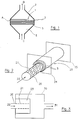
- FIG. 1 represents a structure made of adsorbent material consisting of layers which are substantially parallel to one another, superimposed and arranged in a treatment tank.
- This structure 1 consists either of a set of independent sheets mounted one by one in superposition, or of a single sheet of adsorbent material folded in an accordion (see FIGS. 5 and 6) so that a superposition is obtained. of several layers 3 of adsorbent material.
- the inter-layer spacing is a compromise between the flow of the system, the possible yawning of the fabrics and the induced turbulence.
- the thickness of each layer 3 also participates in the creation of inter-layer turbulence.
- the inter-layer space is between 5 and 10 mm approximately and preferably 5 mm approximately and the thickness of each layer is preferably between 2 and 3 mm.
- the structure 1 of adsorbent material is included in a treatment tank 2.
- the fluid to be treated penetrates into the treatment tank 2 through the inlet C and emerges free of the adsorbable constituents that it contained in D.
- the flow of fluid to be treated successively passes through the multiple layers 3 of adsorbent material and each layer 3 retains a portion of the adsorbable constituents.
- the geometry of the treatment tank 2 promotes the creation of inter-layer turbulence.
- the flow of fluid to be treated enters the treatment tank 2 through the inlet C, it undergoes a homogeneous depression favoring its distribution over the surface of the first layer 3 encountered, while creating turbulence in the zone E.
- the layers of adsorbent material advantageously consist of fabrics, membranes, fibers, fabrics, felts or foams, or any combination of at least two of these materials.
- the layers consist of adsorbent fabric.
- This fabric may consist of fibers, woven or not, of an adsorbent material.
- the adsorbent material used can be either natural (activated carbon) or compound.
- One of the compounds which is particularly suitable for the application carried out is polyacrylonitrile. This can be activated in order to increase its active surface.
- polyacrylonitrile provides an active surface of up to 1500 m2 / g of compound.
- the desorption operation consisting in heating the adsorbent material to desorb the adsorbed components is carried out by applying a potential difference between the ends A and B of the adsorbent structure.
- This potential difference between A and B generates a current flowing throughout the structure.
- the work of the inventors has shown that it is possible to use the electrical conductivity of activated carbon in the form of fabric to carry out desorption operations using the Joule effect. There is a sufficient conductivity (of course lower than that of graphite) probably due to the presence of oriented graphitic layers in the structure.
- the resistivity of the activated carbon thus allows it to heat up by the Joule effect and therefore the desorption of the adsorbed components. This desorption occurs for example around 300 ° C and constitutes the regeneration phase of the adsorbent material. More specifically, the desorption phenomenon can be controlled by modulating the difference in electrical potential across the structure, the temperature being a function of the power applied.
- the desorbed components can be recovered at the outlet of the tank, by a condensation operation, phase separation, or the like as explained below ...
- Desorption can be carried out under an initial partial vacuum capable of promoting transfer .
- the application of the potential difference can be done either at the two ends of the sheet of continuous activated carbon (folded in accordion), or at the ends of each set of continuous layer.
- the potential is applied to each thickness of fabric, the connections being able to be grouped (several fabrics) in series or in parallel.
- This difference in potential can also be applied to the ends of each layer when the structure 1 of adsorbent material consists of as many sheets as there are layers 3 of activated carbon.
- the adsorbent material used is not electrically conductive, desorption by the Joule effect is not possible. It is then possible, according to the invention, to use electrically conductive wires to which are attached the non-electrically conductive adsorbent particles. The application of a potential difference at the ends of such a wire causes it to heat up and the dissipated heat is transferred to said particles by conduction. this allows desorption of the adsorbed compounds.
- Such threads are woven to form a sheet (s) which can then be placed in a treatment tank 2 in accordance with FIG. 1.
- a flow of hot air is injected into the tank through the inlet C, and recovered at the outlet D of the tank.
- This air loaded with polluting particles can then undergo a treatment in order to separate the polluting particles from the air.
- any other fluid making it possible to perform the same function can be used (steam, water, neutral fluid, etc.).
- the desorbed molecules can also be removed by free convection.
- FIG. 2 represents a section of another embodiment of the present invention, in the form of a structure made up of layers of adsorbent material, superimposed, either concentric and of closed section, or wound in a spiral fashion.
- This figure shows a structure 23 of adsorbent material arranged around a tube 20 comprising multiple perforations 21.
- the structure 23 consists of layers 3 of concentric adsorbent material and of closed section superimposed on each other. These layers 3 of adsorbent material are spaced from each other by a certain distance.
- the fluid to be treated enters the tube 20 through the inlet 22 and can only exit from the tube 20 through the perforations 21, the tube 20 being blocked at its other end.
- the fluid to be treated then passes through the various layers 3 of adsorbent material which retain the adsorbable constituents.
- the inter-layer spacing promotes the creation of turbulence between the layers.
- each layer and its neighbor In order to maintain a space between each layer and its neighbor, it is necessary to ensure the holding in place of each layer. This can for example be achieved by placing the adsorbent layers between two end plates 24 and 25. These end plates 24, 25 can cooperate with spacers forming spacers, inserted between the adsorbent layers (not shown) making it possible to maintain a space between each layer and its neighbor or, more simply, exert a tensile force stiffening on the layers 3.
- the adsorbent material can, in this particular embodiment, also consist of fabrics, membranes, fibers, fabrics, felts or foams of electrically conductive material or not.
- the desorption operation consists, according to an advantageous embodiment of the present invention, in applying a potential difference between the two plates 24, 25, so as to cause heating of the adsorbent material by Joule effect.
- the adsorbent structure 23 is constituted by a winding of a single sheet of adsorbent material around the tube 20, while respecting an inter-layer space sufficient to promote the creation of turbulence, it is possible to perform the operation of desorption by the Joule effect by applying a potential difference between the tube 20 (conductor) and a conductive perforated plate (not shown) covering the entire structure 23.
- the adsorbed components are evacuated through the perforations in the conductive plate (not shown) by blowing a flow of air, water or steam into the tube 20.
- FIG. 3 represents a section of the device of FIG. 2 included in a treatment tank 30.
- the flow of fluid to be treated circulates in the tube 20 and escapes from this tube 20 through the orifices 21.
- the flow then crosses the various layers of the structure 23 of adsorbent material and the treated fluid leaves the tank of treatment 30.
- the adsorbable constituents are retained in the layers of the structure 23.
- the desorption operation consists in ceasing the introduction of the fluid to be treated 22 and in heating the adsorbent material by the Joule effect.
- the adsorbed constituents are then removed from the treatment tank 30 by blowing a neutral fluid (gas, water, etc.) into the tube 20 and recovered at the outlet 31 of the tank 30.
- a neutral fluid gas, water, etc.
- FIG. 4 A complete fluid treatment device according to the invention is shown in FIG. 4.
- This device comprises a tank 40 for symmetrical fluid treatment, the inlet and outlet of which are respectively denoted 41 and 42.
- the adsorbent structure present in the tank has a succession of layers 3 spaced apart.
- the fluid to be treated 43 is pumped by a supply pump 44 to a two-way valve 46.
- the two-way valve 46 makes it possible to select the fluid admitted to the inlet 21 of the treatment tank 40. This fluid is either the one to be treated 47 or the one 45 allowing the desorbed compounds to be removed from the treatment tank 40 .
- the valve 46 selects the fluid to be treated 47.
- the fluid 47 is introduced into the treatment tank 40 through the inlet 41 of frustoconical shape, in order to promote the creation of turbulence.
- the adsorbable constituents are retained by the layers 3 of adsorbent material and the regenerated fluid is evacuated from the tank 40 by the outlet 42.
- the three-way valve 48 allows the evacuation of the regenerated fluid 50, for example in the atmosphere if the fluid treated is air.
- the temperature of the adsorbent structure is either measured by thermocouples 52 and displayed 51, or determined from the applied voltage between A and B and adsorbed current.
- a stream of regeneration fluid 45 is injected into the treatment tank 40 to evacuate the adsorbed components from the tank 40.
- the valve 48 guides the flow of fluid present at the outlet 42 of the tank towards a treatment module 53 carrying out, for example, a cryoscopic trapping to separate the desorbed components from the regeneration fluid.
- the fluid freed from the desorbed components is then discharged 50, and the complete cycle can resume at its beginning.
- FIG. 5 represents an internal side view of the tank 40 of FIG. 4, containing a frame 50 making it possible to arrange the layers 3 of adsorbent material in the treatment tank 40.
- the structure 1 of adsorbent material advantageously consists of a sheet of adsorbent fabric.
- the latter is "folded in accordion" so that a certain number of layers 3 through which the fluid to be treated is obtained is obtained which is present at the inlet 41 of the treatment tank 40.
- the sheet of adsorbent fabric is stretched between the lower and upper walls of a frame 50 which can be removed from the treatment tank 40, by separation, by means of fastening means 52, of the frustoconical part 41 from the rest of the treatment tank 40.
- the frame 50 makes it possible to maintain the layers 3 of adsorbent material substantially parallel to one another, spaced apart by a distance d (between approximately 5 and approximately 10 mm) and perpendicular to the flow of fluid to be treated.
- the end of the first layer 51 of adsorbent material is connected to a terminal A to allow the application of the potential difference achieving the Joule effect.
- An insulating frame 53 constitutes the walls of the treatment tank and prevents heat loss.
- FIG. 6 represents a perspective view of the frame 50 of FIG. 5 introduced into the treatment tank 40.
- the arrows indicate the direction of folding adsorbent cloth.
- the use of reinforcements 50 having different distances d makes it possible to adapt the device of FIG. 4 to treatments of different fluids where, for example, the concentrations of adsorbable constituents are different, without having to change the whole device.
- An advantageous mode of use of the present invention consists in using two identical treatment tanks operating alternately, that is to say that one is in the adsorption phase while the other is in the desorption phase and vice versa. This configuration allows continuous fluid treatment.
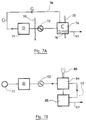
- FIGS. 7A, 7B illustrate two distinct preferential modes of treatment of the extracted gases produced during the regeneration phase by desorption of the components adsorbed in the reactors of the invention.
- the desorption gases are extracted from the reactors 71 by means of a carrier gas entrained in circulation by the extractor 72.
- the carrier gas is preferably air in an inert gas such than nitrogen.
- the gas stream is cooled 73 and introduced into a condensation chamber 74.
- the chamber 74 is at high partial pressure and maintained at low temperature, for example using a cooling fluid 75 (air, water, etc.).
- a cooling fluid 75 air, water, etc.
- the condensed compounds 76 are recovered at the bottom of the chamber 74, from which they can be drawn off 77.
- the carrier gas comprising the non-condensed extracted gaseous compounds is advantageously recycled 78 and returned to the reactor. In this way, the regeneration operation takes place away from any risk of pollution.
- a fan 81 conveys the gases extracted in the direction of a depletion installation 83.
- the installation 83 advantageously uses a depletion solvent, trickling for example by means of a transfer column on packing contained in an upper chamber 84.
- the loaded solution is received in a lower chamber 85, from which it can be sent 87 to be rectified, destroyed by incineration, or the like.
- the purified gas 86 is extracted at the top of the exhaustion chamber 84.
- the exhaustion installation 83 consists of a bio-purifier 84 cooperating with the separator 85.
- Biological purification can be carried out using hydrophilic bacteria either directly or by emulsion depending on whether the products to be extracted from the gases are water-soluble (butyl acetate, alcohols, phenols, ketones, etc.) or not. In the latter case, the emulsion can be produced for example using a venturi or a mixer.
- the charged gas can be sent directly to the burner or incinerator, particularly when the organic solvents to be removed have an advantageous PCI.
- FIGS. 1 to 7B represent only a few particular embodiments of the invention and the person skilled in the art will easily imagine other applications without going beyond the ambit of the present invention.
Landscapes
- Chemical & Material Sciences (AREA)
- Chemical Kinetics & Catalysis (AREA)
- Analytical Chemistry (AREA)
- Engineering & Computer Science (AREA)
- General Chemical & Material Sciences (AREA)
- Oil, Petroleum & Natural Gas (AREA)
- Toxicology (AREA)
- General Health & Medical Sciences (AREA)
- Electromagnetism (AREA)
- Organic Chemistry (AREA)
- Health & Medical Sciences (AREA)
- Physics & Mathematics (AREA)
- Separation Of Gases By Adsorption (AREA)
- Solid-Sorbent Or Filter-Aiding Compositions (AREA)
Priority Applications (2)
| Application Number | Priority Date | Filing Date | Title |
|---|---|---|---|
| EP19910460043 EP0532814B1 (de) | 1991-09-20 | 1991-09-20 | Vorrichtung zur Behandlung von Fluiden mit einer Adsorptionsstruktur aus geschichteten Lagen , die voneinander einen Abstand besitzen, und Regeneration durch den Jouleeffekt |
| DE1991626708 DE69126708T2 (de) | 1991-09-20 | 1991-09-20 | Vorrichtung zur Behandlung von Fluiden mit einer Adsorptionsstruktur aus geschichteten Lagen , die voneinander einen Abstand besitzen, und Regeneration durch den Jouleeffekt |
Applications Claiming Priority (1)
| Application Number | Priority Date | Filing Date | Title |
|---|---|---|---|
| EP19910460043 EP0532814B1 (de) | 1991-09-20 | 1991-09-20 | Vorrichtung zur Behandlung von Fluiden mit einer Adsorptionsstruktur aus geschichteten Lagen , die voneinander einen Abstand besitzen, und Regeneration durch den Jouleeffekt |
Publications (2)
| Publication Number | Publication Date |
|---|---|
| EP0532814A1 true EP0532814A1 (de) | 1993-03-24 |
| EP0532814B1 EP0532814B1 (de) | 1997-07-02 |
Family
ID=8208691
Family Applications (1)
| Application Number | Title | Priority Date | Filing Date |
|---|---|---|---|
| EP19910460043 Expired - Lifetime EP0532814B1 (de) | 1991-09-20 | 1991-09-20 | Vorrichtung zur Behandlung von Fluiden mit einer Adsorptionsstruktur aus geschichteten Lagen , die voneinander einen Abstand besitzen, und Regeneration durch den Jouleeffekt |
Country Status (2)
| Country | Link |
|---|---|
| EP (1) | EP0532814B1 (de) |
| DE (1) | DE69126708T2 (de) |
Cited By (6)
| Publication number | Priority date | Publication date | Assignee | Title |
|---|---|---|---|---|
| EP0684071A3 (de) * | 1994-05-26 | 1996-01-24 | Corning Inc | Elektrisch heitzbare Aktivkohlekörper für Adsorption und Desorptionsverwendungen. |
| FR2724326A1 (fr) * | 1994-09-14 | 1996-03-15 | Sartorius Gmbh | Unite de filtration pour la separation de substances avec des absorbants a membrane |
| EP0695210A4 (de) * | 1993-04-19 | 1996-05-01 | Envirosep Inc | Gleichgewichts-verfahren und -vorrichtung unter anwendung eines dicken films |
| US6107612A (en) * | 1998-01-26 | 2000-08-22 | Martinex R & D Inc. | Heating device and method |
| EP1170050A1 (de) | 2000-07-06 | 2002-01-09 | M+W Zander Facility Engineering GmbH | Verfahren zur Regenerierung von mit organischen Substanzen beladenen elektrisch leitfähigen Adsorbentien |
| JP2017205754A (ja) * | 2016-02-15 | 2017-11-24 | シリカ・フェアファーレンステヒニク・ゲゼルシャフト・ミト・ベシュレンクテル・ハフツング | 汚染物質で汚染されたガスを処理するための装置及び方法 |
Families Citing this family (4)
| Publication number | Priority date | Publication date | Assignee | Title |
|---|---|---|---|---|
| KR102267445B1 (ko) | 2016-02-15 | 2021-06-18 | 질리카 페어파렌스테크니크 게엠베하 | 오염물이 함유된 가스를 처리하기 위한 장치 및 방법 |
| DE202016000949U1 (de) | 2016-02-15 | 2016-03-17 | Silica Verfahrenstechnik Gmbh | Vorrichtung zum Behandeln eines mit Schadstoffen belasteten Gases |
| KR102124000B1 (ko) | 2018-11-12 | 2020-06-17 | 한국에너지기술연구원 | 모듈형으로 용량확장이 용이한 흡착모듈 유닛, 그 흡착모듈 유닛을 갖는 흡착 시스템 및 흡착 방법 |
| KR102158053B1 (ko) | 2018-11-12 | 2020-09-28 | 한국에너지기술연구원 | 활성탄소섬유를 이용한 흡착장치, 흡착시스템 및 흡착방법 |
Citations (6)
| Publication number | Priority date | Publication date | Assignee | Title |
|---|---|---|---|---|
| DE1769617A1 (de) * | 1968-06-18 | 1971-07-01 | Dow Chemical Co | Verfahren zur Desorption verdampfbarer Fluessigkeiten aus adsorbierenden Stoffen |
| DE1545233B2 (de) * | 1965-07-29 | 1971-07-29 | Black, Sivalls & Bryson Ine , Kan sas City, Mo (V St A ) | Verfahren und vorrichtung zum kontinuierlichen adsorbieren gasfoermiger kondensierbarer bestandteile.aus einem natur gasstrom |
| DE2807831A1 (de) * | 1977-02-24 | 1979-02-22 | Union Carbide Corp | Verfahren zum steuern der temperatur von fuellkoerperbetten |
| EP0104749A1 (de) * | 1982-08-27 | 1984-04-04 | Activated Carbon Services Limited | Vorrichtung zum Erhitzen eines festen Materials in Teilchenform |
| US4737164A (en) * | 1984-07-06 | 1988-04-12 | Seinajoen Kylmakone A ja T Saikkonen Ky | Process for recovering contaminants from gases |
| FR2612799A1 (fr) * | 1987-03-27 | 1988-09-30 | Ameg France | Procede et equipement de traitement et de recuperation de vapeurs de solvants par recyclage sur charbon actif |
-
1991
- 1991-09-20 DE DE1991626708 patent/DE69126708T2/de not_active Expired - Fee Related
- 1991-09-20 EP EP19910460043 patent/EP0532814B1/de not_active Expired - Lifetime
Patent Citations (6)
| Publication number | Priority date | Publication date | Assignee | Title |
|---|---|---|---|---|
| DE1545233B2 (de) * | 1965-07-29 | 1971-07-29 | Black, Sivalls & Bryson Ine , Kan sas City, Mo (V St A ) | Verfahren und vorrichtung zum kontinuierlichen adsorbieren gasfoermiger kondensierbarer bestandteile.aus einem natur gasstrom |
| DE1769617A1 (de) * | 1968-06-18 | 1971-07-01 | Dow Chemical Co | Verfahren zur Desorption verdampfbarer Fluessigkeiten aus adsorbierenden Stoffen |
| DE2807831A1 (de) * | 1977-02-24 | 1979-02-22 | Union Carbide Corp | Verfahren zum steuern der temperatur von fuellkoerperbetten |
| EP0104749A1 (de) * | 1982-08-27 | 1984-04-04 | Activated Carbon Services Limited | Vorrichtung zum Erhitzen eines festen Materials in Teilchenform |
| US4737164A (en) * | 1984-07-06 | 1988-04-12 | Seinajoen Kylmakone A ja T Saikkonen Ky | Process for recovering contaminants from gases |
| FR2612799A1 (fr) * | 1987-03-27 | 1988-09-30 | Ameg France | Procede et equipement de traitement et de recuperation de vapeurs de solvants par recyclage sur charbon actif |
Cited By (8)
| Publication number | Priority date | Publication date | Assignee | Title |
|---|---|---|---|---|
| EP0695210A4 (de) * | 1993-04-19 | 1996-05-01 | Envirosep Inc | Gleichgewichts-verfahren und -vorrichtung unter anwendung eines dicken films |
| EP0684071A3 (de) * | 1994-05-26 | 1996-01-24 | Corning Inc | Elektrisch heitzbare Aktivkohlekörper für Adsorption und Desorptionsverwendungen. |
| FR2724326A1 (fr) * | 1994-09-14 | 1996-03-15 | Sartorius Gmbh | Unite de filtration pour la separation de substances avec des absorbants a membrane |
| GB2293119A (en) * | 1994-09-14 | 1996-03-20 | Sartorius Gmbh | Membrane filtration unit |
| GB2293119B (en) * | 1994-09-14 | 1998-06-24 | Sartorius Gmbh | Filtration unit |
| US6107612A (en) * | 1998-01-26 | 2000-08-22 | Martinex R & D Inc. | Heating device and method |
| EP1170050A1 (de) | 2000-07-06 | 2002-01-09 | M+W Zander Facility Engineering GmbH | Verfahren zur Regenerierung von mit organischen Substanzen beladenen elektrisch leitfähigen Adsorbentien |
| JP2017205754A (ja) * | 2016-02-15 | 2017-11-24 | シリカ・フェアファーレンステヒニク・ゲゼルシャフト・ミト・ベシュレンクテル・ハフツング | 汚染物質で汚染されたガスを処理するための装置及び方法 |
Also Published As
| Publication number | Publication date |
|---|---|
| EP0532814B1 (de) | 1997-07-02 |
| DE69126708D1 (de) | 1997-08-07 |
| DE69126708T2 (de) | 1998-02-19 |
Similar Documents
| Publication | Publication Date | Title |
|---|---|---|
| FR2659869A1 (fr) | Dispositif de traitement de fluide, au moyen d'une structure d'adsorption a couches superposees espacees, et regeneration par effet joule. | |
| EP0532814B1 (de) | Vorrichtung zur Behandlung von Fluiden mit einer Adsorptionsstruktur aus geschichteten Lagen , die voneinander einen Abstand besitzen, und Regeneration durch den Jouleeffekt | |
| EP3043884B1 (de) | Regenerierungsverfahren zur beseitigung von siloxanverbindungen aus biogas | |
| US5087374A (en) | Removal of contaminates from granular solids | |
| EP0655418B1 (de) | Unterwassermembranfilteranlage zur Trinkwasserbereitung | |
| EP0284068A1 (de) | Verfahren und Ausrüstung für die Behandlung und Wiedergewinnung von Lösungsmitteldämpfen durch Recycling der Aktivkohle | |
| JP7045134B2 (ja) | 汚染物質で汚染されたガスを処理するための装置及び方法 | |
| FR2820056A1 (fr) | Appareil de filtrage, procede associe de contre-lavage, dispositif de filtrage et centrale electrique | |
| FR2711650A1 (fr) | Procédé de purification d'une solution glycolique à base d'un ou plusieurs glycols et renfermant, en outre, de l'eau et, à titre d'impuretés, des sels et des hydrocarbures. | |
| FR2508340A1 (fr) | Purification de gaz contenant des impuretes solides et gazeuses | |
| FR2738501A1 (fr) | Procede et dispositif pour epurer des veines d'effluents gazeux chargees de substances polluantes | |
| JP2017205754A5 (de) | ||
| KR102492039B1 (ko) | 수처리용 활성탄 필터모듈과 그 재생방법 및 활성탄을 이용한 영가철-활성탄 복합체 필터모듈과 그 재생방법 | |
| EP1361916A2 (de) | Selektive, wasserstoffdurchlässige membranverbundstrukturen und brenngasprozessor unter verwendung derselben | |
| KR20020003518A (ko) | 유기물질로 부하된 도전성 흡착체의 재생방법 | |
| FR2754736A1 (fr) | Procede de regeneration d'un compose liquide de la famille des glycols, utilise dans la deshydratation d'un gaz | |
| FR2827189A1 (fr) | Procede et dispositif pour capter les vapeurs contenues dans un effluent gazeux | |
| JP2004000916A (ja) | 分解対象物質装置及びその分解方法 | |
| EP0568747A1 (de) | Verfahren zur Behandlung von verunreinigten Gasen durch zumindest ein Sorptionsmittel und Vorrichtung zur Durchführung dieses Verfahrens | |
| EP4547780A1 (de) | Verfahren zur umwandlung von kohlendioxid unter erzeugung von wasserstoff und/oder methan | |
| FR2832078A1 (fr) | Filtre a charbons actifs de purification de gaz, comprenant une desorption par chauffage a induction | |
| FR2687660A1 (fr) | Procede et dispositif de demineralisation de l'eau. | |
| FR2921055A1 (fr) | Reacteur de reduction du dioxyde de carbone par une action conjuguee d'electrolyse et d'un plasma | |
| RU2060787C1 (ru) | Фильтр | |
| EP4149672B1 (de) | Filterelement für gasförmige fluide |
Legal Events
| Date | Code | Title | Description |
|---|---|---|---|
| PUAI | Public reference made under article 153(3) epc to a published international application that has entered the european phase |
Free format text: ORIGINAL CODE: 0009012 |
|
| 111L | Licence recorded |
Free format text: 0100 SOCREMATIC S.A. |
|
| AK | Designated contracting states |
Kind code of ref document: A1 Designated state(s): BE DE FR GB IT NL |
|
| 17P | Request for examination filed |
Effective date: 19930403 |
|
| 17Q | First examination report despatched |
Effective date: 19931229 |
|
| GRAG | Despatch of communication of intention to grant |
Free format text: ORIGINAL CODE: EPIDOS AGRA |
|
| GRAH | Despatch of communication of intention to grant a patent |
Free format text: ORIGINAL CODE: EPIDOS IGRA |
|
| GRAH | Despatch of communication of intention to grant a patent |
Free format text: ORIGINAL CODE: EPIDOS IGRA |
|
| RTI1 | Title (correction) | ||
| GRAA | (expected) grant |
Free format text: ORIGINAL CODE: 0009210 |
|
| AK | Designated contracting states |
Kind code of ref document: B1 Designated state(s): BE DE FR GB IT NL |
|
| REF | Corresponds to: |
Ref document number: 69126708 Country of ref document: DE Date of ref document: 19970807 |
|
| ITF | It: translation for a ep patent filed | ||
| GBT | Gb: translation of ep patent filed (gb section 77(6)(a)/1977) |
Effective date: 19971001 |
|
| PLBE | No opposition filed within time limit |
Free format text: ORIGINAL CODE: 0009261 |
|
| STAA | Information on the status of an ep patent application or granted ep patent |
Free format text: STATUS: NO OPPOSITION FILED WITHIN TIME LIMIT |
|
| 26N | No opposition filed | ||
| PGFP | Annual fee paid to national office [announced via postgrant information from national office to epo] |
Ref country code: BE Payment date: 20000908 Year of fee payment: 10 |
|
| PGFP | Annual fee paid to national office [announced via postgrant information from national office to epo] |
Ref country code: GB Payment date: 20000918 Year of fee payment: 10 |
|
| PGFP | Annual fee paid to national office [announced via postgrant information from national office to epo] |
Ref country code: DE Payment date: 20000928 Year of fee payment: 10 |
|
| PGFP | Annual fee paid to national office [announced via postgrant information from national office to epo] |
Ref country code: NL Payment date: 20000930 Year of fee payment: 10 |
|
| PG25 | Lapsed in a contracting state [announced via postgrant information from national office to epo] |
Ref country code: GB Free format text: LAPSE BECAUSE OF NON-PAYMENT OF DUE FEES Effective date: 20010920 |
|
| PGFP | Annual fee paid to national office [announced via postgrant information from national office to epo] |
Ref country code: FR Payment date: 20010928 Year of fee payment: 11 |
|
| PG25 | Lapsed in a contracting state [announced via postgrant information from national office to epo] |
Ref country code: BE Free format text: LAPSE BECAUSE OF NON-PAYMENT OF DUE FEES Effective date: 20010930 |
|
| REG | Reference to a national code |
Ref country code: GB Ref legal event code: IF02 |
|
| BERE | Be: lapsed |
Owner name: LE CLOIREC PIERRE Effective date: 20010930 Owner name: BAUDU MICHEL Effective date: 20010930 Owner name: MARTIN GUY Effective date: 20010930 |
|
| PG25 | Lapsed in a contracting state [announced via postgrant information from national office to epo] |
Ref country code: NL Free format text: LAPSE BECAUSE OF NON-PAYMENT OF DUE FEES Effective date: 20020401 |
|
| PG25 | Lapsed in a contracting state [announced via postgrant information from national office to epo] |
Ref country code: DE Free format text: LAPSE BECAUSE OF NON-PAYMENT OF DUE FEES Effective date: 20020501 |
|
| GBPC | Gb: european patent ceased through non-payment of renewal fee |
Effective date: 20010920 |
|
| NLV4 | Nl: lapsed or anulled due to non-payment of the annual fee |
Effective date: 20020401 |
|
| NLV4 | Nl: lapsed or anulled due to non-payment of the annual fee |
Effective date: 20020401 |
|
| PG25 | Lapsed in a contracting state [announced via postgrant information from national office to epo] |
Ref country code: FR Free format text: LAPSE BECAUSE OF NON-PAYMENT OF DUE FEES Effective date: 20030603 |
|
| REG | Reference to a national code |
Ref country code: FR Ref legal event code: ST |
|
| PG25 | Lapsed in a contracting state [announced via postgrant information from national office to epo] |
Ref country code: IT Free format text: LAPSE BECAUSE OF NON-PAYMENT OF DUE FEES Effective date: 20050920 |