EP0532924B1 - Dispositif de changement de vitesses pour une boîte de vitesses d'une véhicule automobile - Google Patents
Dispositif de changement de vitesses pour une boîte de vitesses d'une véhicule automobile Download PDFInfo
- Publication number
- EP0532924B1 EP0532924B1 EP92114170A EP92114170A EP0532924B1 EP 0532924 B1 EP0532924 B1 EP 0532924B1 EP 92114170 A EP92114170 A EP 92114170A EP 92114170 A EP92114170 A EP 92114170A EP 0532924 B1 EP0532924 B1 EP 0532924B1
- Authority
- EP
- European Patent Office
- Prior art keywords
- gear
- shift
- synchronized
- change transmission
- transmission according
- Prior art date
- Legal status (The legal status is an assumption and is not a legal conclusion. Google has not performed a legal analysis and makes no representation as to the accuracy of the status listed.)
- Expired - Lifetime
Links
Images



Classifications
-
- F—MECHANICAL ENGINEERING; LIGHTING; HEATING; WEAPONS; BLASTING
- F16—ENGINEERING ELEMENTS AND UNITS; GENERAL MEASURES FOR PRODUCING AND MAINTAINING EFFECTIVE FUNCTIONING OF MACHINES OR INSTALLATIONS; THERMAL INSULATION IN GENERAL
- F16H—GEARING
- F16H63/00—Control outputs from the control unit to change-speed- or reversing-gearings for conveying rotary motion or to other devices than the final output mechanism
- F16H63/02—Final output mechanisms therefor; Actuating means for the final output mechanisms
- F16H63/08—Multiple final output mechanisms being moved by a single common final actuating mechanism
- F16H63/20—Multiple final output mechanisms being moved by a single common final actuating mechanism with preselection and subsequent movement of each final output mechanism by movement of the final actuating mechanism in two different ways, e.g. guided by a shift gate
-
- F—MECHANICAL ENGINEERING; LIGHTING; HEATING; WEAPONS; BLASTING
- F16—ENGINEERING ELEMENTS AND UNITS; GENERAL MEASURES FOR PRODUCING AND MAINTAINING EFFECTIVE FUNCTIONING OF MACHINES OR INSTALLATIONS; THERMAL INSULATION IN GENERAL
- F16H—GEARING
- F16H63/00—Control outputs from the control unit to change-speed- or reversing-gearings for conveying rotary motion or to other devices than the final output mechanism
- F16H63/02—Final output mechanisms therefor; Actuating means for the final output mechanisms
- F16H63/30—Constructional features of the final output mechanisms
- F16H63/32—Gear shift yokes, e.g. shift forks
-
- F—MECHANICAL ENGINEERING; LIGHTING; HEATING; WEAPONS; BLASTING
- F16—ENGINEERING ELEMENTS AND UNITS; GENERAL MEASURES FOR PRODUCING AND MAINTAINING EFFECTIVE FUNCTIONING OF MACHINES OR INSTALLATIONS; THERMAL INSULATION IN GENERAL
- F16H—GEARING
- F16H63/00—Control outputs from the control unit to change-speed- or reversing-gearings for conveying rotary motion or to other devices than the final output mechanism
- F16H63/02—Final output mechanisms therefor; Actuating means for the final output mechanisms
- F16H63/30—Constructional features of the final output mechanisms
- F16H63/32—Gear shift yokes, e.g. shift forks
- F16H2063/325—Rocker or swiveling forks, i.e. the forks are pivoted in the gear case when moving the sleeve
-
- F—MECHANICAL ENGINEERING; LIGHTING; HEATING; WEAPONS; BLASTING
- F16—ENGINEERING ELEMENTS AND UNITS; GENERAL MEASURES FOR PRODUCING AND MAINTAINING EFFECTIVE FUNCTIONING OF MACHINES OR INSTALLATIONS; THERMAL INSULATION IN GENERAL
- F16H—GEARING
- F16H63/00—Control outputs from the control unit to change-speed- or reversing-gearings for conveying rotary motion or to other devices than the final output mechanism
- F16H63/02—Final output mechanisms therefor; Actuating means for the final output mechanisms
- F16H63/30—Constructional features of the final output mechanisms
- F16H63/3069—Interrelationship between two or more final output mechanisms
-
- Y—GENERAL TAGGING OF NEW TECHNOLOGICAL DEVELOPMENTS; GENERAL TAGGING OF CROSS-SECTIONAL TECHNOLOGIES SPANNING OVER SEVERAL SECTIONS OF THE IPC; TECHNICAL SUBJECTS COVERED BY FORMER USPC CROSS-REFERENCE ART COLLECTIONS [XRACs] AND DIGESTS
- Y10—TECHNICAL SUBJECTS COVERED BY FORMER USPC
- Y10T—TECHNICAL SUBJECTS COVERED BY FORMER US CLASSIFICATION
- Y10T74/00—Machine element or mechanism
- Y10T74/20—Control lever and linkage systems
- Y10T74/20012—Multiple controlled elements
- Y10T74/20018—Transmission control
- Y10T74/20085—Restriction of shift, gear selection, or gear engagement
- Y10T74/20104—Shift element interlock
Definitions
- the invention relates to a synchronized speed change transmission of a motor vehicle with a switching device according to the preamble of claim 1.
- Such a speed change transmission is known from DE-A-14 80 679.
- a gearshift shaft which is mounted in the gearbox housing for longitudinal and rotary movement, engages in one of three gearshift levers.
- the gearshift levers are connected to two vibrating forks mounted in the gearbox housing parallel to the gearshift shaft by means of two push rods articulated on them.
- a third tuning fork is directly connected to the gear lever located directly above it.
- a speed change transmission is known in which three synchronizing clutches are guided on a transmission shaft and can be displaced by vibrating forks. Each of these tuning forks is connected to a push rod which is guided in the transmission housing in a longitudinally movable manner. These three push rods have mutually aligned grooves in which the shift finger of a shift shaft engages.
- a shift finger of the shift shaft interacts directly with shift straps which are attached to tuning forks and are longitudinally guided on a guide rail of a shift rod; further intermediate gear parts are unnecessary.
- the selector rod is mounted in the gearbox housing perpendicular to the selector shaft.
- the shift fork for the reverse gear is attached at the end to this shift rod.
- the tuning fork of the G5 / G6 transmission gears is replaced by a shift fork that is rotatably and longitudinally displaceable on the shift rod.
- a normal 6-speed gearbox or a gearbox with overdrive can be implemented at extremely low conversion costs.
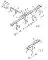
- a selector shaft 1 is longitudinally displaceable and rotatable; it can be operated from the outside with a lever 2.
- a shift finger 3 fastened to the shift shaft 1 can be inserted into the mutually aligned grooves 4 of three shift tabs 5, 6, 7 which are guided parallel to one another.
- the shift tabs 5 and 7 are articulated to vibrating forks 8 and 10, which are mounted in the transmission housing and shift the gears G5 and G6, and G2 and G1 by pivoting.
- a guide rail 12 attached to a shift rod 11 serves for the longitudinal guidance of the shift straps 5, 7.
- the shift straps 5 and 7 of the gears G6 and G5 or G2 and G1 are longitudinally guided on the middle shift strap 6 of the gears G4 / G3.
- a shift fork 13 for the reverse gear R is attached at one end of the shift rod 11.
- the tuning fork 8 is arranged near the other end of the shift rod 11 and, in the overdrive version, is replaced by a shift fork 15 mounted on the shift rod 11 and actuated by a shift plate 14.
- a gear shift for an overdrive transmission is implemented in FIG. 3 on a 6-speed transmission. All gear ratios go a bit at Overdrive faster than with the normal version.
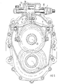
- a gear housing 16 is flanged to a clutch bell 17 of the engine.
- a gear wheel 20 for the fifth gear G5 is fixedly mounted on the drive shaft 19 coming from the motor and mounted in the gear housing 16 with a tapered roller bearing 18. It meshes continuously with a fixed gear 21 of a countershaft 22 parallel to the drive shaft 19.
- the fixed gears of the 6th gear G6, the 4th gear G4, the 3rd gear G3, the 2nd gear G2, the 1st gear G1 and the reverse gear R arranged.
- the associated idler gears of these gears are mounted on an output shaft 23 coaxial with the drive shaft 19 and mounted in it.
- the gears G5 / G6, G4 / G3 and G2 / G1 can be shifted by synchronizing clutches 24 between them, shifting forks or vibrating forks engaging in the shift sleeves 25 of the synchronizing clutches 24 in a form-fitting manner.
- the countershaft 22 is driven continuously via the gear pair 20, 21.
- the output shaft 23 is also rotated and, depending on the gear selected, rotates at the corresponding speed.
- shifting the fifth gear G5 the output shaft 23 runs at the same speed as the drive shaft 19.
- the gears G5 / G6 are shifted with a tuning fork 8 in the normal version of the transmission, with a shift fork 15 in the overdrive version, the fifth gear is shifted by moving the shift plate to the left and the sixth gear by moving the shift gate to the right without that the gearshift device must be changed further. Only the wheel sets for G5 / G6 are to be exchanged; a shift fork 15 is to be used instead of the tuning fork 8.
- the shift fork 15 is supported in needle bearings 26 on the shift rod 11.
- the tuning fork 8 like all other tuning forks, is pivotably mounted on two coaxial pins 27 in the gear housing 16.
- a shift tab 5 hinged to it is guided longitudinally on a guide rail 12 of the shift rod 11 and in a groove 28 of the central shift tab 6 of the gears G4 / G3.
- the shift tab 7 of the gears G2 / G1 is longitudinally guided.
- the shift fork 13 for reverse gear R is pinned to the shift rod 11.
- the shift finger 3 is pushed into the groove 4 of the shift rod 11.
- the shift rod 11 is then shifted longitudinally and the reverse gear R is shifted.
- the shift rod 11 is mounted on both sides in the gear housing 16 in slide bearings 30. Their longitudinal position is detected by a sensor 31.
- the shift shaft 1, which is perpendicular to the shift rod 11, is mounted in the gear housing 16 on both sides in needle bearings 32. Their three rotational positions can be locked by engaging a spring pin 36 in a locking profile of the control shaft 1.
- a locking bracket 33 is provided in order to avoid that an adjacent gear is simultaneously shifted when shifting a gear.
- the locking bracket 33 bears on both end faces on the hub 34 of the shift finger 3. He takes part in the longitudinal movements of the shift finger 3 and engages positively in the shift tabs of the transmission gears that are not to be shifted. The swing forks of these gears are secured against twisting.
- the shift finger 3 passes through the locking bracket 33. In a slot 4 of the locking bracket 33, it can be freely rotated to shift the selected gear.
- the locking bracket 33 is guided in the longitudinal direction and secured against rotation in a longitudinal groove 35 of the transmission housing 16 which runs parallel to the selector shaft 1.
Landscapes
- Engineering & Computer Science (AREA)
- General Engineering & Computer Science (AREA)
- Mechanical Engineering (AREA)
- Gear-Shifting Mechanisms (AREA)
Claims (8)
- Dispositif de changement de vitesses synchronisé pour un véhicule automobile, avec un dispositif de manoeuvre, quelques rapport de vitesse en marche avant pouvant être enclenchés à l'aide de fourchettes oscillantes, s'engageant dans des couplages de synchronisation, pouvant pivoter dans le carter de boîtier de vitesse, et un arbre de manoeuvre étant monté dans le carter de boîte de vitesse, de façon à pouvoir se déplacer parallèlement par rapport à l'axe de tourillonnement des fourchettes oscillantes et à pouvoir tourner, caractérisé en ce que, sur l'arbre de manoeuvre (1) est fixé un doigt de manoeuvre (3), coopérant avec des pattes de manoeuvre (5, 6, 7) fixées sur les fourchettes oscillantes (8, 9, 10), de manière qu'au moyen de son déplacement longitudinal dans les rainures (4) alignées vis à vis de lui, des pattes de manoeuvre (5, 6, 7), les rapport de vitesse puissent être présélectionnés et puissent être enclenchés, par rotation du doigt de manoeuvre (3), et en ce que les pattes de manoeuvre sont guidées longitudinalement sur une glissière de guidage (12) de la tige de manoeuvre (11).
- Dispositif de changement de vitesses synchronisé selon la revendication 1, caractérisé en ce qu'au moins trois pattes de manoeuvre (5, 6, 7) sont prévues et en ce que les autres pattes de manoeuvre (5, 7) sont guidées longitudinalement sur une patte de manoeuvre (6) médiane.
- Dispositif de changement de vitesses synchronisé selon la revendication 1, caractérisé en ce que, lorsque la boîte de vitesse est conçue avec une surmultipliée, la fourchette oscillante (8) du plus haut rapport de vitesse est remplacée par une fourchette de manoeuvre (15), déplaçable longitudinalement et pouvant tourner sur la tige de manoeuvre (11).
- Dispositif de changement de vitesses synchronisé selon la revendication 1, caractérisé en ce que la marche arrière (R) peut être actionnée à l'aide d'une fourchette de manoeuvre (13), fixée coté extrémité sur la tige de manoeuvre (11).
- Dispositif de changement de vitesses synchronisé selon la revendication 1, caractérisé en ce que la glissière de guidage (12) est réalisée d'un seul tenant, par forgeage, sur la tige de manoeuvre (11).
- Dispositif de changement de vitesses synchronisé selon la revendication 1, caractérisé en ce que les pattes de manoeuvre sont articulées sur les fourchettes oscillantes (8, 10).
- Dispositif de changement de vitesses synchronisé selon la revendication 1, caractérisé en ce que le doigt de manoeuvre (3) est entouré par un étrier de blocage (33) et le traverse, l'étrier de blocage (33) étant guidé de façon à pouvoir se déplacer longitudinalement dans la direction axiale de l'arbre de manoeuvre (1), en étant bloqué en rotation, et en appuyant sur un moyeu (34) guidant sur les deux faces frontales l'un des doigts de manoeuvre (3).
- Dispositif de changement de vitesses synchronisé selon la revendication 1, caractérisé en ce que l'étrier de blocage (33) est guidé longitudinalement dans une rainure longitudinale (33) du carter de boîte de vitesse (16) et est bloqué en rotation.
Applications Claiming Priority (2)
| Application Number | Priority Date | Filing Date | Title |
|---|---|---|---|
| DE4131162 | 1991-09-19 | ||
| DE4131162A DE4131162A1 (de) | 1991-09-19 | 1991-09-19 | Schaltvorrichtung fuer ein geschwindigkeitswechselgetriebe eines kraftfahrzeuges |
Publications (3)
| Publication Number | Publication Date |
|---|---|
| EP0532924A2 EP0532924A2 (fr) | 1993-03-24 |
| EP0532924A3 EP0532924A3 (en) | 1994-05-18 |
| EP0532924B1 true EP0532924B1 (fr) | 1995-10-11 |
Family
ID=6440961
Family Applications (1)
| Application Number | Title | Priority Date | Filing Date |
|---|---|---|---|
| EP92114170A Expired - Lifetime EP0532924B1 (fr) | 1991-09-19 | 1992-08-20 | Dispositif de changement de vitesses pour une boîte de vitesses d'une véhicule automobile |
Country Status (4)
| Country | Link |
|---|---|
| US (1) | US5309785A (fr) |
| EP (1) | EP0532924B1 (fr) |
| JP (1) | JPH05280638A (fr) |
| DE (2) | DE4131162A1 (fr) |
Families Citing this family (36)
| Publication number | Priority date | Publication date | Assignee | Title |
|---|---|---|---|---|
| US5740695A (en) * | 1996-01-29 | 1998-04-21 | Ford Global Technologies, Inc. | Shift device for a manual transmission |
| DE19609209C2 (de) * | 1996-03-09 | 1998-12-10 | Daimler Benz Ag | Schaltvorrichtung für ein Zahnräderwechselgetriebe |
| DE19610104C2 (de) * | 1996-03-15 | 1999-07-01 | Daimler Chrysler Ag | Schaltvorrichtung für ein Zahnräderwechselgetriebe sowie Verfahren zum Steuern dafür |
| US5832777A (en) * | 1996-11-19 | 1998-11-10 | Borg-Warner Automotive, Inc. | Electromechanical transmission control apparatus |
| EP0859173B1 (fr) * | 1997-02-17 | 2002-03-20 | Robert Bosch Gmbh | Dispositif de commande d'une boíte de vitesses multiples pour véhicule automobile |
| DE19742065C1 (de) * | 1997-09-24 | 1998-12-24 | Daimler Benz Ag | Schaltvorrichtung für ein Zahnräderwechselgetriebe |
| DE19753728A1 (de) | 1997-12-04 | 1999-06-10 | Zahnradfabrik Friedrichshafen | 12-Gang-Getriebe für Nutzfahrzeuge |
| US5996436A (en) * | 1998-02-04 | 1999-12-07 | Zf Friedrichshafen Ag | Single-shaft operating device for actuating a shift mechanism including shift interlock means |
| DE29814943U1 (de) * | 1998-02-13 | 1999-05-27 | Kochendörfer & Kiep Stanz- und Feinstanzwerk GmbH & Co. KG, 78467 Konstanz | Getriebe |
| DE19816385A1 (de) * | 1998-04-11 | 1999-10-14 | Zahnradfabrik Friedrichshafen | Schalteinrichtung für Zahnräder-Wechselgetriebe |
| US6082215A (en) * | 1998-08-28 | 2000-07-04 | Zf Meritor | Single rail top cover assembly |
| DE19949230B4 (de) * | 1999-10-13 | 2010-04-29 | Zf Friedrichshafen Ag | 12-Gang-Getriebe |
| DE19951683A1 (de) * | 1999-10-27 | 2001-05-03 | Zahnradfabrik Friedrichshafen | Einstangen-Schalteinrichtung für Kraftfahrzeug-Handschaltgetriebe |
| DE10018850A1 (de) | 2000-04-14 | 2001-10-18 | Schaeffler Waelzlager Ohg | Schaltgabel für ein Zahnräderwechselgetriebe |
| DE10032163A1 (de) | 2000-07-01 | 2002-01-10 | Schaeffler Waelzlager Ohg | Betätigungsvorrichtung für ein Zahnräderwechselgetriebe |
| DE10125098B4 (de) * | 2001-05-23 | 2016-03-17 | Schaeffler Technologies AG & Co. KG | Schaltgabel für ein Wechselgetriebe mit einem gabelförmig ausgebildeten Grundkörper aus Blech |
| EP1310707B1 (fr) | 2001-11-10 | 2004-03-17 | GETRAG FORD Transmissions GmbH | Dispositif de changement de vitesses et méthode de mouvement et guidage de fourchettes dans une transmission à changement de vitesses |
| DE10206470A1 (de) * | 2002-02-16 | 2003-08-28 | Bayerische Motoren Werke Ag | Schaltgetriebe |
| DE10212245A1 (de) * | 2002-03-19 | 2003-10-16 | Ise Ind Gmbh | Schaltgabel für Getriebe, insbesondere Kfz-Getriebe und Herstellungsverfahren für eine Schaltgabel |
| DE102005005693A1 (de) * | 2005-02-08 | 2006-08-17 | Fzgmbh | Schaltvorrichtung |
| DE602006000491T2 (de) * | 2006-03-06 | 2009-01-22 | C.R.F. S.C.P.A. | Getriebeschaltgabel |
| FR2923885B1 (fr) * | 2007-11-20 | 2010-04-02 | Peugeot Citroen Automobiles Sa | Dispositif de commande interne d'une boite de vitesses de vehicule automobile. |
| DE102008029262B4 (de) * | 2008-06-19 | 2020-03-26 | Schaeffler Technologies AG & Co. KG | Verriegelungsvorrichtung zur Verriegelung von Schaltschienen eines Getriebes |
| CN101749420B (zh) * | 2008-12-19 | 2014-11-12 | 卡特彼勒(青州)有限公司 | 车辆变速器的档位控制方法及相应液压操纵系统 |
| DE102010001295A1 (de) * | 2010-01-28 | 2011-08-18 | ZF Friedrichshafen AG, 88046 | Schaltsicherungsvorrichtung eines mehrstufigen Schaltgetriebes |
| CN102777595A (zh) * | 2012-08-20 | 2012-11-14 | 中国重汽集团济南动力有限公司 | 同步器变速器用选换挡机构总成 |
| CN102853071B (zh) * | 2012-09-21 | 2015-04-22 | 长城汽车股份有限公司 | 一种变速器换挡机构、变速器及机动车辆 |
| KR101637693B1 (ko) * | 2014-10-15 | 2016-07-08 | 현대자동차주식회사 | 수동변속기용 변속 장치 |
| JP6547390B2 (ja) * | 2015-04-23 | 2019-07-24 | アイシン・エィ・ダブリュ株式会社 | 変速機 |
| CN105840816B (zh) * | 2016-05-05 | 2018-05-22 | 中国第一汽车股份有限公司 | 一种带同步器的双离合器自动变速器挂挡控制方法 |
| DE102016214864A1 (de) * | 2016-08-10 | 2018-02-15 | Zf Friedrichshafen Ag | Schaltvorrichtung zum manuellen Schalten eines mehrstufigen Getriebes |
| CN108869733B (zh) * | 2017-05-12 | 2021-08-03 | 舍弗勒技术股份两合公司 | 倒档用的输入轴制动系统和方法 |
| CN108930788A (zh) * | 2018-08-30 | 2018-12-04 | 安徽江淮汽车集团股份有限公司 | 一种变速器拨叉结构 |
| DE102019126659A1 (de) * | 2019-10-02 | 2021-04-08 | Wabco Europe Bvba | Schaltvorrichtung eines Schaltgetriebes |
| CN113586716B (zh) * | 2021-07-05 | 2023-03-24 | 浙江万里扬股份有限公司 | 换挡机构和车辆 |
| FR3143084A1 (fr) * | 2022-12-13 | 2024-06-14 | Renault S.A.S | Arbre agencé au sein d’un alésage non débouchant comprenant un moyen de dégazage d’un tel alésage. |
Family Cites Families (10)
| Publication number | Priority date | Publication date | Assignee | Title |
|---|---|---|---|---|
| US3242759A (en) * | 1963-06-28 | 1966-03-29 | Zahnradfabrik Friedrichshafen | Shifting arrangement for change speed gears of motor vehicles |
| DE2750275C2 (de) * | 1977-11-10 | 1982-04-01 | Getrag Getriebe- Und Zahnradfabrik Gmbh, 7140 Ludwigsburg | Schalteinrichtung für mehrgängige Wechselgetriebe |
| GB2026109B (en) * | 1978-07-25 | 1983-03-02 | Dana Corp | Gear selector mechanisms |
| US4432251A (en) * | 1981-01-29 | 1984-02-21 | Clark Equipment Company | Lost motion transmission control cams |
| US4543846A (en) * | 1981-08-20 | 1985-10-01 | Toyota Jidosha Kabushiki Kaisha | Interlocking construction in transmission manipulation device for manual transmission |
| JPS5836426U (ja) * | 1981-09-04 | 1983-03-09 | トヨタ自動車株式会社 | 手動歯車変速機の変速操作機構 |
| JPS59127930U (ja) * | 1983-02-17 | 1984-08-28 | トヨタ自動車株式会社 | 車両用変速機の同期装置 |
| US4532823A (en) * | 1983-10-06 | 1985-08-06 | Chrysler Corporation | Concentric shift rail mechanism |
| WO1986003858A1 (fr) * | 1984-12-22 | 1986-07-03 | Zahnradfabrik Friedrichshafen Ag | Dispositif de changement de vitesse |
| DE3841780A1 (de) * | 1988-12-12 | 1990-08-23 | Porsche Ag | Betaetigungsvorrichtung fuer ein gangschaltgetriebe |
-
1991
- 1991-09-19 DE DE4131162A patent/DE4131162A1/de not_active Withdrawn
-
1992
- 1992-08-20 DE DE59203980T patent/DE59203980D1/de not_active Expired - Fee Related
- 1992-08-20 EP EP92114170A patent/EP0532924B1/fr not_active Expired - Lifetime
- 1992-09-18 JP JP4249970A patent/JPH05280638A/ja not_active Withdrawn
- 1992-09-21 US US07/947,481 patent/US5309785A/en not_active Expired - Fee Related
Also Published As
| Publication number | Publication date |
|---|---|
| DE59203980D1 (de) | 1995-11-16 |
| EP0532924A3 (en) | 1994-05-18 |
| DE4131162A1 (de) | 1993-03-25 |
| EP0532924A2 (fr) | 1993-03-24 |
| JPH05280638A (ja) | 1993-10-26 |
| US5309785A (en) | 1994-05-10 |
Similar Documents
| Publication | Publication Date | Title |
|---|---|---|
| EP0532924B1 (fr) | Dispositif de changement de vitesses pour une boîte de vitesses d'une véhicule automobile | |
| EP1616116B1 (fr) | Boite de vitesses multi-etagee pour moteur a combustion interne | |
| DE4205670C1 (fr) | ||
| DE19843584B4 (de) | Schalteinrichtung eines mehrstufigen Schaltgetriebes | |
| DE3150885C2 (fr) | ||
| EP0412279B1 (fr) | Dispositif de changement de vitesses pour la boîte de vitesses d'une voiture | |
| DE4127098A1 (de) | Gangschaltung eines kraftfahrzeuggetriebes | |
| DE4109942A1 (de) | Schaltgestaenge mit ein manuell schaltbares getriebe | |
| DE69304213T2 (de) | Innere Schalteinheit von einem Gangschaltmechanismus | |
| DE2128172C3 (fr) | ||
| EP1714057B1 (fr) | Dispositif de commutation a une seule tringle sur une boite de vitesses | |
| DE3827571C2 (fr) | ||
| EP0199731A1 (fr) | Dispositif de changement de vitesse. | |
| EP0928725B1 (fr) | Installation de frein de stationnement pour véhicules avec engrenage de changement vitesse | |
| EP0771975A1 (fr) | Changement de vitesse pour boîte de vitesses | |
| EP0790443B1 (fr) | Dispositif de changement de vitesses permettant l'engagement de la marche arrière sans passage au point mort | |
| DE3522056C2 (fr) | ||
| DE3842818C1 (en) | Selector device for a motor-vehicle gearbox | |
| DE2917774C2 (de) | Rückwärtsgang-Schalteinrichtung | |
| DE60006457T2 (de) | Getriebe kompakter Bauart mit Schwenkfüssen zur Betätigung von Schaltgabeln | |
| EP1747389B1 (fr) | Dispositif commutateur d'une boite de vitesses multiple | |
| EP1122468A1 (fr) | Dispositif de changement de vitesse pour une boíte de vitesses d'un véhicule automobile | |
| EP1310707B1 (fr) | Dispositif de changement de vitesses et méthode de mouvement et guidage de fourchettes dans une transmission à changement de vitesses | |
| AT390038B (de) | Schaltvorrichtung fuer ein zahnraederwechselgetriebe eines kraftfahrzeuges | |
| DE4002932A1 (de) | Vorrichtung zum schalten des getriebes eines kraftfahrzeuges |
Legal Events
| Date | Code | Title | Description |
|---|---|---|---|
| PUAI | Public reference made under article 153(3) epc to a published international application that has entered the european phase |
Free format text: ORIGINAL CODE: 0009012 |
|
| AK | Designated contracting states |
Kind code of ref document: A2 Designated state(s): DE FR GB IT SE |
|
| PUAL | Search report despatched |
Free format text: ORIGINAL CODE: 0009013 |
|
| AK | Designated contracting states |
Kind code of ref document: A3 Designated state(s): DE FR GB IT SE |
|
| 17P | Request for examination filed |
Effective date: 19940601 |
|
| 17Q | First examination report despatched |
Effective date: 19940701 |
|
| GRAA | (expected) grant |
Free format text: ORIGINAL CODE: 0009210 |
|
| ITF | It: translation for a ep patent filed | ||
| AK | Designated contracting states |
Kind code of ref document: B1 Designated state(s): DE FR GB IT SE |
|
| REF | Corresponds to: |
Ref document number: 59203980 Country of ref document: DE Date of ref document: 19951116 |
|
| ET | Fr: translation filed | ||
| GBT | Gb: translation of ep patent filed (gb section 77(6)(a)/1977) |
Effective date: 19951114 |
|
| PLBE | No opposition filed within time limit |
Free format text: ORIGINAL CODE: 0009261 |
|
| 26N | No opposition filed | ||
| PGFP | Annual fee paid to national office [announced via postgrant information from national office to epo] |
Ref country code: SE Payment date: 19980727 Year of fee payment: 7 |
|
| PGFP | Annual fee paid to national office [announced via postgrant information from national office to epo] |
Ref country code: FR Payment date: 19980730 Year of fee payment: 7 |
|
| PGFP | Annual fee paid to national office [announced via postgrant information from national office to epo] |
Ref country code: GB Payment date: 19980811 Year of fee payment: 7 |
|
| PG25 | Lapsed in a contracting state [announced via postgrant information from national office to epo] |
Ref country code: GB Free format text: LAPSE BECAUSE OF NON-PAYMENT OF DUE FEES Effective date: 19990820 |
|
| PG25 | Lapsed in a contracting state [announced via postgrant information from national office to epo] |
Ref country code: SE Free format text: THE PATENT HAS BEEN ANNULLED BY A DECISION OF A NATIONAL AUTHORITY Effective date: 19990830 |
|
| PGFP | Annual fee paid to national office [announced via postgrant information from national office to epo] |
Ref country code: DE Payment date: 19990909 Year of fee payment: 8 |
|
| GBPC | Gb: european patent ceased through non-payment of renewal fee |
Effective date: 19990820 |
|
| PG25 | Lapsed in a contracting state [announced via postgrant information from national office to epo] |
Ref country code: FR Free format text: LAPSE BECAUSE OF NON-PAYMENT OF DUE FEES Effective date: 20000428 |
|
| EUG | Se: european patent has lapsed |
Ref document number: 92114170.1 |
|
| REG | Reference to a national code |
Ref country code: FR Ref legal event code: ST |
|
| PG25 | Lapsed in a contracting state [announced via postgrant information from national office to epo] |
Ref country code: DE Free format text: LAPSE BECAUSE OF NON-PAYMENT OF DUE FEES Effective date: 20010501 |
|
| PG25 | Lapsed in a contracting state [announced via postgrant information from national office to epo] |
Ref country code: IT Free format text: LAPSE BECAUSE OF NON-PAYMENT OF DUE FEES;WARNING: LAPSES OF ITALIAN PATENTS WITH EFFECTIVE DATE BEFORE 2007 MAY HAVE OCCURRED AT ANY TIME BEFORE 2007. THE CORRECT EFFECTIVE DATE MAY BE DIFFERENT FROM THE ONE RECORDED. Effective date: 20050820 |