EP0532934A1 - Dispositif de commutation de la commande des pinces d'un cylindre à pinces d'un dispositif de retournement dans une machine rotative d'impression recto-verso de feuilles - Google Patents
Dispositif de commutation de la commande des pinces d'un cylindre à pinces d'un dispositif de retournement dans une machine rotative d'impression recto-verso de feuilles Download PDFInfo
- Publication number
- EP0532934A1 EP0532934A1 EP92114282A EP92114282A EP0532934A1 EP 0532934 A1 EP0532934 A1 EP 0532934A1 EP 92114282 A EP92114282 A EP 92114282A EP 92114282 A EP92114282 A EP 92114282A EP 0532934 A1 EP0532934 A1 EP 0532934A1
- Authority
- EP
- European Patent Office
- Prior art keywords
- shaft
- gripper
- switching
- gripper cylinder
- movement
- Prior art date
- Legal status (The legal status is an assumption and is not a legal conclusion. Google has not performed a legal analysis and makes no representation as to the accuracy of the status listed.)
- Granted
Links
Images


Classifications
-
- B—PERFORMING OPERATIONS; TRANSPORTING
- B41—PRINTING; LINING MACHINES; TYPEWRITERS; STAMPS
- B41F—PRINTING MACHINES OR PRESSES
- B41F21/00—Devices for conveying sheets through printing apparatus or machines
- B41F21/10—Combinations of transfer drums and grippers
- B41F21/106—Combinations of transfer drums and grippers for reversing sheets, e.g. for perfecting machine
Definitions
- the invention relates to a device for converting the gripper control on a gripper cylinder of a turning device in a sheet-fed rotary printing press for face and back printing with training features according to the preamble of patent claim 1.
- Such a device is described in DE-PS 38 14 831.
- the adjusting ring gear is rotatably arranged on a pin attachment of the fixed gear on the gripper cylinder.
- the clamping device consists of a pressure plate anchored to the fixed gear, from a plurality of radially directed pressure levers, which are supported with their outer end against the adjusting ring and in the vicinity of these ends on the opposite side against the pressure plate, and from a prestressed spring, so that their reaction force Causes clamping forces.
- This spring is clamped between a disc and a collar on the spring axially penetrating push rod, so that the action of the reaction forces of the prestressed spring by shifting the disc on the push rod to release the clamp and ineffective to produce the clamp.
- the push rod actuates during its axial displacement under the action of the reaction forces of the spring with its end directed towards the center of the machine one arm of an angular lever pivotably mounted in a recess in the gripper cylinder about an axis lying transversely to the push rod, the other arm of which engages under a clamping bracket which extends radially to Axis of the gripper cylinder transmits tensile forces acting on the switching bridge, by moving them parallel to the axis of the gripper cylinder, the gripper control is changed.
- the reaction forces of the spring for clamping the adjusting ring gear and the fixed gear also act as clamping forces between the switching bridge for the changeover of the gripper control, but here in the radial direction, so that this is monitored by the same securing elements.
- a switching shaft is rotatably mounted with its end facing the machine center over the end of the push rod and a recess enabling the placement of the angle lever extends and is rotatably coupled in a further recess by an angular gear from a pair of bevel gears with an eccentric mounted in a diametrically extending bore, which in turn engages in a link formed on the switching bridge, so that a rotary movement of the switching shaft in a linear displacement of the switching bridge is implemented.
- a manual operation with a key is provided, which is attached to a key head through a recess in the Pressure plate can be placed on the drive side leading end of the control shaft.
- a simplified drive arrangement for the adjustment movement of a shift shaft mounted centrally in the gripper cylinder is known from JP-Sho 63-53037, but a centrally acting clamping device is missing.
- the adjusting ring gear and the fixed gear are frictionally clamped together by several screws in this known arrangement.
- the object of the invention is to provide a simplified, space-saving design and a reduction in the recesses weakening the strength of the gripper cylinder.
- the invention solves this problem by training with the features of claim 1.
- the feature that stands out is that the gripper cylinder and its bearing journal on the drive side only have a central, axially extending bore with a relatively small cross section for receiving a control shaft that is effective both for clamping as a push rod and for the changeover.
- the advantages known from arrangements according to the prior art mentioned remain unrestricted.
- the single shaft enables the clamping of the adjusting ring gear with the fixed gear under a predeterminable reaction force of a spring that is retained with each changeover, the transmission of this reaction force to the clamping connection points of the switching bridge with the gripper cylinder and also the automatic changeover of the gripper control during the angular adjustment between the adjusting ring gear and the Fixed gear.
- reaction force of the spring for the clamping can optionally be transferred to several clamping points of the switching bridge.
- a special inventive concept is contained in claim 5.
- the proposed axial curve for implementation the rotary movement of the selector shaft when changing to a linear movement for moving the switching bridge is particularly simple and robust. It enables the axial switching path to be limited in a simple manner, regardless of the size of the angular adjustment of the adjusting ring gear relative to the fixed gear.
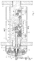
- the gripper cylinder 1 of the turning device of a sheet-fed rotary printing machine for perfecting is mounted on both sides with a bearing pin 2 of reduced diameter in the side part 3 of the machine frame. Outside of this side part 3, a fixed gear 4 is firmly connected to the end face of the bearing journal 2 by screws 5.
- an adjusting ring gear 7 is arranged concentrically about the axis 8 of the gripper cylinder 1 concentrically with the fixed gear 4.
- the frictional clamping connection between the adjusting ring gear 7 and the fixed gear 4 takes place through the reaction force of a spring 9, which is clamped between a radial projection on a switching shaft 10 penetrating the spring axially with radial play and an axially sliding disc 11 on the latter.
- a pressure ring 14 which cooperates with a threaded sleeve 15, which can be screwed onto a threaded pin at the free end of the control shaft 10 and in turn cooperates with a switching element 16 in the drive circuit of the machine, such that the threaded sleeve 15 only on the pressure ring 14 can act when the switching element 16 actuated via a rocker 17 has interrupted the drive circuit and a closing of this circuit is only possible when the spring 9 is connected the full reaction force acts on the elements of the clamp.
- the switching element 16 By screwing the threaded sleeve 15 on the threaded pin on the control shaft 10, the switching element 16 is first actuated before the threaded sleeve acts on the pressure ring and this presses the disk 11 with further prestressing of the spring 9 in the direction against the projecting collar on the control shaft 10, so that the pressure lever 12 are relieved and the clamping between the adjusting ring gear 7 and the fixed gear 4 is released.
- a screwing of the threaded sleeve 15 in the opposite direction initially has the result that the disc 11 is pressed under the action of the spring 9 against the inner ends of the pressure lever 12, and only after the reaction force of the spring is fully effective against the ends of the pressure lever 12 forms there is a space between the pressure ring 14 and the threaded sleeve 15 before the switching element 16 is released for the drive circuit via the rocker 17.
- the selector shaft 10 is axially limited movable in the gripper cylinder 1 and presses with an annular shoulder 18 against one arm of an angle lever 19 which is pivotally mounted about an axis 20 transverse to the axis 8 in a recess 21 of the gripper cylinder 1 and with the other Arm engages under a clamping bracket 22, which is connected by tension bolts 23 to the switching bridge 24, which is linearly displaceable approximately parallel to the axis 8 for gripper changeover.
- the angle lever 19 is mounted in a slide 25 which is carried out to the other end of the gripper cylinder 1 and here acts against a pendulum body 27 mounted in a recess 26, which in turn also engages under a clamping bracket 28 which is connected to the switching bridge by means of draw bolts 29 24 is connected.
- the reaction forces of the spring 9 are simultaneously effective as radial forces acting in the direction of the axis 8 for the switching bridge, so that a frictional Clamp connection between the switching bridge and the gripper cylinder is created.
- a switching wheel 30 is fastened on the drive side outside of the side part 3 on the switching shaft 10, which at the same time forms the collar projection of the switching shaft 10 for the engagement of the spring 9.
- the toothing of an idler gear 31 engages in the external toothing of this ratchet wheel 30, which on the other hand meshes with an internal toothing on the adjusting sprocket 7, so that an angular rotation of the adjusting sprocket 7 relative to the fixed gear 4 leads to a rotary movement of the selector shaft 10.
- the end of the control shaft 10 directed towards the middle of the machine passes through a bore 33 in the arm of the angle lever 19 following the annular shoulder 18 with a section of reduced diameter.
- the extension 32 is continued beyond the angle lever 19 into a recess 34.
- the free end of the extension 32 engages in a rotationally fixed but axially movable manner in a journal of an axial curve 36, which is rotatably supported with this journal in a bearing 35 in the gripper cylinder 2, so that axial movements of the control shaft 10 relative to the axial curve 36 enable the clamping .
- a pin 37 of the switching bridge 24 engages radially in the axial curve 36, so that a rotation of the axial curve 36 results in a linear displacement of the switching bridge 24.
- a roller 37a is advantageously mounted on the pin 37 in order to reduce the frictional resistances.
- the axial slope of the curve 36 extends only over a changeover angle corresponding to the axial changeover movement for the gripper control, so that an axial movement component is only transmitted to the switching bridge 24 in this angular range when the adjusting ring gear 7 is adjusted relative to the fixed gearwheel 4.
- the pin 37 extends through an elongated hole 38 in the slide 25, around the latter linear movement in the clamping and in the release of the clamping not to hinder.
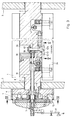
- the design and mounting of the gripper cylinder 1 and the elements of the clamping between the adjusting ring gear 7 and the fixed gear 4 correspond to the description of FIG. 1.
- the elements for converting the rotary movement of the control shaft 10 into an axial movement are different the switching bridge 24.
- a bearing pin of a bevel gear 39 is rotatably mounted in the bearing 35.
- the end of the selector shaft 10 engages in the bearing journal of this bevel gear 39 in a rotationally fixed but axially movable manner.
- the bevel gear 39 engages in the toothing of a bevel gear 40, which is attached to the shaft 41, which is mounted with its axis transverse to the axis 8 of the control shaft 10 in the gripper cylinder and carries an eccentric 42 at its free end, which engages with an eccentric roller 42a mounted eccentrically to the axis of the shaft 41 in a link 43 which is assigned to the switching bridge 24.
- a rotary movement of the selector shaft 10 also causes an axial displacement movement of the switching bridge 24.
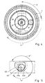
- the link 43 has a special shape, such as, for example is shown in Figure 5.
- the backdrop 43 has two straight buttons 43a and 43b, which enclose each other approximately at a right angle, one of which 43a is assigned to the straight print and the other 43b to the reverse pressure. Both buttons 43a and 43b affect the imaginary circular arc, which the outer vertex of the eccentric 42 strikes when it rotates about the axis of the shaft 41, so that they define the changeover angle x1 from face pressure to back pressure and vice versa, which is due to the transmission ratio of the gears 30 and 31 and the Internal toothing of the adjusting ring gear 7 results. Outside of these buttons 43a and 43b, i.e. outside the changeover angle x1, the eccentric 42 moves in a free space, so that during the adjustment of the adjusting ring gear 7 relative to the fixed gear 4 in the format adjustment range y (y1) there is no displacement movement of the switching bridge 24.
- FIGS. 6 to 9 execution examples for elements for stopping a gripper shaft 44 during the adjustment of the adjusting ring gear 7 relative to the fixed gear 4 are shown.
- a radial curve 45 is fastened on the selector shaft 10 and blocks a parking cam 48 on the gripper shaft 44 via a roller 46 on an angle lever 47.
- a comparable result can also be achieved according to the example of FIGS. 8 and 9 by a pair of gearwheels 49 and 50, of which one 49 is fastened on the selector shaft 10 and the other 50 has a stop bar 51 which also has a stop cam in a predetermined angular position 48 blocked on the Grelferwelle 44.
Landscapes
- Supply, Installation And Extraction Of Printed Sheets Or Plates (AREA)
- Feeding Of Articles By Means Other Than Belts Or Rollers (AREA)
Applications Claiming Priority (2)
| Application Number | Priority Date | Filing Date | Title |
|---|---|---|---|
| DE4131273 | 1991-09-20 | ||
| DE4131273A DE4131273C1 (fr) | 1991-09-20 | 1991-09-20 |
Publications (2)
| Publication Number | Publication Date |
|---|---|
| EP0532934A1 true EP0532934A1 (fr) | 1993-03-24 |
| EP0532934B1 EP0532934B1 (fr) | 1995-04-05 |
Family
ID=6441035
Family Applications (1)
| Application Number | Title | Priority Date | Filing Date |
|---|---|---|---|
| EP92114282A Expired - Lifetime EP0532934B1 (fr) | 1991-09-20 | 1992-08-21 | Dispositif de commutation de la commande des pinces d'un cylindre à pinces d'un dispositif de retournement dans une machine rotative d'impression recto-verso de feuilles |
Country Status (6)
| Country | Link |
|---|---|
| US (1) | US5213035A (fr) |
| EP (1) | EP0532934B1 (fr) |
| JP (1) | JP2862738B2 (fr) |
| CN (1) | CN1032960C (fr) |
| AT (1) | ATE120691T1 (fr) |
| DE (2) | DE4131273C1 (fr) |
Families Citing this family (11)
| Publication number | Priority date | Publication date | Assignee | Title |
|---|---|---|---|---|
| DE4218422C2 (de) * | 1992-06-04 | 1994-04-28 | Heidelberger Druckmasch Ag | Bogen-Offsetrotationsdruckmaschine mit herausnehmbarem Eindruck- oder Veredelungswerk |
| JP3328855B2 (ja) * | 1993-09-02 | 2002-09-30 | 株式会社小森コーポレーション | 反転機構付枚葉輪転印刷機 |
| JP4220581B2 (ja) * | 1995-11-15 | 2009-02-04 | ハイデルベルガー ドルツクマシーネン アクチエンゲゼルシヤフト | 印刷機における反転装置の二重歯車 |
| DE10254113A1 (de) | 2001-12-12 | 2003-06-18 | Heidelberger Druckmasch Ag | Vorrichtung zur Änderung des Betriebszustands einer Greifersteuereinrichtung in einer Bogenwendeeinrichtung einer bogenverarbeitenden Maschine |
| DE10206466A1 (de) * | 2002-02-16 | 2003-09-04 | Koenig & Bauer Ag | Vorrichtung zur Umstellung der Greifersteuerung einer Wendetrommel |
| JP4625268B2 (ja) * | 2004-04-30 | 2011-02-02 | 株式会社小森コーポレーション | 反転機構付枚葉輪転印刷機のシート状物搬送装置 |
| JP4921764B2 (ja) * | 2004-10-04 | 2012-04-25 | ハイデルベルガー ドルツクマシーネン アクチエンゲゼルシヤフト | 枚葉紙を処理する機械の反転装置でつめ制御を切り換えるための装置 |
| DE102006033104A1 (de) * | 2006-07-18 | 2008-01-24 | Heidelberger Druckmaschinen Ag | Bogenoffsetdruckmaschine |
| JP2008044373A (ja) * | 2006-08-16 | 2008-02-28 | Heidelberger Druckmas Ag | シートを処理する機械において反転グリッパを開放して旋回させるための装置 |
| US7735829B2 (en) * | 2006-11-06 | 2010-06-15 | Heidelberger Druckmaschinen Ag | Method and apparatus for turning a sheet during its transport through a printing press |
| CN101301809B (zh) * | 2007-05-11 | 2012-05-30 | 海德堡印刷机械股份公司 | 单张纸印刷机印刷装置之间的递纸辊 |
Citations (1)
| Publication number | Priority date | Publication date | Assignee | Title |
|---|---|---|---|---|
| DE4004352C1 (fr) * | 1990-02-13 | 1991-06-06 | Heidelberger Druckmaschinen Ag, 6900 Heidelberg, De |
Family Cites Families (8)
| Publication number | Priority date | Publication date | Assignee | Title |
|---|---|---|---|---|
| JPH0696285B2 (ja) * | 1986-08-25 | 1994-11-30 | 株式会社小森コーポレーション | 反転機構付枚葉印刷機の印刷切替装置 |
| US4831929A (en) * | 1987-10-21 | 1989-05-23 | Komori Printing Machinery Co., Ltd. | Suction member fixing apparatus for sheet-fed printing press with turn-over mechanism |
| DE3814831C1 (fr) * | 1988-05-02 | 1989-10-26 | Heidelberger Druckmaschinen Ag, 6900 Heidelberg, De | |
| DE3820026A1 (de) * | 1988-06-13 | 1989-12-14 | Heidelberger Druckmasch Ag | Vorrichtung zur kraftschluessigen kupplung eines festzahnrades und eines verstellzahnrades an einem zylinder einer wendeeinrichtung in einer bogenrotationsdruckmaschine und elektrische absicherung einer solchen vorrichtung |
| DE3900818C1 (fr) * | 1989-01-13 | 1990-05-10 | Heidelberger Druckmaschinen Ag, 6900 Heidelberg, De | |
| DE3900820C1 (fr) * | 1989-01-13 | 1990-05-10 | Heidelberger Druckmaschinen Ag, 6900 Heidelberg, De | |
| DE3911609A1 (de) * | 1989-04-08 | 1990-10-11 | Heidelberger Druckmasch Ag | Bogenrotationsdruckmaschine mit mehreren druckwerken zum schoendruck und schoen- und widerdruck |
| DE3911630A1 (de) * | 1989-04-10 | 1990-10-11 | Heidelberger Druckmasch Ag | Vorrichtung zur formatverstellung an bogenfuehrungstrommeln einer druckmaschine |
-
1991
- 1991-09-20 DE DE4131273A patent/DE4131273C1/de not_active Expired - Lifetime
-
1992
- 1992-08-21 EP EP92114282A patent/EP0532934B1/fr not_active Expired - Lifetime
- 1992-08-21 DE DE59201831T patent/DE59201831D1/de not_active Expired - Lifetime
- 1992-08-21 AT AT92114282T patent/ATE120691T1/de active
- 1992-09-18 CN CN92110434A patent/CN1032960C/zh not_active Expired - Fee Related
- 1992-09-21 JP JP4251417A patent/JP2862738B2/ja not_active Expired - Fee Related
- 1992-09-21 US US07/948,238 patent/US5213035A/en not_active Expired - Lifetime
Patent Citations (1)
| Publication number | Priority date | Publication date | Assignee | Title |
|---|---|---|---|---|
| DE4004352C1 (fr) * | 1990-02-13 | 1991-06-06 | Heidelberger Druckmaschinen Ag, 6900 Heidelberg, De |
Also Published As
| Publication number | Publication date |
|---|---|
| US5213035A (en) | 1993-05-25 |
| JPH05200982A (ja) | 1993-08-10 |
| DE4131273C1 (fr) | 1992-12-10 |
| JP2862738B2 (ja) | 1999-03-03 |
| ATE120691T1 (de) | 1995-04-15 |
| EP0532934B1 (fr) | 1995-04-05 |
| CN1072374A (zh) | 1993-05-26 |
| DE59201831D1 (de) | 1995-05-11 |
| CN1032960C (zh) | 1996-10-09 |
Similar Documents
| Publication | Publication Date | Title |
|---|---|---|
| DE68911847T2 (de) | Übergabevorrichtung für Gegenstände mit Greifer. | |
| EP1260441B1 (fr) | Dispositif de cerclage manuel pour lier des paquets avec une bande en acier | |
| DE602005004774T2 (de) | Fahrradgangschaltmechanismus | |
| EP0340452B1 (fr) | Dispositif de réglage en rotation d'un cylindre d'un dispositif de retournement et dispositif de déplacement axial d'un élément de réglage pour le changement de la position des pinces de ce cylindre dans une rotative d'impression de feuilles | |
| EP0532934B1 (fr) | Dispositif de commutation de la commande des pinces d'un cylindre à pinces d'un dispositif de retournement dans une machine rotative d'impression recto-verso de feuilles | |
| DE3911609C2 (fr) | ||
| DE2102412B2 (de) | Verstellvorrichtung an kurbelwellenschleifmaschinen zum ausrichten der zu schleifenden kurbelzapfen | |
| EP0377860B1 (fr) | Tambour de transfert de feuilles pour machines à imprimer pour l'impression sur le premier côté ou en retiration | |
| EP0442265B1 (fr) | Accouplement de serrage pour un composant de réglage déplaçable axialement pour le changement de rotation de la griffe sur une rotative typographique | |
| EP0742063B1 (fr) | Tourelle porte-outil | |
| DE3229869C2 (fr) | ||
| DE2720673B2 (de) | Vorrichtung zum ungleichförmigen Spannen eines Gummituches in einer Offsetdruckmaschine | |
| DE3605523A1 (de) | Wendegreifvorrichtung fuer eine einseitige und doppelseitige druckmaschine | |
| DE19602568C2 (de) | Vorrichtung zum Druckan-/ und -abstellen eines Zylinders | |
| DE3900820C1 (fr) | ||
| DE2521139C2 (de) | Durch Federkraft verstellbare Schaltvorrichtung | |
| DE3905250C2 (fr) | ||
| DE10149821B4 (de) | Einrichtung zum Steuern der Greifer eines Vorgreifers | |
| DE1436529C3 (fr) | ||
| EP0353652A2 (fr) | Dispositif supplémentaire pour montage sur une machine d'impression offset | |
| DE10206466A1 (de) | Vorrichtung zur Umstellung der Greifersteuerung einer Wendetrommel | |
| DE102004045098B4 (de) | Vorrichtung zur fernsteuerbaren Betätigung von Klemmelementen | |
| EP1297953B1 (fr) | Dispositif de conversion d'un système à pinces | |
| DE2241687C3 (de) | Antriebsvorrichtung zum oszillierenden Antreiben einer Vorschubeinrichtung | |
| DE2706351B2 (de) | Materialeinzugsvorrichtung an Draht- und/oder Bandbearbeitungsmaschinen |
Legal Events
| Date | Code | Title | Description |
|---|---|---|---|
| PUAI | Public reference made under article 153(3) epc to a published international application that has entered the european phase |
Free format text: ORIGINAL CODE: 0009012 |
|
| 17P | Request for examination filed |
Effective date: 19920821 |
|
| AK | Designated contracting states |
Kind code of ref document: A1 Designated state(s): AT CH DE FR GB IT LI SE |
|
| GBC | Gb: translation of claims filed (gb section 78(7)/1977) | ||
| 17Q | First examination report despatched |
Effective date: 19940914 |
|
| GRAA | (expected) grant |
Free format text: ORIGINAL CODE: 0009210 |
|
| AK | Designated contracting states |
Kind code of ref document: B1 Designated state(s): AT CH DE FR GB IT LI SE |
|
| REF | Corresponds to: |
Ref document number: 120691 Country of ref document: AT Date of ref document: 19950415 Kind code of ref document: T |
|
| REF | Corresponds to: |
Ref document number: 59201831 Country of ref document: DE Date of ref document: 19950511 |
|
| ITF | It: translation for a ep patent filed | ||
| ET | Fr: translation filed | ||
| GBT | Gb: translation of ep patent filed (gb section 77(6)(a)/1977) |
Effective date: 19950612 |
|
| PLBE | No opposition filed within time limit |
Free format text: ORIGINAL CODE: 0009261 |
|
| 26N | No opposition filed | ||
| PGFP | Annual fee paid to national office [announced via postgrant information from national office to epo] |
Ref country code: GB Payment date: 19990726 Year of fee payment: 8 |
|
| PGFP | Annual fee paid to national office [announced via postgrant information from national office to epo] |
Ref country code: AT Payment date: 19990817 Year of fee payment: 8 |
|
| PGFP | Annual fee paid to national office [announced via postgrant information from national office to epo] |
Ref country code: SE Payment date: 19990820 Year of fee payment: 8 |
|
| PGFP | Annual fee paid to national office [announced via postgrant information from national office to epo] |
Ref country code: FR Payment date: 19990826 Year of fee payment: 8 |
|
| PGFP | Annual fee paid to national office [announced via postgrant information from national office to epo] |
Ref country code: CH Payment date: 19990908 Year of fee payment: 8 |
|
| PG25 | Lapsed in a contracting state [announced via postgrant information from national office to epo] |
Ref country code: AT Free format text: LAPSE BECAUSE OF NON-PAYMENT OF DUE FEES Effective date: 20000821 Ref country code: GB Free format text: LAPSE BECAUSE OF NON-PAYMENT OF DUE FEES Effective date: 20000821 |
|
| PG25 | Lapsed in a contracting state [announced via postgrant information from national office to epo] |
Ref country code: SE Free format text: LAPSE BECAUSE OF NON-PAYMENT OF DUE FEES Effective date: 20000822 |
|
| PG25 | Lapsed in a contracting state [announced via postgrant information from national office to epo] |
Ref country code: CH Free format text: LAPSE BECAUSE OF NON-PAYMENT OF DUE FEES Effective date: 20000831 Ref country code: LI Free format text: LAPSE BECAUSE OF NON-PAYMENT OF DUE FEES Effective date: 20000831 |
|
| GBPC | Gb: european patent ceased through non-payment of renewal fee |
Effective date: 20000821 |
|
| REG | Reference to a national code |
Ref country code: CH Ref legal event code: PL |
|
| EUG | Se: european patent has lapsed |
Ref document number: 92114282.4 |
|
| PG25 | Lapsed in a contracting state [announced via postgrant information from national office to epo] |
Ref country code: FR Free format text: LAPSE BECAUSE OF NON-PAYMENT OF DUE FEES Effective date: 20010430 |
|
| REG | Reference to a national code |
Ref country code: FR Ref legal event code: ST |
|
| PG25 | Lapsed in a contracting state [announced via postgrant information from national office to epo] |
Ref country code: IT Free format text: LAPSE BECAUSE OF NON-PAYMENT OF DUE FEES;WARNING: LAPSES OF ITALIAN PATENTS WITH EFFECTIVE DATE BEFORE 2007 MAY HAVE OCCURRED AT ANY TIME BEFORE 2007. THE CORRECT EFFECTIVE DATE MAY BE DIFFERENT FROM THE ONE RECORDED. Effective date: 20050821 |
|
| PGFP | Annual fee paid to national office [announced via postgrant information from national office to epo] |
Ref country code: DE Payment date: 20090827 Year of fee payment: 18 |
|
| REG | Reference to a national code |
Ref country code: DE Ref legal event code: R119 Ref document number: 59201831 Country of ref document: DE Effective date: 20110301 |
|
| PG25 | Lapsed in a contracting state [announced via postgrant information from national office to epo] |
Ref country code: DE Free format text: LAPSE BECAUSE OF NON-PAYMENT OF DUE FEES Effective date: 20110301 |