EP0532977A2 - Système de poursuite d'un aéronef - Google Patents
Système de poursuite d'un aéronef Download PDFInfo
- Publication number
- EP0532977A2 EP0532977A2 EP92114948A EP92114948A EP0532977A2 EP 0532977 A2 EP0532977 A2 EP 0532977A2 EP 92114948 A EP92114948 A EP 92114948A EP 92114948 A EP92114948 A EP 92114948A EP 0532977 A2 EP0532977 A2 EP 0532977A2
- Authority
- EP
- European Patent Office
- Prior art keywords
- location system
- missile
- laser
- light set
- command
- Prior art date
- Legal status (The legal status is an assumption and is not a legal conclusion. Google has not performed a legal analysis and makes no representation as to the accuracy of the status listed.)
- Withdrawn
Links
Images
Classifications
-
- G—PHYSICS
- G01—MEASURING; TESTING
- G01S—RADIO DIRECTION-FINDING; RADIO NAVIGATION; DETERMINING DISTANCE OR VELOCITY BY USE OF RADIO WAVES; LOCATING OR PRESENCE-DETECTING BY USE OF THE REFLECTION OR RERADIATION OF RADIO WAVES; ANALOGOUS ARRANGEMENTS USING OTHER WAVES
- G01S17/00—Systems using the reflection or reradiation of electromagnetic waves other than radio waves, e.g. lidar systems
- G01S17/66—Tracking systems using electromagnetic waves other than radio waves
-
- F—MECHANICAL ENGINEERING; LIGHTING; HEATING; WEAPONS; BLASTING
- F41—WEAPONS
- F41G—WEAPON SIGHTS; AIMING
- F41G7/00—Direction control systems for self-propelled missiles
- F41G7/20—Direction control systems for self-propelled missiles based on continuous observation of target position
- F41G7/30—Command link guidance systems
- F41G7/301—Details
- F41G7/306—Details for transmitting guidance signals
-
- F—MECHANICAL ENGINEERING; LIGHTING; HEATING; WEAPONS; BLASTING
- F42—AMMUNITION; BLASTING
- F42B—EXPLOSIVE CHARGES, e.g. FOR BLASTING, FIREWORKS, AMMUNITION
- F42B12/00—Projectiles, missiles or mines characterised by the warhead, the intended effect, or the material
- F42B12/02—Projectiles, missiles or mines characterised by the warhead, the intended effect, or the material characterised by the warhead or the intended effect
- F42B12/36—Projectiles, missiles or mines characterised by the warhead, the intended effect, or the material characterised by the warhead or the intended effect for dispensing materials; for producing chemical or physical reaction; for signalling ; for transmitting information
- F42B12/38—Projectiles, missiles or mines characterised by the warhead, the intended effect, or the material characterised by the warhead or the intended effect for dispensing materials; for producing chemical or physical reaction; for signalling ; for transmitting information of tracer type
- F42B12/382—Projectiles, missiles or mines characterised by the warhead, the intended effect, or the material characterised by the warhead or the intended effect for dispensing materials; for producing chemical or physical reaction; for signalling ; for transmitting information of tracer type emitting an electromagnetic radiation, e.g. laser beam or infrared emission
-
- F—MECHANICAL ENGINEERING; LIGHTING; HEATING; WEAPONS; BLASTING
- F42—AMMUNITION; BLASTING
- F42B—EXPLOSIVE CHARGES, e.g. FOR BLASTING, FIREWORKS, AMMUNITION
- F42B12/00—Projectiles, missiles or mines characterised by the warhead, the intended effect, or the material
- F42B12/02—Projectiles, missiles or mines characterised by the warhead, the intended effect, or the material characterised by the warhead or the intended effect
- F42B12/36—Projectiles, missiles or mines characterised by the warhead, the intended effect, or the material characterised by the warhead or the intended effect for dispensing materials; for producing chemical or physical reaction; for signalling ; for transmitting information
- F42B12/38—Projectiles, missiles or mines characterised by the warhead, the intended effect, or the material characterised by the warhead or the intended effect for dispensing materials; for producing chemical or physical reaction; for signalling ; for transmitting information of tracer type
- F42B12/387—Passive tracers, e.g. using a reflector mounted on the projectile
-
- G—PHYSICS
- G05—CONTROLLING; REGULATING
- G05D—SYSTEMS FOR CONTROLLING OR REGULATING NON-ELECTRIC VARIABLES
- G05D1/00—Control of position, course, altitude or attitude of land, water, air or space vehicles, e.g. using automatic pilots
- G05D1/0011—Control of position, course, altitude or attitude of land, water, air or space vehicles, e.g. using automatic pilots associated with a remote control arrangement
Definitions
- the invention relates to a missile location system according to the preamble of claim 1.
- Missile location systems have also become known in a wide variety of embodiments by the applicant.
- non-modulated light sets such as pyrotechnical light sets, lamps, CW lasers or slowly modulated glow emitters with mechanical modulators or similar concepts, are used as light sets for optronally guided missiles FK, or rapidly modulated light sets at short wavelengths - i.e. diode lasers, xenon flash lamps, etc. . - used.
- the invention has for its object to provide a missile location system of the type mentioned, which is free of the aforementioned disadvantages of the prior art, so that trouble-free location over a long range is achieved.
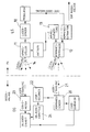
- the exemplary embodiment sketched in the figure of the drawing shows a suitable combination of a long-wave, quickly coded laser light set LS with a laser command transmitter of the locating device OG of the floor system.
- the abovementioned quickly coded laser light set LS is attached to the rear of the missile FK, the beam angle a of which can be changed so quickly with optical means relative to the longitudinal axis of the missile using optical means - for example a rotating wedge pair with a diameter of only a few millimeters - that the laser radiation is the receiver of the ground system always illuminated even with the fastest FK movements.
- the angular range that the laser light set LS illuminates can be narrowed down to the tolerance of the radiation tracking - for example to 1 °, so that high power densities and thus long ranges can be achieved with relatively low laser powers (in the range of 4 W).
- the angle information must first be obtained for tracking the radiation cone. This is done in that a laser transmitter 20 is used as the command transmitter, which is tracked to the missile FK on the basis of the coordinates determined in the locating device OG.
- the light set LS is composed of a light set assembly and a command receiver unit, both parts being combined to form a rigid, harmonized unit, thus ensuring the parallelism of the two optical axes.
- the command receiver 12 is equipped with a position-giving detector. The evaluation of the detector signals shows the direction from the missile FK to the locating device OG, which is used to track the light emitting cone.
- the determination of the missile coordinates in the locating device OG is carried out in a manner similar to the previously described determination of the direction FK to OG, namely in the goniometer 23 with a position-giving detector.
- a position-giving detector In addition to classic modulation disc goniometers, quadrant or lateral effect detectors are also used.
- An advantage over imaging goniometers is that the diffraction at the entrance lens does not play a major role for the accuracy that can be achieved, so that advantages in terms of size and cost and thus economy are achieved, particularly in the long-wave IR range.
- the optical element required for widening - contained in the exemplary embodiment in the radiation angle adjuster 11 - is a prism with a diameter of only a few millimeters, which is pulled out of the beam path in a time-controlled manner, for example with spring tension, whereupon the beam tracking is put into operation.
- the beam tracking will made by angle adjuster 11, for example with a small pair of rotary wedges.
- the code for the modulation is generated and varied in the locating device OG of the ground system and transmitted to the missile FK via the command line.
- the composition and function of the proposed missile location system should clearly emerge from the figure of the drawing, so that no further explanations appear to be necessary for this.
- the angle evaluation unit of the command receiver unit in the LS is designated, with 10 the laser transmitter of the light set assembly, with 20 the command laser transmitter of the floor system, with 22 the steering computer in the upper floor and with 24 the unit for determining the storage in the upper floor.
Landscapes
- Engineering & Computer Science (AREA)
- Physics & Mathematics (AREA)
- Chemical & Material Sciences (AREA)
- General Engineering & Computer Science (AREA)
- Combustion & Propulsion (AREA)
- Electromagnetism (AREA)
- Radar, Positioning & Navigation (AREA)
- Remote Sensing (AREA)
- General Physics & Mathematics (AREA)
- Computer Networks & Wireless Communication (AREA)
- Automation & Control Theory (AREA)
- Aviation & Aerospace Engineering (AREA)
- Health & Medical Sciences (AREA)
- Optics & Photonics (AREA)
- Toxicology (AREA)
- Aiming, Guidance, Guns With A Light Source, Armor, Camouflage, And Targets (AREA)
Applications Claiming Priority (2)
| Application Number | Priority Date | Filing Date | Title |
|---|---|---|---|
| DE4130617A DE4130617C1 (fr) | 1991-09-14 | 1991-09-14 | |
| DE4130617 | 1991-09-14 |
Publications (2)
| Publication Number | Publication Date |
|---|---|
| EP0532977A2 true EP0532977A2 (fr) | 1993-03-24 |
| EP0532977A3 EP0532977A3 (en) | 1993-06-09 |
Family
ID=6440614
Family Applications (1)
| Application Number | Title | Priority Date | Filing Date |
|---|---|---|---|
| EP19920114948 Withdrawn EP0532977A3 (en) | 1991-09-14 | 1992-09-02 | Aircraft tracking system |
Country Status (2)
| Country | Link |
|---|---|
| EP (1) | EP0532977A3 (fr) |
| DE (1) | DE4130617C1 (fr) |
Cited By (1)
| Publication number | Priority date | Publication date | Assignee | Title |
|---|---|---|---|---|
| WO2011093757A1 (fr) | 2010-01-29 | 2011-08-04 | Saab Ab | Système et procédé pour suivre et guider au moins un objet |
Families Citing this family (2)
| Publication number | Priority date | Publication date | Assignee | Title |
|---|---|---|---|---|
| RU2183023C2 (ru) * | 2000-05-12 | 2002-05-27 | Григорьев Владимир Григорьевич | Способ ориентации поля зрения системы обзора |
| DE102007053730B4 (de) * | 2007-11-10 | 2013-11-07 | Diehl Bgt Defence Gmbh & Co. Kg | Zielführungsvorrichtung |
Family Cites Families (6)
| Publication number | Priority date | Publication date | Assignee | Title |
|---|---|---|---|---|
| US3598344A (en) * | 1964-06-01 | 1971-08-10 | Philco Ford Corp | Missile command system |
| DE2655306C3 (de) * | 1976-12-07 | 1981-07-09 | Messerschmitt-Bölkow-Blohm GmbH, 8000 München | Verfahren und Vorrichtung zur Ausblendung von Störstrahlern in einer Einrichtung zur optischen Lenkung von Flugkörpern |
| DE2812915C2 (de) * | 1978-03-23 | 1986-09-18 | Precitronic Gesellschaft für Feinmechanik und Electronic mbH, 2000 Hamburg | Geschoß mit Laser |
| US4247059A (en) * | 1978-10-25 | 1981-01-27 | The United States Of America As Represented By The Secretary Of The Army | Light emitting diode beacons for command guidance missile track links |
| DE3218874C1 (de) * | 1982-05-19 | 1986-07-17 | Messerschmitt-Bölkow-Blohm GmbH, 8012 Ottobrunn | Leuchtsatz mit pyrotechnischen Leuchtmaterialien |
| DE3812984C1 (en) * | 1988-04-19 | 1991-07-18 | Eltro Gmbh, Gesellschaft Fuer Strahlungstechnik, 6900 Heidelberg, De | Continuously locating and guiding missile or aircraft - measuring laser radiation returned from on-board reflector using transceiver goniometer unit |
-
1991
- 1991-09-14 DE DE4130617A patent/DE4130617C1/de not_active Expired - Fee Related
-
1992
- 1992-09-02 EP EP19920114948 patent/EP0532977A3/de not_active Withdrawn
Cited By (2)
| Publication number | Priority date | Publication date | Assignee | Title |
|---|---|---|---|---|
| WO2011093757A1 (fr) | 2010-01-29 | 2011-08-04 | Saab Ab | Système et procédé pour suivre et guider au moins un objet |
| US9000340B2 (en) | 2010-01-29 | 2015-04-07 | Saab Ab | System and method for tracking and guiding at least one object |
Also Published As
| Publication number | Publication date |
|---|---|
| EP0532977A3 (en) | 1993-06-09 |
| DE4130617C1 (fr) | 1993-02-11 |
Similar Documents
| Publication | Publication Date | Title |
|---|---|---|
| DE4042730B4 (de) | Anordnung zur Verbesserung der Sicht in Fahrzeugen | |
| CH693578A5 (de) | Verfahren und Vorrichtung zur Zielsuche für geodätische Geräte. | |
| EP1118494B1 (fr) | Procédé pour aligner un capteur dans un système de commande de vitesse adaptatif dans un véhicule | |
| DE4010220A1 (de) | Vorrichtung zum ermitteln des abstands zwischen zwei kraftfahrzeugen | |
| DE2409563A1 (de) | Verfahren und vorrichtung fuer die zielfuehrung | |
| DE102017127813B4 (de) | Kommunikationsplattform und Kommunikationssystem nebst zugehörigem Verfahren zur Strahlausrichtung in unidirektionalen optischen Kommunikationssystemen | |
| DE3036257A1 (de) | Vorrichtung zur elektro-optischen abstandsmessung | |
| DE2152677A1 (de) | Fernlenksystem zur Fuehrung eines Flugkoerpers zu einem Ziel | |
| DE69313594T2 (de) | Justierungsmechanismus für einen Multisensor mit gemeinsamer Apertur | |
| DE4416210A1 (de) | Verfahren und Vorrichtung zur Ermittlung der Rollwinkellage eines rotierenden Flugkörpers | |
| DE3121488A1 (de) | Einrichtung zur schusssimulation von visiergesteuerten lenkflugkoerpern | |
| EP0120329A2 (fr) | Système de balayage électromagnétique | |
| DE2214556B2 (de) | Navigations-Sender | |
| DE1506099C3 (de) | Fernlenksystem zum Lenken von Flugkörpern in ein von einer Strahlungsquelle mit Infrarotlicht angestrahltes Ziel | |
| DE102016115277A1 (de) | Optische Vorrichtung | |
| DE3049100C2 (fr) | ||
| EP0532977A2 (fr) | Système de poursuite d'un aéronef | |
| DE2853695C2 (de) | Vorrichtung zum selbsttätigen Nachführen eines Laserstrahls | |
| WO2019137643A1 (fr) | Procédé et dispositif de suivi optique de cible d'un objet cible pouvant être irradié par un laser à haute énergie | |
| DE2850743A1 (de) | Opto-elektronische messung der sendestrahlrichtung eines lidars | |
| DE2611478A1 (de) | Tomographieanordnung | |
| DE1962174A1 (de) | Optisches Entfernungsmessgeraet | |
| GB2089061A (en) | Optical fibre-beam expander alignment testing | |
| EP0246354B1 (fr) | Dispositif opto-électronique | |
| DE3601386C1 (en) | Method and device for calibrating optical rangefinders |
Legal Events
| Date | Code | Title | Description |
|---|---|---|---|
| PUAI | Public reference made under article 153(3) epc to a published international application that has entered the european phase |
Free format text: ORIGINAL CODE: 0009012 |
|
| AK | Designated contracting states |
Kind code of ref document: A2 Designated state(s): BE DE ES FR GB IT LU NL SE |
|
| PUAL | Search report despatched |
Free format text: ORIGINAL CODE: 0009013 |
|
| AK | Designated contracting states |
Kind code of ref document: A3 Designated state(s): BE DE ES FR GB IT LU NL SE |
|
| 17P | Request for examination filed |
Effective date: 19930521 |
|
| 17Q | First examination report despatched |
Effective date: 19931229 |
|
| 18W | Application withdrawn |
Withdrawal date: 19940319 |