EP0532990A2 - Vis autotarandeuse, procédé pour sa fabrication et matrices de laminage pour la mise en oeuvre du procédé - Google Patents
Vis autotarandeuse, procédé pour sa fabrication et matrices de laminage pour la mise en oeuvre du procédé Download PDFInfo
- Publication number
- EP0532990A2 EP0532990A2 EP92115118A EP92115118A EP0532990A2 EP 0532990 A2 EP0532990 A2 EP 0532990A2 EP 92115118 A EP92115118 A EP 92115118A EP 92115118 A EP92115118 A EP 92115118A EP 0532990 A2 EP0532990 A2 EP 0532990A2
- Authority
- EP
- European Patent Office
- Prior art keywords
- thread
- diameter
- shaft
- pin
- screw
- Prior art date
- Legal status (The legal status is an assumption and is not a legal conclusion. Google has not performed a legal analysis and makes no representation as to the accuracy of the status listed.)
- Withdrawn
Links
Images


Classifications
-
- F—MECHANICAL ENGINEERING; LIGHTING; HEATING; WEAPONS; BLASTING
- F16—ENGINEERING ELEMENTS AND UNITS; GENERAL MEASURES FOR PRODUCING AND MAINTAINING EFFECTIVE FUNCTIONING OF MACHINES OR INSTALLATIONS; THERMAL INSULATION IN GENERAL
- F16B—DEVICES FOR FASTENING OR SECURING CONSTRUCTIONAL ELEMENTS OR MACHINE PARTS TOGETHER, e.g. NAILS, BOLTS, CIRCLIPS, CLAMPS, CLIPS OR WEDGES; JOINTS OR JOINTING
- F16B25/00—Screws that cut thread in the body into which they are screwed, e.g. wood screws
- F16B25/0036—Screws that cut thread in the body into which they are screwed, e.g. wood screws characterised by geometric details of the screw
- F16B25/0042—Screws that cut thread in the body into which they are screwed, e.g. wood screws characterised by geometric details of the screw characterised by the geometry of the thread, the thread being a ridge wrapped around the shaft of the screw
- F16B25/0057—Screws that cut thread in the body into which they are screwed, e.g. wood screws characterised by geometric details of the screw characterised by the geometry of the thread, the thread being a ridge wrapped around the shaft of the screw the screw having distinct axial zones, e.g. multiple axial thread sections with different pitch or thread cross-sections
-
- B—PERFORMING OPERATIONS; TRANSPORTING
- B21—MECHANICAL METAL-WORKING WITHOUT ESSENTIALLY REMOVING MATERIAL; PUNCHING METAL
- B21H—MAKING PARTICULAR METAL OBJECTS BY ROLLING, e.g. SCREWS, WHEELS, RINGS, BARRELS, BALLS
- B21H3/00—Making helical bodies or bodies having parts of helical shape
- B21H3/02—Making helical bodies or bodies having parts of helical shape external screw-threads ; Making dies for thread rolling
- B21H3/027—Rolling of self-tapping screws
-
- F—MECHANICAL ENGINEERING; LIGHTING; HEATING; WEAPONS; BLASTING
- F16—ENGINEERING ELEMENTS AND UNITS; GENERAL MEASURES FOR PRODUCING AND MAINTAINING EFFECTIVE FUNCTIONING OF MACHINES OR INSTALLATIONS; THERMAL INSULATION IN GENERAL
- F16B—DEVICES FOR FASTENING OR SECURING CONSTRUCTIONAL ELEMENTS OR MACHINE PARTS TOGETHER, e.g. NAILS, BOLTS, CIRCLIPS, CLAMPS, CLIPS OR WEDGES; JOINTS OR JOINTING
- F16B25/00—Screws that cut thread in the body into which they are screwed, e.g. wood screws
- F16B25/001—Screws that cut thread in the body into which they are screwed, e.g. wood screws characterised by the material of the body into which the screw is screwed
- F16B25/0021—Screws that cut thread in the body into which they are screwed, e.g. wood screws characterised by the material of the body into which the screw is screwed the material being metal, e.g. sheet-metal or aluminium
-
- F—MECHANICAL ENGINEERING; LIGHTING; HEATING; WEAPONS; BLASTING
- F16—ENGINEERING ELEMENTS AND UNITS; GENERAL MEASURES FOR PRODUCING AND MAINTAINING EFFECTIVE FUNCTIONING OF MACHINES OR INSTALLATIONS; THERMAL INSULATION IN GENERAL
- F16B—DEVICES FOR FASTENING OR SECURING CONSTRUCTIONAL ELEMENTS OR MACHINE PARTS TOGETHER, e.g. NAILS, BOLTS, CIRCLIPS, CLAMPS, CLIPS OR WEDGES; JOINTS OR JOINTING
- F16B25/00—Screws that cut thread in the body into which they are screwed, e.g. wood screws
- F16B25/0036—Screws that cut thread in the body into which they are screwed, e.g. wood screws characterised by geometric details of the screw
- F16B25/0042—Screws that cut thread in the body into which they are screwed, e.g. wood screws characterised by geometric details of the screw characterised by the geometry of the thread, the thread being a ridge wrapped around the shaft of the screw
- F16B25/0052—Screws that cut thread in the body into which they are screwed, e.g. wood screws characterised by geometric details of the screw characterised by the geometry of the thread, the thread being a ridge wrapped around the shaft of the screw the ridge having indentations, notches or the like in order to improve the cutting behaviour
Definitions
- the invention relates to a thread-forming screw in which the shaft has a continuously circular core cross-section over its entire length and in which the thread curled into this shaft also has a circular outer circumferential limitation.
- a thread-forming screw equipped with such features is already known from DE-PS 27 03 433.
- the thread curled into the shaft has circumferential sections extending in the longitudinal direction of the screw and protruding from the thread flanks and the thread tip of the thread profile and in one piece the material of the screw shaft is formed on the thread flanks and thread tip.
- This known screw has proven itself in practice and is characterized in that the cusps lie on the entire length of the screw shaft circumferential portions of constant width, the thread evenly, with a much larger pitch than that of the thread, helically around the shaft circumference are continuously superimposed and have the same pitch direction as the thread.
- nut threads can be created with only a few screwing moments, which are true to teaching along their entire length. This advantage is achieved in that the material to be displaced during the tapping process of the nut thread is displaced from each hump in the direction of the adjacent thread flank, and in this way the screw can be screwed in with a low screwing torque.
- the penetration section of the screw shaft between the penetration side and a beveled formation of the tapping thread was therefore equipped with a so-called pilot thread, the tip cross section of which is essentially uniform over a 360 ° circumference and to avoid these disadvantages whose maximum tip dimension is smaller than the maximum tip dimension of the tapping thread in the area of the beveled thread formation.
- the pilot thread is intended to stabilize the vertical initial position of the screw relative to the workpiece or to ensure the coaxial alignment of the screw shaft axis with the hole axis, so that the critical start of thread formation is facilitated and the correct relative position of the screwed-in screw in the workpiece is ensured.
- the invention has for its object to provide a self-tapping screw of the type specified, the one automatic axial alignment of their shank to the hole to be provided with the tapping thread in the workpiece already at the critical start of thread forming, but at the same time enables and permits simple and inexpensive screw production with the help of roller jaw designs, as are common for the production of thread-forming screws of the generic type .
- the predetermined length of the cylindrically stepped pin corresponds to a dimension which is between two and four thread pitch intervals and is preferably three pitch pitches of the thread.
- the - larger - diameter of the shaft on the blank is in a ratio between 0.85: 1 and 0.9: 1 to the nominal size of the thread fully formed on it, while the - smaller - diameter of the pin on the blank has a ratio between 0.9: 1 and 0.98: 1 to the diameter of the fragmentarily profiled threaded section.
- the invention also provides that the pin of the blank has a conical end phase, while there is also a conical transition phase between this pin and the shaft. It has proven useful if the cone angle of the final phase is larger, preferably approximately twice as large as the cone angle of the transition phase.
- the training measures outlined above can also be realized with thread-forming screws, in which the thread rolled into the shaft has bumps on circumferential sections running in the longitudinal direction of the screw, which run over the thread flanks and the thread tip of the thread profile and are made in one piece from the material of the screw shaft onto the thread flanks and Thread tips are shaped.
- the humps at least over the thread length of the screw shaft having the fully formed thread profile running circumferential sections of constant width, which are uniformly superimposed on the thread with a substantially greater pitch than that of the thread, running helically around the shaft circumference and have the same pitch direction as the thread.
- a method according to the invention for the production of thread-forming screws by pressing the threads by means of grooved flat jaws on thread rolling machines is essentially characterized in that screw blanks are inserted with a shaft that is cylindrically stepped in a pin-like manner at its free end over a predetermined length section the thread is rolled onto this with a core diameter that is the same over its entire length but falls short of the pin diameter, and that the rolling process of the thread profile is used to completely and / or with the nominal diameter only over the length range of the larger shaft diameter.
- the screw blanks can be used in this manufacturing process with a tensile strength of about 40 to 70 kp / mm2.
- Rolling jaws for carrying out this method which are provided with a groove profile corresponding to the thread cross section, are distinguished according to the invention in that they correspond to at least the entire shaft length of a blank Width and with a constant depth over this entire width are provided for the groove profile corresponding to the complete thread cross-section, whereby on the one hand the groove ridges and on the other hand the groove feet on the flat jaws each lie over the entire width on a common plane.
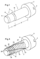
- the screw blank 1 shows a screw blank 1 from which a thread-forming screw 2 is to be produced, as can be seen from FIG. 3 of the drawing.
- the screw blank 1 has a head 3 which, for example, has an at least approximately cylindrical shape and, on its free end face, contains a tool engagement 4, for example a diametrical or cross recess.
- a shaft 5 adjoins the head 3 of the screw blank 3 in one piece, which has a circular cross section over its entire length and has two cylindrical longitudinal sections 6 and 7.
- the length section 7 forming the free end of the shaft 5 is designed as a pin 8 set off to a smaller diameter, which has a conical end phase 9 and is equipped with a likewise conical transition phase 10 towards the length section 6.
- the cylindrical pin 8 formed by the length section 7 and offset to a smaller diameter has a length which corresponds to only a fraction of the length of the length section 6 on the shaft 5 with the larger diameter.
- This length of the cylindrically stepped pin 8 can correspond to a dimension that lies between two and four thread pitch sections and is preferably three pitch spacings of the thread to be applied.
- the larger diameter 11 of the shaft 5 on the blank 1 in the region of the length section 6 can be in a ratio of 1: 0.9 to 1: 0.96 to the smaller diameter of the same in the length section 7 of the pin 8 and in preferred cases 1: 0, 93.
- the cone angle 13 for the end phase 9 of the pin 8 is larger, preferably about twice as large, as the cone angle 14 for the transition phase 10 between the pin 8 and the length section 6 of the shaft adjoining it towards the head 3 5. It has proven useful to give the end phase 9 a cone angle 13 of 60 ° and to provide the transition phase 10 with a cone angle 14 of 26 °.
- a thread 15 is rolled into the shaft 5 of the screw blank 1, specifically with a core diameter 16 which not only has the larger diameter 11 in the length section 6 of the shaft 5, but also falls below the smaller diameter 12 in the longitudinal section 7 forming the pin 8. It is important that the nominal diameter 16 of the thread 15 to the larger diameter 11 on the longitudinal section 6 of the shaft 5 is in a ratio in which it is ensured that the thread 15 resulting from the implementation of the curling process has a fully formed profile and / or Has nominal diameter 17.
- the smaller diameter 12 of the pin 8 in the length region 7 of the shaft 5 has such a dimensioning that in the region of the pin 8 or on the length section 7, only a thread with a profile fragment whose diameter 18 den Nominal diameter falls below 17, as can be clearly seen in Fig. 4 of the drawing.
- the threads that arise in the length region 7 of the shaft 7 or on the pin 8 thus have a shape in which there are no fully formed thread combs, but instead peripheral surfaces that radially spring back compared to the usual thread combs and therefore have a correspondingly larger width.
- the larger diameter 11 of the shaft 5 on the blank 1 is in a ratio to the nominal dimension 17 of the thread 15 completely formed on this, which is between 0.85: 1 and 0 , 9: 1 lies.
- the smaller diameter 12 of the pin 8 located on the blank 1 to the diameter 18 of the thread section with a fragmentary profile can have a ratio between 0.9: 1 and 0.98: 1, in order for the screw to be screwed into the hole 19 of a workpiece which is predefined for this 20 to obtain an automatic axial alignment, as indicated in Fig. 5 of the drawing.
- the shaft part of the thread-forming screw 2 thus has a diameter which is, for example, 0.05 mm larger than the nominal diameter 17 of the thread 15.
- each thread turn has a corresponding number of beads or bumps 27 or 28 wearing.
- the beads or bumps 27 or 28 lying one behind the other on the individual threads are arranged on strip-shaped circumferential sections of the screw shank, which run steeply helically around the shaft circumference, as can be seen in FIG. 3 of the drawing.
- the direction of the slope of the strip-like circumferential sections which have the beads or cusps 27 or 28 and which run steeply helically around the circumference of the shaft advantageously corresponds to the direction of the slope of the thread 15.
- the beads or bumps 27 and 28 also lie on strip-shaped circumferential sections running with a right-hand twist around the shaft circumference, while in the case of a left-hand thread they are located on strip-shaped circumferential sections provided with a left-hand twist.
- a thread is formed in the bore walls by means of the beads or bumps 27 or 28 partially superimposed on the threads by the furrowing process, i.e. without cutting later unscrewing the self-tapping screw 2 can also easily screw in a standard screw with a metric ISO thread according to the standards of the DIN 13 series of tolerance class 6h with a screwdriver.
- a screw blank 1 according to FIG. 1 is introduced with its shaft part 5 between the two flat jaws 29 and 30 of a thread rolling machine.
- the two flat jaws 29 and 30 are each displaced synchronously in mutually opposite directions perpendicular to the plane of the drawing, relative to one another, while they act via their groove profiles 32 and 32 with high pressure on the circumference of the shaft part 5.
- the screw blank 1 fills with its shaft 5 a rolling movement between the two flat jaws 29 and 30, in the course of which material displacement takes place on the circumference of the smooth cylindrical shaft 5 both on its length section 6 and on its length section 7.
- the thread 15 is formed in such a way that it is completely formed over the longitudinal section 6 of the shaft 5 Profile and at the same time receives the nominal diameter 17, while it fails over the length section 7, that is to say on the pin 8, only with a fragmentary profile which has a diameter 18 that is reduced compared to the nominal diameter 17.
- the thread 15 is formed with a matching core diameter 16.
- 1 flat jaws 29 and 30 are used to roll the thread profile onto the shaft 5 of the screw blank, the width 33 and 34 of which corresponds at least to the entire shaft length 15 of the blank 2 to be provided with thread 15.
- the thread grooves 31 and 32 of these flat jaws 29 and 30 each have a constant depth over the entire width 33 and 34, i.e. there is a total of groove profile 31 or 32 corresponding to the complete thread cross-section between two parallel planes 35 and 36 or 37 and 38.
- the flat jaws used to roll the threads 15 into the blank 1 are preferably used with a hardness between 57 Rc and 60 Rc.
Landscapes
- Engineering & Computer Science (AREA)
- General Engineering & Computer Science (AREA)
- Mechanical Engineering (AREA)
- Physics & Mathematics (AREA)
- Geometry (AREA)
- Forging (AREA)
Applications Claiming Priority (2)
| Application Number | Priority Date | Filing Date | Title |
|---|---|---|---|
| DE4131165 | 1991-09-19 | ||
| DE19914131165 DE4131165A1 (de) | 1991-09-19 | 1991-09-19 | Gewindefurchende schraube sowie verfahren zum herstellen derselben und walzbacken zur durchfuehrung des verfahrens |
Publications (2)
| Publication Number | Publication Date |
|---|---|
| EP0532990A2 true EP0532990A2 (fr) | 1993-03-24 |
| EP0532990A3 EP0532990A3 (en) | 1993-07-21 |
Family
ID=6440964
Family Applications (1)
| Application Number | Title | Priority Date | Filing Date |
|---|---|---|---|
| EP19920115118 Withdrawn EP0532990A3 (en) | 1991-09-19 | 1992-09-04 | Self-tapping screw, method of its manufacture and rolling dies for carrying out the method |
Country Status (2)
| Country | Link |
|---|---|
| EP (1) | EP0532990A3 (fr) |
| DE (1) | DE4131165A1 (fr) |
Cited By (4)
| Publication number | Priority date | Publication date | Assignee | Title |
|---|---|---|---|---|
| EP0972953A3 (fr) * | 1998-07-07 | 2000-08-09 | Aoyama Seisakusho Co., Ltd. | Boulon |
| EP3064786A1 (fr) * | 2015-03-02 | 2016-09-07 | HILTI Aktiengesellschaft | Élément de fixation et procédé |
| CN107407342A (zh) * | 2015-03-02 | 2017-11-28 | 喜利得股份公司 | 旋拧装置和螺纹件 |
| CN111981015A (zh) * | 2019-05-21 | 2020-11-24 | 株式会社托普拉 | 外螺纹部件 |
Families Citing this family (4)
| Publication number | Priority date | Publication date | Assignee | Title |
|---|---|---|---|---|
| DE19907106A1 (de) * | 1999-02-19 | 2000-08-24 | Audi Ag | Zylinderkopf für eine ventilgesteuerte Brennkraftmaschine |
| DE202009006718U1 (de) | 2009-05-09 | 2009-07-16 | Aug. Winkhaus Gmbh & Co. Kg | Schraubverbindung, insbesondere für einen Schlosskasten |
| DE102013210527A1 (de) * | 2013-06-06 | 2014-12-11 | Arnold Umformtechnik Gmbh & Co. Kg | Gewindeformer und Walzbacken |
| DE102018003406A1 (de) * | 2018-04-26 | 2019-10-31 | Diehl Ako Stiftung & Co. Kg | Selbstschneidende Schraube |
Family Cites Families (4)
| Publication number | Priority date | Publication date | Assignee | Title |
|---|---|---|---|---|
| GB495252A (en) * | 1937-05-07 | 1938-11-07 | Illinois Tool Works | Improvements in thread-forming dies |
| US3683437A (en) * | 1971-08-26 | 1972-08-15 | Eugene R Larson | Method of making a self-thread forming fastener with easy thread pickup |
| US3878759A (en) * | 1972-12-29 | 1975-04-22 | Textron Inc | Bi-lobular self-thread forming fastener |
| DE2703433A1 (de) * | 1977-01-28 | 1978-12-07 | Schumacher Wilhelm Kg | Gewindeformende schraube sowie verfahren zum herstellen derselben und walzbacke zur durchfuehrung des verfahrens |
-
1991
- 1991-09-19 DE DE19914131165 patent/DE4131165A1/de not_active Withdrawn
-
1992
- 1992-09-04 EP EP19920115118 patent/EP0532990A3/de not_active Withdrawn
Cited By (8)
| Publication number | Priority date | Publication date | Assignee | Title |
|---|---|---|---|---|
| EP0972953A3 (fr) * | 1998-07-07 | 2000-08-09 | Aoyama Seisakusho Co., Ltd. | Boulon |
| EP3064786A1 (fr) * | 2015-03-02 | 2016-09-07 | HILTI Aktiengesellschaft | Élément de fixation et procédé |
| WO2016139094A1 (fr) * | 2015-03-02 | 2016-09-09 | Hilti Aktiengesellschaft | Élément de fixation et procédé |
| CN107407342A (zh) * | 2015-03-02 | 2017-11-28 | 喜利得股份公司 | 旋拧装置和螺纹件 |
| CN107407313A (zh) * | 2015-03-02 | 2017-11-28 | 喜利得股份公司 | 紧固元件和方法 |
| AU2016227884B2 (en) * | 2015-03-02 | 2019-01-31 | Hilti Aktiengesellschaft | Fastening element and method |
| CN107407313B (zh) * | 2015-03-02 | 2020-01-10 | 喜利得股份公司 | 紧固元件和方法 |
| CN111981015A (zh) * | 2019-05-21 | 2020-11-24 | 株式会社托普拉 | 外螺纹部件 |
Also Published As
| Publication number | Publication date |
|---|---|
| DE4131165A1 (de) | 1993-03-25 |
| EP0532990A3 (en) | 1993-07-21 |
Similar Documents
| Publication | Publication Date | Title |
|---|---|---|
| DE4333791C2 (de) | Gewindeschneidschraube | |
| EP0212068B1 (fr) | Clou avec une tête à un bout de la tige et une pointe à l'autre | |
| DE2917811C2 (fr) | ||
| DE2907360C2 (de) | Gewindeformende Schraube und Rohling zu deren Herstellung | |
| DE2805071C2 (de) | Schraube | |
| DE4041765C2 (de) | Einschraubdübel | |
| DE2544531C2 (de) | Gewindeselbstschneidende Schraube | |
| EP0975877B1 (fr) | Element de fixation autoperforant et taraudeur | |
| EP3719330B1 (fr) | Vis avec une discontinuité sur une section de filetage intermédiaire | |
| DE1400883B1 (de) | Spanlos gewindeherstellende Schraube | |
| DE2461546A1 (de) | Gewindeformende schraube | |
| DE1400229B1 (de) | Selbstgewindeherstellende Schraube | |
| EP0292742B1 (fr) | Vis d'écartement | |
| DE69921664T2 (de) | Befestigungsmittel mit lobulärem schaftquerschnitt und senkrecht zum gewinde verlaufenden schneidkanten | |
| DE2035151A1 (de) | Selbstfurchende Schraube | |
| EP3374649B1 (fr) | Vis autotaraudeuse | |
| WO2014044677A1 (fr) | Douille filetée, liaison de profilés et procédé de création d'une liaison de profilés | |
| EP0532990A2 (fr) | Vis autotarandeuse, procédé pour sa fabrication et matrices de laminage pour la mise en oeuvre du procédé | |
| DE2703433C2 (fr) | ||
| WO1988009708A1 (fr) | Outil de vissage et vis utilisables avec cet outil | |
| DE2414635B2 (de) | Spanlos-Gewindeformer | |
| EP0780585B1 (fr) | Entraínement pour dispositif de fixation fileté | |
| EP0245865B1 (fr) | Procédé de pose d'une goupille d'ancrage dans un trou foré d'un support et goupille d'ancrage à utiliser avec ce procédé | |
| DE4316808C2 (de) | Spannstück für Rohrelemente | |
| DE69715944T2 (de) | Verfahren zur Herstellung von Gewindebolzen oder Gewindezugstangen |
Legal Events
| Date | Code | Title | Description |
|---|---|---|---|
| PUAI | Public reference made under article 153(3) epc to a published international application that has entered the european phase |
Free format text: ORIGINAL CODE: 0009012 |
|
| 17P | Request for examination filed |
Effective date: 19920918 |
|
| AK | Designated contracting states |
Kind code of ref document: A2 Designated state(s): AT BE CH DE DK ES FR GB IT LI NL PT SE |
|
| PUAL | Search report despatched |
Free format text: ORIGINAL CODE: 0009013 |
|
| AK | Designated contracting states |
Kind code of ref document: A3 Designated state(s): AT BE CH DE DK ES FR GB IT LI NL PT SE |
|
| 17Q | First examination report despatched |
Effective date: 19940615 |
|
| 18W | Application withdrawn |
Withdrawal date: 19941018 |