EP0533045A2 - Dispositif pour faire glisser mécaniquement des bouchons élastiques d'étanchéité sur câbles électriques - Google Patents
Dispositif pour faire glisser mécaniquement des bouchons élastiques d'étanchéité sur câbles électriques Download PDFInfo
- Publication number
- EP0533045A2 EP0533045A2 EP92115402A EP92115402A EP0533045A2 EP 0533045 A2 EP0533045 A2 EP 0533045A2 EP 92115402 A EP92115402 A EP 92115402A EP 92115402 A EP92115402 A EP 92115402A EP 0533045 A2 EP0533045 A2 EP 0533045A2
- Authority
- EP
- European Patent Office
- Prior art keywords
- sealing
- sealing plug
- slide
- plunger
- plugs
- Prior art date
- Legal status (The legal status is an assumption and is not a legal conclusion. Google has not performed a legal analysis and makes no representation as to the accuracy of the status listed.)
- Granted
Links
Images


Classifications
-
- H—ELECTRICITY
- H01—ELECTRIC ELEMENTS
- H01R—ELECTRICALLY-CONDUCTIVE CONNECTIONS; STRUCTURAL ASSOCIATIONS OF A PLURALITY OF MUTUALLY-INSULATED ELECTRICAL CONNECTING ELEMENTS; COUPLING DEVICES; CURRENT COLLECTORS
- H01R43/00—Apparatus or processes specially adapted for manufacturing, assembling, maintaining, or repairing of line connectors or current collectors or for joining electric conductors
- H01R43/005—Apparatus or processes specially adapted for manufacturing, assembling, maintaining, or repairing of line connectors or current collectors or for joining electric conductors for making dustproof, splashproof, drip-proof, waterproof, or flameproof connection, coupling, or casing
Definitions
- the invention relates to a device of the type specified in the preamble of claim 1.
- the device equips ends of line sections with sealing plugs, with which openings of housings which accommodate electrical components are later closed in a watertight manner.
- sealing plugs consist of a stepped cylinder body with a continuous axial bore. This cylinder body can be divided into a radially widened sealing head, on the one hand, and a sealing neck, on the other hand, which is offset radially.
- Such sealing plugs have to be pushed with their sealing neck pointing outwards onto the line ends there and positioned in a defined axial zone of the line section.
- the invention has for its object to develop an inexpensive, space-saving device of the type mentioned in the preamble of claim 1, which works reliably and is efficient. This is achieved according to the invention by the measures specified in the characterizing part of claim 1, which have the following special significance.
- the plunger also takes over the function of the transfer link.
- the tappet detects the sealing plugs isolated in the slide directly, without additional components, such as lifting devices, swivel fingers with receiving openings or the like, being required for this.
- the plunger is rotatably mounted at the transition point between the slide and the line end and performs a picking movement in its first rotary position, hereinafter referred to briefly as the "pick-up position", taking the sealing plug out of the slide.
- the plunger with the impaled sealing plug is then transferred to a second rotary position, hereinafter referred to as the "stripping position", in which the impaled sealing plug is pushed directly onto the line end by the plunger.
- the device according to the invention manages with a minimum of components and uses the already required alignment position of the tappet with the line end for the correct positioning of the sealing plug.
- an extension in the tappet sleeve belonging to the tappet, which receives the stepped sealing neck of the plug, is sufficient for centering the sealing plug.
- the plunger is also a receiving element for the stopper.
- the device comprises a storage container 10 for receiving sealing plugs 60 in the form of a tangled bulk material, a linear conveyor 20 with a slide 30 which delimits it at the end, a specially designed and controlled tappet 40, which pushes a sealing plug 60 transported up to there in pieces onto the end 52 an electrical line 51 present as a section.
- Line 51 is positioned by a line holder 50 provided in the device. Sections of such lines 51 are guided by a feed device 54, which is not shown in more detail, to the conveyor holder 50 on the device side in the sense of the transport arrow 53 shown in FIG. 1.
- the storage container 10 is designed in a special way and consists of a rotating drum 10, which includes an inclination angle 11 with respect to the essentially horizontal linear conveyor 20.
- the supply of sealing plugs 60 collects under the action of gravity in the lower region of the inner surface 12 of the rotating drum 10.
- the blades 13 dip into the supply quantity of the sealing plugs 60 located inside the drum, scoop out a portion of the plugs and scoop them over the starting piece 21 of the linear conveyor projecting into the drum interior 15 20. Because of this special peculiarity, the storage container 10 will hereinafter be referred to as "scoop drum".
- a pouring chamber 17 opens in order to be able to refill sealing plugs 60 into the scoop drum 10.
- the pouring chamber 17 is arranged axially upstream of the scoop drum 10.
- the linear conveyor 20 is led out of the opposite, upper drum opening 18, an orifice 19 on the drum opening 18 shown in FIG. 3 preventing the sealing plugs 60 from falling out in an uncontrolled manner.
- the linear conveyor 20 comprises two rectilinear, essentially parallel guide rails 22, 22 'which are acted upon by an oscillating drive (not shown in more detail).
- the linear conveyor 20 has obstacles and openings 23, 23 'which engage in the rail profile and are not shown, through which sealing plugs 60 which are not correctly positioned in the guide rails 22, 22' are either aligned or fall back into the drum interior 15.
- the guide rails 22 have, as shown in FIG. 4, a special rail profile 24, 25 which is adapted to the type and size of the sealing plug 60 to be processed.
- the sealing plug consists of a cylindrical, but stepped body 62, 63 made of elastic material, such as flexible plastic.
- the cylinder body 62, 63 is penetrated by an axial bore 65 and can be divided into a radially widened sealing head 63 and a sealing neck 62, which is offset radially from it.
- a shoulder surface 64 is formed in the transition between the head 63 and the neck 62.
- the peripheral surface 67 of the sealing head 63 is provided with a family of radially outwardly directed, annular sealing lips 66.
- the axial bore 65 has a funnel outlet 69 on the base surface 68 of the sealing head 63, which faces away from the sealing neck 62.
- the axial bore 65 finally determines the stopper axis 61 indicated by dash-dotted lines in FIG. 1 a.
- the sealing neck 62 has a small end flange 73 which is engaged by a contact member when it is later clamped on.
- the rail profile is designed as an angle 24, 25 which, as evidenced by the tilt angle 27 indicated in FIG. 4, runs inclined with respect to the horizontal plane and is therefore lowered with its angle tip 26.
- the sealing plugs 60 which are properly conveyed in the guide rails 22, 22 ', assume a tilt position offset by the corresponding angle 27 with their plug axes 61.
- the sealing plug 60 lies with its above-described base surface 68 on the inclined base leg 24 of the respective guide rail 22, 22 ', while its peripheral surface 67 is in linear contact with the inclined side leg 25.
- the stopper engages with its base edge 72 in the Angle tip 26 a.
- the sealing neck 62 of the plug 60 is directed upwards. This allows the plug 60 to roll in the plug rows 70, 70 '. Transport is easier.
- the sealing plugs 60 are conveyed in the two guide rails 22, 22 'in the form of two separate rows of plugs 70, 70' up to the slide 30 already mentioned.
- the slide 30 can be moved transversely to the rails 22, 22 'and has two edge recesses 31, 32, which are used to alternately receive a single sealing plug 60 from the two rows of plugs 70, 70'.
- 5 shows the one thrust end position of the slide 30, where the first edge recess 31 is aligned with the row of plugs 70 of the first feed rail 22.
- the two edge recesses 31, 32 are at a distance from one another which corresponds to half the distance between the two thrust end positions of the slide 30. This distance between the thrust end positions is equal to the distance 28 shown in FIG.
- the second edge recess 32 is located in the thrust path center 34 denoted by the semicolon plane 34.
- the relationships to FIG. 5 are present; the second edge recess 32 is then in alignment with the second row of plugs 22 ', while the first edge recess 31 is now in the middle of the push path 34.
- the double-sided feeding of the sealing plugs 60 from the two guide rails 22, 22 'into the corresponding central position 34 in the slide 30 ensures a high unit output of the device.
- the sealing plug 60 located in the foremost plug row 70 or 70 ', is pushed piece by piece under the effective conveying force of the linear conveyor 20 into the respectively aligned edge recess 31, 32 and, as shown in FIG. 6, falls into the respective edge recess 31 or 32 .
- the edge recess is provided with a horizontal edge recess bottom 35 on which the sealing plug 60 is supported with its base surface 68.
- the shoulder surface 64 should be approximately flush with the slide top 36.
- two cam rollers 38, 38 ' are provided in the area of the slide guide, which cooperate with control cams 39, 39' on one longitudinal side of the two lever arms 37, 37 'so that the thrust movement 33 reverses the lever 37, 37' between two Swivel positions in the sense of the swivel arrows 59, 59 'takes place.
- the pivot arm 37 is moved by means of the cam 38 over the sealing plug 60 which has just entered the aligned first edge recess 31.
- the lever arm 37 has on the side opposite its cam 39 a wavy cutout 29 which gives it a hook shape.
- this lever arm 37 During the first pivoting movement 59 of this lever arm 37, its hook-shaped end engages around the sealing neck 62 and aligns the stopper 60 located in the recess 31 vertically.
- the other lever arm 37 ' has the same mirror image design and is effective in an analogous manner when the slide 30 moves to its second thrust end position.
- the second lever arm 37 ' is reversed by means of the cam 38' in the sense of the counter-pivot arrow 59 '.
- the sealing plug 60 previously gripped by the other lever arm 37 is released in its edge recess 31 and comes into the already mentioned middle position 34, in which, in the case of the first thrust end position of FIG. 5, the second edge recess 32 is located in an analogous manner .
- the plunger 40 is provided with a thrust drive 41, which is in the area has a pivot bearing 42 between the slide 30 and the line end 52. As can be seen from FIG. 2, the plunger can be transferred between two rotational positions 40, 40 ', as shown by the arrow 43.
- the plane of rotation of the plunger 40, 40 ' coincides with the thrust travel center 34 of the slide 30 explained in connection with FIG. 5, in which the sealing plug 60 released by the lever arm 37, 37' is located in the recess 32 and 31 of the Slider 30 is located.
- the plunger 40 which can be transferred into the two rotational positions 40, 40 ', fulfills the special function of a transfer member for the sealing plug.
- the plunger is formed in two parts 45, 46 and, as can best be seen in FIG.
- the plunger pin 45 consists of a central plunger pin 45 and a plunger sleeve 46 surrounding it coaxially.
- the plunger pin 45 is offset radially and produces an inner shoulder 47 within one in the plunger sleeve 46 extension 48 provided at the end. This opens out at the front end 49 of the tappet sleeve 46.
- the radial inner shoulder 47 on the plunger pin 45 closes off the sleeve-side extension 48 to form a defined receiving space.
- the plunger executes a pick movement illustrated by the arrows 44, 44 'by means of its push drive 41.
- the plunger pin 45 is moved axially together with the plunger sleeve 46.
- the plunger pin 45 is, as can be seen in FIG. 6, equipped with the plug axis 61 of the sealing plug 60 which is located in the edge recess 32 or 31 located in the center of the thrust path 34 of the slide 30.
- the tappet pin 45 moves into the axial bore 65, while the extension 48 of the tappet sleeve 46 receives the sealing neck 62.
- the plunger pin 45 is somewhat thickened compared to the clear width of the axial bore 65, which is why there is a slight frictional engagement between the plunger 40 and the impaled sealing plug 60. If necessary, appropriate dimensioning of the extension 48 could also ensure that the sealing plug 60 is held together on the tappet 40. Because of this special effect of the plunger in this first rotational position 40, as already mentioned at the beginning, this is hereinafter referred to briefly as "pick-up position".
- the main task of extension 48 is, however Positioning the sealing body 60 exactly on the tappet 40, which can be seen in more detail in FIG. 8.
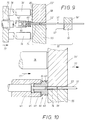
- the plunger is then transferred to the second rotary position 40 'shown in dash-dotted lines in FIG. 2 and thereby assumes the working positions shown in FIGS. 9 to 12 relative to the section of the line 51 positioned by the line holder 50.
- the plunger 40 ' is axially aligned with the line end 52.
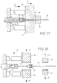
- the line holder 50 consists of two components 55, 56 which are arranged at an axial distance 57 from one another and which have different functions to perform. These consist of pairs of jaws which act in the manner of tongs, namely clamping jaws 56, 56 'and sliding jaws 55, 55'.
- the line end 52 can, if necessary, be provided with a circumferential notch 58 in its insulation jacket.
- the insulation end piece 74 separated from the notch 58 initially remains on the line end 52 during handling in the device according to the invention, but is later removed before the contact member is connected.
- a sensor 80 is provided which checks whether a sealing plug 60 has been picked properly or not. The simplest is the sensor 80 from a light barrier indicated in Fig. 2 and 9, the z. B. is arranged shortly before the starting position shown in FIG. 9 of the two sliding jaws 55, 55 '.
- the device has, as shown in FIG. 1, a second, horizontally active thrust drive 75, on which there are two push rods 76, 76 'which, as shown in FIG. 9, hold the plunger in the second rotational position 40' between them and are aligned with the two jaws 55, 55 '.
- the push rods 76, 76 ' finally meet the two sliding jaws 55, 55' folded together, as shown in FIG. 10, and take them from there in the direction of the arrow 77 there With.
- the tappet sleeve 46 is provided with a stop 78 against which the thrust drive 75 abuts and consequently takes the tappet sleeve 46 in the pushing direction 77.
- the plunger pin 45 is only carried a small distance axially up to the working position shown in FIG. 10. Because of the abutment of the sleeve end face 49 on the shoulder surface 64 which has already been mentioned and is particularly clear in FIG. 10, the sealing plug 60 is increasingly stripped off by the tappet pin 45. For this reason, as already mentioned at the beginning, this second rotational position 40 'of the tappet is briefly referred to below as the “stripping position”.
- both the sliding jaws 55, 55' and the clamping jaws 56, 56 ' open in the sense of the spreading movement arrows 79, 79' shown in FIG. 12.
- the line 51 properly fitted with the sealing ring 60 is still held by the above-mentioned feed device 54 and can be moved further in the sense of the transport arrow 53 already mentioned will.
- the plunger initially remaining in its stripping position 40' but also the two sliding jaws 55, 55 'reach their starting position as shown in FIG. 9.
- the work cycle is now complete.
- the plunger is now pivoted again about its pivot bearing 42 and arrives in the pick-up position 40 shown in FIGS. 2 and 6 relative to the slide 30, which is now transferred to its second thrust end position mentioned above.
- the sealing plug 60 located in the first edge recess 31 thus reaches the center of the push path 34 and is ready for picking 44 in analogy to FIGS. 6 and 7 during the next working cycle.
- the feed device 54 brings the line 51 equipped with the sealing plug 60 to a position where the aforementioned insulation end piece 74 can be pulled off the conductor 51 in front of the ring notch 58.
- the feed device 54 then transports the line 51 to a device where the contact element already mentioned several times can be crimped on the line end 52 behind the end flange 73 of FIG. 1 a.
Landscapes
- Engineering & Computer Science (AREA)
- Manufacturing & Machinery (AREA)
- Sealing Of Jars (AREA)
- Connector Housings Or Holding Contact Members (AREA)
- Manufacturing Of Electrical Connectors (AREA)
Applications Claiming Priority (2)
| Application Number | Priority Date | Filing Date | Title |
|---|---|---|---|
| DE4131051A DE4131051C1 (fr) | 1991-09-18 | 1991-09-18 | |
| DE4131051 | 1991-09-18 |
Publications (3)
| Publication Number | Publication Date |
|---|---|
| EP0533045A2 true EP0533045A2 (fr) | 1993-03-24 |
| EP0533045A3 EP0533045A3 (en) | 1993-07-21 |
| EP0533045B1 EP0533045B1 (fr) | 1995-06-28 |
Family
ID=6440898
Family Applications (1)
| Application Number | Title | Priority Date | Filing Date |
|---|---|---|---|
| EP92115402A Expired - Lifetime EP0533045B1 (fr) | 1991-09-18 | 1992-09-09 | Dispositif pour faire glisser mécaniquement des bouchons élastiques d'étanchéité sur câbles électriques |
Country Status (4)
| Country | Link |
|---|---|
| EP (1) | EP0533045B1 (fr) |
| AT (1) | ATE124578T1 (fr) |
| DE (2) | DE4131051C1 (fr) |
| ES (1) | ES2075556T3 (fr) |
Cited By (7)
| Publication number | Priority date | Publication date | Assignee | Title |
|---|---|---|---|---|
| EP0661780A1 (fr) * | 1993-12-28 | 1995-07-05 | Sumitomo Wiring Systems, Ltd. | Méthode et dispositif d'alimentation de pièces |
| EP0875966A1 (fr) * | 1997-04-29 | 1998-11-04 | Sumitomo Wiring Systems, Ltd. | Procédé et dispositif pour l'introduction des câbles dans ou au travers d'une partie |
| WO2011158145A1 (fr) * | 2010-06-16 | 2011-12-22 | Schleuniger Holding Ag | Dispositif destiné à mettre en place des passe-câbles sur un câble |
| ITPD20120392A1 (it) * | 2012-12-20 | 2014-06-21 | Wirmec Srl | Macchina per il fissaggio di elementi elastici su cavi elettrici |
| US9352430B2 (en) | 2010-06-16 | 2016-05-31 | Schleuniger Holding Ag | Cable grommet fitting apparatus for cable |
| US9649737B2 (en) | 2012-09-12 | 2017-05-16 | Schleuniger Holding Ag | Machines and processes for fitting cable bushings |
| US9653865B2 (en) | 2011-09-29 | 2017-05-16 | Schleuniger Holding Ag | Method for fitting cables with cable sleeves |
Families Citing this family (1)
| Publication number | Priority date | Publication date | Assignee | Title |
|---|---|---|---|---|
| DE102009026006B4 (de) * | 2009-06-19 | 2013-11-21 | Rennsteig Werkzeuge Gmbh | Vorrichtung zum Aufziehen und Positionieren einer Tülle auf ein Kabel |
Family Cites Families (3)
| Publication number | Priority date | Publication date | Assignee | Title |
|---|---|---|---|---|
| DE3347424A1 (de) * | 1982-12-31 | 1984-07-05 | Meier, geb.Konnerth, Elinore, 7763 Öhningen | Vorrichtung mit wenigstens einer rinne oder nut zum zufuehren kleiner maschinenelemente zu einer station |
| US4653182A (en) * | 1984-04-17 | 1987-03-31 | Sumitomo Electric Industries, Ltd. | Apparatus for fitting terminals and rubber stoppers on wires |
| DE8909515U1 (de) * | 1989-08-08 | 1990-12-06 | Grote & Hartmann Gmbh & Co Kg, 42369 Wuppertal | Vorrichtung zum maschinellen Aufbringen von Dichtungsstopfen auf elektrische Leitungen |
-
1991
- 1991-09-18 DE DE4131051A patent/DE4131051C1/de not_active Expired - Fee Related
-
1992
- 1992-09-09 DE DE59202696T patent/DE59202696D1/de not_active Expired - Fee Related
- 1992-09-09 AT AT92115402T patent/ATE124578T1/de active
- 1992-09-09 ES ES92115402T patent/ES2075556T3/es not_active Expired - Lifetime
- 1992-09-09 EP EP92115402A patent/EP0533045B1/fr not_active Expired - Lifetime
Cited By (15)
| Publication number | Priority date | Publication date | Assignee | Title |
|---|---|---|---|---|
| EP0661780A1 (fr) * | 1993-12-28 | 1995-07-05 | Sumitomo Wiring Systems, Ltd. | Méthode et dispositif d'alimentation de pièces |
| EP0875966A1 (fr) * | 1997-04-29 | 1998-11-04 | Sumitomo Wiring Systems, Ltd. | Procédé et dispositif pour l'introduction des câbles dans ou au travers d'une partie |
| US5901438A (en) * | 1997-04-29 | 1999-05-11 | Sumitomo Wiring Systems, Ltd. | Apparatus and method for introducing cables into or through a part |
| US9496076B2 (en) | 2010-06-16 | 2016-11-15 | Schleuniger Holding Ag | Cable grommet fitting apparatus for cable |
| CN102918724A (zh) * | 2010-06-16 | 2013-02-06 | 施洛伊尼格控股有限公司 | 用于将缆线扣眼安装到缆线上的设备 |
| JP2013531963A (ja) * | 2010-06-16 | 2013-08-08 | シュロニガー ホールディング アーゲー | ケーブルスリーブをケーブル上にフィッティングするための器械 |
| CN102918724B (zh) * | 2010-06-16 | 2016-01-20 | 施洛伊尼格控股有限公司 | 用于将缆线扣眼安装到缆线上的设备 |
| US9352430B2 (en) | 2010-06-16 | 2016-05-31 | Schleuniger Holding Ag | Cable grommet fitting apparatus for cable |
| WO2011158145A1 (fr) * | 2010-06-16 | 2011-12-22 | Schleuniger Holding Ag | Dispositif destiné à mettre en place des passe-câbles sur un câble |
| US9653865B2 (en) | 2011-09-29 | 2017-05-16 | Schleuniger Holding Ag | Method for fitting cables with cable sleeves |
| US10348031B2 (en) | 2011-09-29 | 2019-07-09 | Schleuniger Holding Ag | Apparatus for fitting cables with cable sleeves |
| US9649737B2 (en) | 2012-09-12 | 2017-05-16 | Schleuniger Holding Ag | Machines and processes for fitting cable bushings |
| US10427267B2 (en) | 2012-09-12 | 2019-10-01 | Schleuniger Holding Ag | Machine and processes for fitting cable bushings |
| US10814450B2 (en) | 2012-09-12 | 2020-10-27 | Schleuniger Holding Ag | Processes for fitting cable bushings |
| ITPD20120392A1 (it) * | 2012-12-20 | 2014-06-21 | Wirmec Srl | Macchina per il fissaggio di elementi elastici su cavi elettrici |
Also Published As
| Publication number | Publication date |
|---|---|
| ES2075556T3 (es) | 1995-10-01 |
| ATE124578T1 (de) | 1995-07-15 |
| EP0533045A3 (en) | 1993-07-21 |
| DE59202696D1 (de) | 1995-08-03 |
| EP0533045B1 (fr) | 1995-06-28 |
| DE4131051C1 (fr) | 1993-03-04 |
Similar Documents
| Publication | Publication Date | Title |
|---|---|---|
| DE3404460C2 (de) | Vorrichtung und Verfahren zur Förderung von Teilen | |
| DE60105549T2 (de) | Vorrichtung zum repositionieren von produkten während beibehaltung der vorwärtsgeschwindigkeit | |
| EP0054775B1 (fr) | Dispositif de tri de bobines coniques | |
| DE68912136T2 (de) | Selbsttätige sortierungsvorrichtung für gegenstände. | |
| WO1999001295A1 (fr) | Poste de manipulation, notamment dispositif a mettre sous enveloppe | |
| DE69411421T2 (de) | Vorrichtung in Kombination mit und zur Orientierung von Körper und Kappe von Hartgelatine-Kapseln | |
| DE69302603T2 (de) | Vorrichtung zum selektiven Weiterbefördern von Produktreihen auf dem einen oder dem anderen Förderer von Paaren von Bandfördern | |
| EP0709316A1 (fr) | Dispositif de transfert de rangées transversales d'objets alimentés d'une bande convoyeuse sans fin | |
| DE3643201A1 (de) | Verfahren und vorrichtung zum ablaengen von kabeln von einem kabelvorrat zur bearbeitung der kabelenden | |
| EP0533045B1 (fr) | Dispositif pour faire glisser mécaniquement des bouchons élastiques d'étanchéité sur câbles électriques | |
| DE3528743A1 (de) | Materialstangenzufuehrvorrichtung | |
| DD156244A5 (de) | Verpackungsmaschine fuer suessigkeiten,insbesondere bonbons | |
| DE2603165C3 (de) | Vorrichtung zum Transportieren von Wälzlagerringen | |
| DE2742622A1 (de) | Entnahmevorrichtung | |
| DE8900172U1 (de) | Hängefördereinrichtung | |
| DE1654871B2 (de) | Vorrichtung zum ausrichten von fischen | |
| DE3714108A1 (de) | Vorrichtung zur uebergabe von werkstuecktraegern | |
| DE3825273C2 (de) | Spulentransporteinrichtung mit auskragendem Dorn | |
| CH666880A5 (de) | Huelsenuebergabevorrichtung. | |
| EP0328876B1 (fr) | Dispositif pour ouvrir des douilles plates | |
| WO2002024556A1 (fr) | Procede et dispositif d'apport d'objets reguliers a une station de travail | |
| DE4400943A1 (de) | Vorrichtung zum Anordnen, Füllen und Verschweißen von Hülsen für die künstliche Besamung | |
| DE3919525C2 (de) | Maschinenverbund zwischen Spinn- und Spulmaschinen | |
| DE3631718A1 (de) | Ladeeinrichtung mit ladekreuz | |
| EP0786425A2 (fr) | Dispositif de transfert d'objet arrivant en rangées transversales ou groupés vers une bande d'évacuation |
Legal Events
| Date | Code | Title | Description |
|---|---|---|---|
| PUAI | Public reference made under article 153(3) epc to a published international application that has entered the european phase |
Free format text: ORIGINAL CODE: 0009012 |
|
| AK | Designated contracting states |
Kind code of ref document: A2 Designated state(s): AT BE DE ES FR GB IT PT SE |
|
| PUAL | Search report despatched |
Free format text: ORIGINAL CODE: 0009013 |
|
| AK | Designated contracting states |
Kind code of ref document: A3 Designated state(s): AT BE DE ES FR GB IT PT SE |
|
| 17P | Request for examination filed |
Effective date: 19930616 |
|
| 17Q | First examination report despatched |
Effective date: 19941214 |
|
| GRAA | (expected) grant |
Free format text: ORIGINAL CODE: 0009210 |
|
| AK | Designated contracting states |
Kind code of ref document: B1 Designated state(s): AT BE DE ES FR GB IT PT SE |
|
| PG25 | Lapsed in a contracting state [announced via postgrant information from national office to epo] |
Ref country code: BE Effective date: 19950628 |
|
| REF | Corresponds to: |
Ref document number: 124578 Country of ref document: AT Date of ref document: 19950715 Kind code of ref document: T |
|
| ITF | It: translation for a ep patent filed | ||
| REF | Corresponds to: |
Ref document number: 59202696 Country of ref document: DE Date of ref document: 19950803 |
|
| GBT | Gb: translation of ep patent filed (gb section 77(6)(a)/1977) |
Effective date: 19950713 |
|
| PG25 | Lapsed in a contracting state [announced via postgrant information from national office to epo] |
Ref country code: AT Effective date: 19950909 |
|
| PG25 | Lapsed in a contracting state [announced via postgrant information from national office to epo] |
Ref country code: SE Effective date: 19950928 Ref country code: PT Effective date: 19950928 |
|
| REG | Reference to a national code |
Ref country code: ES Ref legal event code: FG2A Ref document number: 2075556 Country of ref document: ES Kind code of ref document: T3 |
|
| ET | Fr: translation filed | ||
| RAP2 | Party data changed (patent owner data changed or rights of a patent transferred) |
Owner name: DELPHI AUTOMOTIVE SYSTEMS DEUTSCHLAND GMBH |
|
| REG | Reference to a national code |
Ref country code: FR Ref legal event code: CD |
|
| PLBE | No opposition filed within time limit |
Free format text: ORIGINAL CODE: 0009261 |
|
| 26N | No opposition filed | ||
| REG | Reference to a national code |
Ref country code: GB Ref legal event code: IF02 |
|
| PGFP | Annual fee paid to national office [announced via postgrant information from national office to epo] |
Ref country code: GB Payment date: 20020902 Year of fee payment: 11 |
|
| PG25 | Lapsed in a contracting state [announced via postgrant information from national office to epo] |
Ref country code: GB Free format text: LAPSE BECAUSE OF NON-PAYMENT OF DUE FEES Effective date: 20030909 |
|
| PGFP | Annual fee paid to national office [announced via postgrant information from national office to epo] |
Ref country code: FR Payment date: 20030916 Year of fee payment: 12 |
|
| PGFP | Annual fee paid to national office [announced via postgrant information from national office to epo] |
Ref country code: ES Payment date: 20030929 Year of fee payment: 12 |
|
| PGFP | Annual fee paid to national office [announced via postgrant information from national office to epo] |
Ref country code: DE Payment date: 20031016 Year of fee payment: 12 |
|
| GBPC | Gb: european patent ceased through non-payment of renewal fee |
Effective date: 20030909 |
|
| PG25 | Lapsed in a contracting state [announced via postgrant information from national office to epo] |
Ref country code: ES Free format text: LAPSE BECAUSE OF NON-PAYMENT OF DUE FEES Effective date: 20040910 |
|
| PG25 | Lapsed in a contracting state [announced via postgrant information from national office to epo] |
Ref country code: DE Free format text: LAPSE BECAUSE OF NON-PAYMENT OF DUE FEES Effective date: 20050401 |
|
| PG25 | Lapsed in a contracting state [announced via postgrant information from national office to epo] |
Ref country code: FR Free format text: LAPSE BECAUSE OF NON-PAYMENT OF DUE FEES Effective date: 20050531 |
|
| REG | Reference to a national code |
Ref country code: FR Ref legal event code: ST |
|
| PG25 | Lapsed in a contracting state [announced via postgrant information from national office to epo] |
Ref country code: IT Free format text: LAPSE BECAUSE OF NON-PAYMENT OF DUE FEES;WARNING: LAPSES OF ITALIAN PATENTS WITH EFFECTIVE DATE BEFORE 2007 MAY HAVE OCCURRED AT ANY TIME BEFORE 2007. THE CORRECT EFFECTIVE DATE MAY BE DIFFERENT FROM THE ONE RECORDED. Effective date: 20050909 |
|
| REG | Reference to a national code |
Ref country code: ES Ref legal event code: FD2A Effective date: 20040910 |