EP0533086A2 - Fadenführervorrichtung für Rundstrickmaschinen, insbesondere für Streifenanlagen an Doppel-Zylindermaschinen für die Herstellung von Socken und Strümpfen - Google Patents
Fadenführervorrichtung für Rundstrickmaschinen, insbesondere für Streifenanlagen an Doppel-Zylindermaschinen für die Herstellung von Socken und Strümpfen Download PDFInfo
- Publication number
- EP0533086A2 EP0533086A2 EP92115683A EP92115683A EP0533086A2 EP 0533086 A2 EP0533086 A2 EP 0533086A2 EP 92115683 A EP92115683 A EP 92115683A EP 92115683 A EP92115683 A EP 92115683A EP 0533086 A2 EP0533086 A2 EP 0533086A2
- Authority
- EP
- European Patent Office
- Prior art keywords
- thread guide
- thread
- guide body
- respect
- oscillation
- Prior art date
- Legal status (The legal status is an assumption and is not a legal conclusion. Google has not performed a legal analysis and makes no representation as to the accuracy of the status listed.)
- Withdrawn
Links
Images

Classifications
-
- D—TEXTILES; PAPER
- D04—BRAIDING; LACE-MAKING; KNITTING; TRIMMINGS; NON-WOVEN FABRICS
- D04B—KNITTING
- D04B15/00—Details of, or auxiliary devices incorporated in, weft knitting machines, restricted to machines of this kind
- D04B15/38—Devices for supplying, feeding, or guiding threads to needles
- D04B15/54—Thread guides
- D04B15/58—Thread guides for circular knitting machines; Thread-changing devices
Definitions
- the present invention relates to a thread guide structure for circular knitting machines, in particular for line-forming units in double-cylinder machines for manufacturing socks and stockings.
- each thread guide can be actuated individually in order to pass from an inactive position, wherein its thread dispensing end is spaced from the needle cylinders so as to prevent the needles from engaging the thread, to an active position, wherein the thread dispensing end is moved closer to the needle cylinders in order to allow the correct feeding of the thread to the needles.
- line-forming units By means of line-forming units it is possible to feed, to a same feed of the machine, threads having different colors, counts and components, so as to meet the various production requirements.
- each thread guide from the inactive position to the active position is obtained with various types of actuation device which cause an oscillation of the thread guide about an axis which is parallel to the axis of the needle cylinders and subsequently a translatory motion of the thread guide toward the needle cylinders.
- the thread guide which is subsequently actuated must pass over a thread guide which has been actuated previously and is thus already in the active position.
- the line-forming unit is provided, on the opposite side with respect to the needle cylinders, with a plate in which an appropriate path is defined; the thread guide engages said path so that, in moving from the inactive position to the active position, or vice versa, it follows said path and thus does not interfere with any thread guide which might be already in the active position.
- the use of plates in which thread guide paths are defined complicates the manufacture of the line-forming units and the calibration of the thread guides. Furthermore, precision in the actuation of the thread guides decreases in the course of time due to the unavoidable wear of said plates.
- the aim of the present invention is to solve the problems described above by providing a thread guide with such a structure as to require no guides in order to pass over any other thread guides which are already active in a same line-forming unit or, more generally, obstacles located along the path which it must follow in order to move from the inactive position to the active position or vice versa.
- an object of the invention is to provide a thread guide with such a structure as to considerably simplify the manufacture and calibration of line-forming units in knitting machines.
- Another object of the invention is to provide a thread guide with good operating precision.
- a further object of the invention is to provide a thread guide which has competitive production costs.
- a thread guide structure for circular knitting machines in particular for line-forming units in double-cylinder circular knitting machines for manufacturing socks and stockings
- a thread guide body having an elongated configuration and, proximate to one of its longitudinal ends, a thread dispensing passage
- said thread guide body is constituted at least by one first part and by one second part which are mutually articulated proximate to an intermediate region of the thread guide body, said first part being provided with said thread dispensing passage and being oscillatable with respect to said second part about an oscillation axis arranged transversely to the longitudinal extension of said thread guide body.
- the thread guide having the structure according to the invention, generally designated by the reference numeral 1, comprises a thread guide body 2 which is substantially rod-like and has, at one of its longitudinal ends, a passage 3 for dispensing the thread 40.
- the body 2 is constituted by at least one first part 4 and by at least one second part 5 which are mutually articulated proximate to an intermediate region of the thread guide body.
- the first part 4, which is provided with the dispensing passage 3, can oscillate with respect to the second part 5 about an oscillation axis 6a which is arranged transversely to the longitudinal extension of the thread guide body 2.
- the first part 4 is substantially C-shaped proximate to the second part 5, with two opposite wings 7a and 7b between which a portion of the second part 5 is inserted.
- the wings 7a and 7b of the first part 4 are associated, so as to be able to rotate, with the second part 5 by means of a pivot 6 which defines the oscillation axis 6a.
- the portion of the second part 5 which is arranged between the wings 7a and 7b extends along the first part 4 beyond the pivot 6 so as to define a supporting region 8 for a stop abutment 9 provided in the first part 4 so as to delimit the oscillation arc, in one direction, of the first part 4 with respect to the second part 5.
- the oscillation arc of the first part 4 with respect to the second part 5 in the opposite direction is delimited by a spring 10 which rests against the lower side of the first part 4 and is accommodated in an appropriate seat 11 defined in the back of the second part 5.
- the spring 10 is arranged, with respect to the pivot 6, on the opposite side with respect to the stop abutment 9 so as to act as elastic return means which contrasts the oscillation of the first part 4 with respect to the second part 5.
- the first part 4 can oscillate with respect to the second part 5 about the oscillation axis 6a from a first position, wherein the first part 4 is substantially aligned with the second part 5, to a second position, wherein the first part 4 is inclined with respect to the second part 5, and the oscillation of the first part 4 in order to move from the first position to the second position is elastically contrasted by the spring 10.
- the first part 4 is manufactured in two pieces which are mutually associated by means of a coupling constituted by a male thread 12 and a female thread 13 whose axis is parallel to the longitudinal axis of the thread guide body, so as to allow to calibrate the useful length of the thread guide.
- the thread guide body 2 is mounted on a supporting element 14 which is associated, by means of a pivot 15, with a supporting block 16 so as to be oscillatable, with respect to the supporting block 16, about the axis 15a of the pivot 15.
- the axis 15a is arranged transversely to the longitudinal extension of the thread guide and is perpendicular to the axis 6a of the pivot 6 so that the thread guide can oscillate, together with the supporting element 14, about the axis 15a in a plane and so that the first part 4 can oscillate, with respect to the second part 5, about the axis 6a in a plane which is perpendicular to the plane of oscillation of the thread guide as a whole.
- the thread guide body 2 is furthermore coupled to the supporting element 14 so as to be slidable along a direction which is parallel to its longitudinal extension.
- the first part 5 is coupled, so as to be longitudinally slidable, within a seat 17 defined in the supporting element 14.
- a slot 18 is defined in the second part 5 and is elongated along a direction which is parallel to the longitudinal extension of the thread guide; said slot is crossed by the pivot 15 which, in this manner, delimits the length of the sliding of the thread guide body with respect to the supporting element 14.
- the thread guide body slides toward its thread dispensing end against the biasing action of a spring 19 which is inserted in an appropriate seat 20 defined in the supporting element 14 and acts with one of its ends against a shoulder 21 of the second part 5.
- the thread guide according to the invention can be actuated with known actuation means, for example fluid-activated cylinders, electromagnetic actuators, cams, which act on the thread guide body 2 and/or on the supporting element 14 so as to cause the oscillation of the thread guide about the axis 15a and the sliding of the thread guide body parallel to its longitudinal extension with respect to the supporting element 14.
- known actuation means for example fluid-activated cylinders, electromagnetic actuators, cams, which act on the thread guide body 2 and/or on the supporting element 14 so as to cause the oscillation of the thread guide about the axis 15a and the sliding of the thread guide body parallel to its longitudinal extension with respect to the supporting element 14.
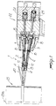
- figure 1 shows a line-forming unit, generally designated by the reference numeral 22, which is equipped with two thread guides 1 according to the invention and laterally faces the needle cylinders 23 of a double-cylinder circular knitting machine.
- the thread guide according to the invention is arranged so that its axis 15a is substantially parallel to the axis 23a of the needle cylinders 23 or slightly inclined so as to cause the thread dispensing ends of a plurality of thread guides to converge in the direction of the needle cylinders.
- each thread guide of the line-forming unit oscillates, for example by virtue of the action of known actuation means, in a plane which is substantially perpendicular or inclined with respect to the axis 23a, and the thread guide body is moved longitudinally in order to move its end for delivering the thread 40 closer to the needle cylinders.
- figure 1 shows, merely by way of example, two fluid-activated actuators 24 and 25 for the actuation of the thread guides.
- the actuation of the thread guide according to the invention could also be obtained with electromagnetic actuators, cams, etc.
- the thread guide 1 is caused to oscillate about the axis 15a and subsequently the thread guide body 2 is moved longitudinally.
- the first part 4 of the thread guide encounters a thread guide which is already active during this movement, the impact against said thread guide causes the oscillation of the first part 4 with respect to the second part 5.
- the first part 4 of the thread guide which is actuated subsequently can surmount the previously actuated thread guide or in any case rest above it or below it, according to requirements.
- the surmounting action can occur by virtue of the oscillation of the first part 4 of the subsequently actuated thread guide or due to the oscillation of the first part 4 of the previously actuated thread guide.
- the thread guide according to the invention fully achieves the intended aim, since by virtue of the fact that its body is manufactured in two mutually articulated parts, it can surmount other thread guides which are already active, or obstacles in general, without requiring the use of any guide.
- the thread guide thus conceived is susceptible to numerous modifications and variations, all of which are within the scope of the inventive concept; thus, for example, the first part 4 can be articulated to the second part 5 so as to be oscillatable in the direction opposite to the one shown; furthermore, all the details may be replaced with technically equivalent elements.
- the materials employed, as well as the dimensions, may be any according to the requirements and the state of the art.
Landscapes
- Engineering & Computer Science (AREA)
- Textile Engineering (AREA)
- Knitting Machines (AREA)
Applications Claiming Priority (2)
| Application Number | Priority Date | Filing Date | Title |
|---|---|---|---|
| ITMI912476A IT1251329B (it) | 1991-09-19 | 1991-09-19 | Struttura di guidafilo per macchine circolari per maglieria, in particolare per gruppi rigatori in macchine per calze a doppio cilindro |
| ITMI912476 | 1991-09-19 |
Publications (2)
| Publication Number | Publication Date |
|---|---|
| EP0533086A2 true EP0533086A2 (de) | 1993-03-24 |
| EP0533086A3 EP0533086A3 (en) | 1993-04-21 |
Family
ID=11360703
Family Applications (1)
| Application Number | Title | Priority Date | Filing Date |
|---|---|---|---|
| EP19920115683 Withdrawn EP0533086A3 (en) | 1991-09-19 | 1992-09-14 | Thread guide structure for circular knitting machines, in particular for line-forming units in double-cylinder machines for manufacturing socks and stockings |
Country Status (5)
| Country | Link |
|---|---|
| US (1) | US5251463A (de) |
| EP (1) | EP0533086A3 (de) |
| JP (1) | JPH05195387A (de) |
| CZ (1) | CZ286392A3 (de) |
| IT (1) | IT1251329B (de) |
Cited By (3)
| Publication number | Priority date | Publication date | Assignee | Title |
|---|---|---|---|---|
| EP0683258A1 (de) * | 1994-05-16 | 1995-11-22 | MATEC S.r.l. | Aufprallschutzvorrichtung für eine Stange zur Positionierung von den Fadenführern an einer Rundstrickmaschine |
| CN101994207A (zh) * | 2010-12-07 | 2011-03-30 | 宁波裕人数控科技有限公司 | 电脑丝袜机喂纱装置 |
| US20160130735A1 (en) * | 2013-06-21 | 2016-05-12 | Santoni S.P.A. | Device for feeding thread to needles of a knitting machine |
Families Citing this family (7)
| Publication number | Priority date | Publication date | Assignee | Title |
|---|---|---|---|---|
| JP3667485B2 (ja) * | 1997-02-19 | 2005-07-06 | 株式会社福原精機製作所 | 丸編機における給糸切換方法 |
| CZ301577B6 (cs) * | 2003-04-15 | 2010-04-21 | UNIPLET TREBÍC, a.s. | Zpusob ovládání elastické nite a zarízení k provádení zpusobu |
| KR100893563B1 (ko) * | 2007-05-25 | 2009-04-17 | (주) 태영기계 | 편직기용 사도 및 이를 구비하는 양말편직기 |
| IT201700057890A1 (it) * | 2017-05-29 | 2018-11-29 | Lonati Spa | Dispositivo di alimentazione del filo o dei fili per maglieria o per calzetteria. |
| US10669658B2 (en) * | 2017-12-06 | 2020-06-02 | Pai Lung Machinery Mill Co., Ltd. | Electronic yarn changing device for circular knitting machine |
| TWD208383S (zh) * | 2019-06-18 | 2020-11-21 | 義大利商聖東尼股份公司 | 紡織機構件 |
| TWD208197S (zh) * | 2019-06-18 | 2020-11-11 | 義大利商聖東尼股份公司 | 紡織機構件 |
Family Cites Families (10)
| Publication number | Priority date | Publication date | Assignee | Title |
|---|---|---|---|---|
| GB542526A (de) * | 1900-01-01 | |||
| US2885874A (en) * | 1954-03-01 | 1959-05-12 | Zapadomoravske Strojirny | Apparatus for feeding and changing of yarns in circular knitting machines |
| FR1102631A (fr) * | 1954-04-09 | 1955-10-24 | Gaston Verdier Ets | Perfectionnement aux jeteurs de fil pour métiers rectilignes de bonneterie |
| US3331220A (en) * | 1965-04-26 | 1967-07-18 | Singer Co | Yarn trimming mechanisms |
| US3555855A (en) * | 1968-09-18 | 1971-01-19 | Billi Spa | Circular knitting machine |
| CH552699A (fr) * | 1972-08-30 | 1974-08-15 | Dubied & Cie Sa E | Guide-fil pour une machine a tricoter rectiligne, muni d'un bec-fil en ceramique. |
| IT8021362V0 (it) * | 1980-04-01 | 1980-04-01 | Lonati Cost Mecc | Gruppo di alimentazione perfezionato in una macchina circolare per maglieria monocilindrica, in particolare una macchina per calze o simili |
| CS252906B1 (en) * | 1984-03-13 | 1987-10-15 | Milan Fucik | Striping device for double-cylinder circular knitting frame |
| ES2006232A6 (es) * | 1987-12-04 | 1989-04-16 | Jumberca Sa | Sistema para listar en una maquina circular de genero de punto. |
| JP2761926B2 (ja) * | 1989-07-05 | 1998-06-04 | 株式会社福原精機製作所 | 丸編機における給糸切換装置 |
-
1991
- 1991-09-19 IT ITMI912476A patent/IT1251329B/it active IP Right Grant
-
1992
- 1992-09-14 JP JP4244352A patent/JPH05195387A/ja active Pending
- 1992-09-14 US US07/944,763 patent/US5251463A/en not_active Expired - Fee Related
- 1992-09-14 EP EP19920115683 patent/EP0533086A3/en not_active Withdrawn
- 1992-09-17 CZ CS922863A patent/CZ286392A3/cs unknown
Cited By (4)
| Publication number | Priority date | Publication date | Assignee | Title |
|---|---|---|---|---|
| EP0683258A1 (de) * | 1994-05-16 | 1995-11-22 | MATEC S.r.l. | Aufprallschutzvorrichtung für eine Stange zur Positionierung von den Fadenführern an einer Rundstrickmaschine |
| US5491987A (en) * | 1994-05-16 | 1996-02-20 | Matec S.R.L. | Impact protection device for a rod for positioning thread guides in a circular knitting machine |
| CN101994207A (zh) * | 2010-12-07 | 2011-03-30 | 宁波裕人数控科技有限公司 | 电脑丝袜机喂纱装置 |
| US20160130735A1 (en) * | 2013-06-21 | 2016-05-12 | Santoni S.P.A. | Device for feeding thread to needles of a knitting machine |
Also Published As
| Publication number | Publication date |
|---|---|
| ITMI912476A0 (it) | 1991-09-19 |
| IT1251329B (it) | 1995-05-08 |
| JPH05195387A (ja) | 1993-08-03 |
| ITMI912476A1 (it) | 1993-03-19 |
| CZ286392A3 (en) | 1993-04-14 |
| EP0533086A3 (en) | 1993-04-21 |
| US5251463A (en) | 1993-10-12 |
Similar Documents
| Publication | Publication Date | Title |
|---|---|---|
| EP0533086A2 (de) | Fadenführervorrichtung für Rundstrickmaschinen, insbesondere für Streifenanlagen an Doppel-Zylindermaschinen für die Herstellung von Socken und Strümpfen | |
| US6988385B2 (en) | Yarn feeder of weft knitting machine and method of feeding yarn for weft knitting machine | |
| JP4480331B2 (ja) | 横編機のヤーンフィーダ | |
| KR20090031599A (ko) | 싱커 없이 래치 니들을 구비한 편물기 | |
| CN105714466A (zh) | 具有将纬纱、经纱和/或浮纱退圈和垫入的装置的横机 | |
| US20180282916A1 (en) | Plunger systems and multi-function feeders for a knitting machine | |
| US8387418B1 (en) | Yarn feeder for flat knitting machines | |
| US5237841A (en) | Thread feed unit using pneumatic actuators | |
| TWI591226B (zh) | 用於進送線至針織機之織針的裝置(二) | |
| US5491989A (en) | Yarn guide and yarn guide unit for a jacquard knitting machine | |
| ITMI20111696A1 (it) | Macchina per maglieria, particolarmente ad elevata finezza, con camme di azionamento degli aghi perfezionate. | |
| US4640103A (en) | Double head flat knitting machine | |
| US4838048A (en) | Knitting machine | |
| US2825214A (en) | Stop mechanism control means for knitting machines | |
| US7047769B2 (en) | Loop-forming system and sinker for such a system | |
| EP2570537A1 (de) | Fadenführer für eine Flachstrickmaschine | |
| CN100334279C (zh) | 用于圆型针织机的线圈松紧度改变装置 | |
| US1933408A (en) | Circular knitting machine | |
| GB2061327A (en) | A needle control and selection mechanism for a knitting | |
| US3318110A (en) | Flat bed knitting machines | |
| US2381376A (en) | Slur cam for knitting machines | |
| KR101804751B1 (ko) | 편물기용 바늘, 스티치 형성을 위한 장치, 및 편물기에서 상기 장치의 사용 | |
| CZ20014157A3 (cs) | Jehelní ovládací zařízení pro punčochový pletací stroj | |
| DE4431239A1 (de) | Flachstrickmaschine | |
| US3474642A (en) | Yarn guide control apparatus for a flat knitting machine having a multiple cam system |
Legal Events
| Date | Code | Title | Description |
|---|---|---|---|
| PUAI | Public reference made under article 153(3) epc to a published international application that has entered the european phase |
Free format text: ORIGINAL CODE: 0009012 |
|
| PUAL | Search report despatched |
Free format text: ORIGINAL CODE: 0009013 |
|
| AK | Designated contracting states |
Kind code of ref document: A2 Designated state(s): DE FR GB |
|
| AK | Designated contracting states |
Kind code of ref document: A3 Designated state(s): DE FR GB |
|
| 17P | Request for examination filed |
Effective date: 19930917 |
|
| RAP1 | Party data changed (applicant data changed or rights of an application transferred) |
Owner name: LONATI S.P.A. |
|
| 18W | Application withdrawn |
Withdrawal date: 19950725 |