EP0533112B1 - Verbesserte Lichtwellenleiter-Halterung und -Träger - Google Patents
Verbesserte Lichtwellenleiter-Halterung und -Träger Download PDFInfo
- Publication number
- EP0533112B1 EP0533112B1 EP92115773A EP92115773A EP0533112B1 EP 0533112 B1 EP0533112 B1 EP 0533112B1 EP 92115773 A EP92115773 A EP 92115773A EP 92115773 A EP92115773 A EP 92115773A EP 0533112 B1 EP0533112 B1 EP 0533112B1
- Authority
- EP
- European Patent Office
- Prior art keywords
- chamber
- optical fiber
- diode laser
- fiber
- connector
- Prior art date
- Legal status (The legal status is an assumption and is not a legal conclusion. Google has not performed a legal analysis and makes no representation as to the accuracy of the status listed.)
- Expired - Lifetime
Links
Images
Classifications
-
- H—ELECTRICITY
- H04—ELECTRIC COMMUNICATION TECHNIQUE
- H04N—PICTORIAL COMMUNICATION, e.g. TELEVISION
- H04N1/00—Scanning, transmission or reproduction of documents or the like, e.g. facsimile transmission; Details thereof
- H04N1/024—Details of scanning heads ; Means for illuminating the original
- H04N1/032—Details of scanning heads ; Means for illuminating the original for picture information reproduction
- H04N1/036—Details of scanning heads ; Means for illuminating the original for picture information reproduction for optical reproduction
-
- G—PHYSICS
- G02—OPTICS
- G02B—OPTICAL ELEMENTS, SYSTEMS OR APPARATUS
- G02B6/00—Light guides; Structural details of arrangements comprising light guides and other optical elements, e.g. couplings
- G02B6/24—Coupling light guides
- G02B6/42—Coupling light guides with opto-electronic elements
- G02B6/4201—Packages, e.g. shape, construction, internal or external details
- G02B6/4285—Optical modules characterised by a connectorised pigtail
-
- G—PHYSICS
- G02—OPTICS
- G02B—OPTICAL ELEMENTS, SYSTEMS OR APPARATUS
- G02B6/00—Light guides; Structural details of arrangements comprising light guides and other optical elements, e.g. couplings
- G02B6/44—Mechanical structures for providing tensile strength and external protection for fibres, e.g. optical transmission cables
- G02B6/4439—Auxiliary devices
- G02B6/444—Systems or boxes with surplus lengths
- G02B6/4452—Distribution frames
- G02B6/44524—Distribution frames with frame parts or auxiliary devices mounted on the frame and collectively not covering a whole width of the frame or rack
-
- G—PHYSICS
- G02—OPTICS
- G02B—OPTICAL ELEMENTS, SYSTEMS OR APPARATUS
- G02B6/00—Light guides; Structural details of arrangements comprising light guides and other optical elements, e.g. couplings
- G02B6/44—Mechanical structures for providing tensile strength and external protection for fibres, e.g. optical transmission cables
- G02B6/4439—Auxiliary devices
- G02B6/444—Systems or boxes with surplus lengths
- G02B6/44528—Patch-cords; Connector arrangements in the system or in the box
-
- G—PHYSICS
- G02—OPTICS
- G02B—OPTICAL ELEMENTS, SYSTEMS OR APPARATUS
- G02B6/00—Light guides; Structural details of arrangements comprising light guides and other optical elements, e.g. couplings
- G02B6/24—Coupling light guides
- G02B6/42—Coupling light guides with opto-electronic elements
- G02B6/4201—Packages, e.g. shape, construction, internal or external details
- G02B6/4219—Mechanical fixtures for holding or positioning the elements relative to each other in the couplings; Alignment methods for the elements, e.g. measuring or observing methods especially used therefor
- G02B6/4236—Fixing or mounting methods of the aligned elements
- G02B6/4245—Mounting of the opto-electronic elements
-
- G—PHYSICS
- G02—OPTICS
- G02B—OPTICAL ELEMENTS, SYSTEMS OR APPARATUS
- G02B6/00—Light guides; Structural details of arrangements comprising light guides and other optical elements, e.g. couplings
- G02B6/24—Coupling light guides
- G02B6/42—Coupling light guides with opto-electronic elements
- G02B6/4201—Packages, e.g. shape, construction, internal or external details
- G02B6/4266—Thermal aspects, temperature control or temperature monitoring
- G02B6/4268—Cooling
- G02B6/4269—Cooling with heat sinks or radiation fins
Definitions
- the present invention relates to an optical fiber and laser mount useful in a color proofing apparatus which utilizes an electronic signal input, and more particularly, to a method and apparatus for automatically producing full-color proof images using lasers to provide thermal energy to a series of color dye-donors to selectively transfer each dye in registration to a receiver to form a proof image.
- Color-proofing is the procedure used by the printing industry for creating representative images that replicate the appearance of printed images without the cost and time required to actually set up a high-speed, high-volume printing press to print an example of the images intended.
- these representative images, or proofs have been generated from the same color-separations used to produce the individual color printing plates used in printing presses so that variations in the resulting images can be minimized.
- Various color-proofing systems have been devised to create the proofs and have included the use of smaller, slower presses as well as means other than presses, such as photographic, electrophotographic, and non-photographic processes.
- the proofs generated are judged for composition, screening, resolution, color, editing, and other visual content.
- Other considerations used in judging proofing systems include reproducibility, cost of the system as well as cost of the individual proofs, speed, and freedom from environmental problems. Further, since nearly all printing presses utilize the half-tone process for forming pictorial images, wherein the original image is screened, i. e.
- proofing processes that employ the half-tone process to form the proof image have been better accepted by the printing industry than have continuous tone systems.
- Electrophotographic proofing systems with half-tone capability have been introduced which employ either wet or dry processes.
- the electrophotographic systems that use dry processes suffer from the lack of high resolution necessary for better quality proofing, particularly when the images are of almost continuous tone quality. This results from the fact that dry electrophotographic processes do not employ toner particles which have a sufficiently small size to provide the requisite high image resolution. While wet electrophotographic processes do employ toners with the requisite small particle size, they have other disadvantages such as the use of solvents that are environmentally undesirable.
- a direct digital color proofer utilizing a thermal printer must be capable of consistently and accurately writing minipixels at a rate of 1800 dots per inch (dpi) and higher to generate half-tone proofs having a resolution of 150 lines per inch and above, as is necessary to adequately proof high quality graphic arts images such as those found in high quality magazines and advertisements. Moreover, it is necessary to hold each dot or minipixel to a density tolerance of better than 0.1 density unit from that prescribed in order to avoid visible differences between the original and the proof. This density control must be repeatable from image-to-image and from machine-to-machine. Moreover, this density control must also be maintained in each of the colors being employed in multiple passes through the proofer to generate a full color image.
- aspects of the apparatus which affect the density of the dots that make up the image include such things as variations and randomness of the intensity and frequency of the laser output, and variations in the output of the fiber optics which can vary from fiber to fiber and even within a single fiber as it is moved during the writing process. Variations in the finish of the drum surface as well as drum runout and drum bearing runout and variations in the parallelism of the translation of the print-head with respect to the axis of the drum also affect the density of the image dots. Any uneven movement of the imaging drum or of the writehead translation during the writing process, or anything which imparts jitter to any part of the imaging apparatus can adversely impact the quality of the finished image and its value as a representative proof.
- the difference in the distance between the ends of individual fibers and the drum surface also affects image density because of the fact that the end of the fiber bundle is flat while the surface of the drum is curved. Temperature variations in the print-head due to the ambient temperature of the machine as well as the fact that the writing process itself heats the print-head also influence the image density.
- Variations in the print medium elements can also affect the image density as it is being written.
- the light providing means must be easily and economically assembled to provide the necessary operating stability to the light generating means while providing the necessary protection to the operating personnel against the adverse effects of stray light.
- the apparatus must be readily serviceable to repair or replace the laser diodes used to generate the light or the optical fibers used to transfer the light to the writing head.
- EP-A-0 349 207 discloses an optical fiber and diode laser mount (10, 40) comprising a planar mounting means (40, in Figures 1 and 10) arranged to mount a diode laser (44) on a surface thereof, an optical fiber guide (142, 153, 159 in Figure 3) having an inlet and an exit mounted adjacent said diode laser (44), said fiber guide including means (112,115,142 in Fig.3) forming an inlet chamber (112, 115, 142 in Figure 3) adjacent said diode laser (44) and a substantially cylindrical chamber (101, 103, 107, 109 in Figure 3), an outlet chamber (101, 105, 107 in Figure 3) and a connector chamber (at 121, 123 in Figure 3), said inlet chamber extending into said cylindrical chamber which communicates through said outlet chamber to said connector chamber and to said exit from said guide means, a cover plate (10 in Figure 10) disposed over said fiber guide on the opposite side thereof from said mounting means (40), whereby an optical fiber (50 and 59
- an optical fiber and diode laser mount as set forth in claim 1 is provided. Preferred embodiments of the invention are disclosed in the dependent claims. The invention is also directed to the use of an optical fiber and laser mount in an apparatus for automatically producing full-color proof images as set forth in claim 9.
- the subject-matter claimed in claim 1 differs from the embodiment of EP-A-0 349 207 in that said substantially cylindrical chamber (223) possesses an axis extending perpendicularly to the said mounting surface and accommodates variations in the length of a fibre between the diode laser and the outlet connector (231) at said exit (237).
- said substantially cylindrical chamber (223) possesses an axis extending perpendicularly to the said mounting surface and accommodates variations in the length of a fibre between the diode laser and the outlet connector (231) at said exit (237).
- Such an arrangement and shape of said chamber (223) is not known nor suggested by the cited prior art since in this prior art arrangement the chamber 109 in figure 3 of EP-A-0 349 207 possesses an axis which extends substantially in parallel to the mounting surface of mounting means 43 (figure 7) and not perpendicular to this surface as is the case with the subject-matter claimed.
- This difference has the advantage that any excess lengths of said fibre can easily be accommodated within said circular
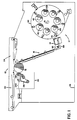
- the overall laser thermal printer proofer 10 of the present invention is illustrated generally schematically in Figure 1 and comprises a material supply assembly 12, a sheet cutter assembly 14, a sheet transport assembly 16, an imaging drum 18, a writehead assembly 20, a waste transport 22, and an image exit transport 24.
- the arrangement of the components within the enclosure or cabinet 26 is such that the imaging drum 18 and the writehead assembly 20 are disposed in the upper central region of the cabinet.
- the material supply assembly 12 is disposed in the lower portion at one end of the cabinet, with the sheet cutter assembly 14 disposed adjacent the material supply assembly, again in the lower portion of the cabinet.
- the sheet transport assembly 16 extends from the sheet cutter assembly 14 to adjacent the imaging drum 18, generally opposite to the writehead assembly 20.
- the overall operation of the apparatus comprises removing a portion of the supply of a receiver material from the material supply assembly 12, measuring it and cutting it to length in the sheet cutter assembly 14, and then transporting the cut sheet via sheet transport assembly 16 to the imaging drum 18 about which it is wrapped, registered, and secured.
- a length of donor material is then removed from the material supply assembly 12, cut to length by the sheet cutter assembly 14 and transported by the sheet transport assembly 16 to the imaging drum 18.
- the donor material is wrapped around the drum and superposed in the desired registration with the receiver material already secured thereon.
- the writehead assembly is traversed axially along the drum as the drum is rotated, and an image is imparted to the receiver sheet.
- the donor sheet is removed from the imaging drum, without disturbing the receiver sheet, and transported out of the apparatus via waste exit transport 22. Additional donor sheets are sequentially superposed with the receiver sheet on the drum and are imaged onto the receiver until the desired image is obtained and the completed image is exited from the apparatus via the image exit transport 24.
- the material supply assembly 12 comprises a carousel assembly 30 mounted for rotation about a horizontal axis 31 and has a plurality of material supporting spindles 42 each arranged to carry a roll supply of material 44 for use on the imaging drum 18.
- the carousel 30 is rotated about its axis to bring a selected roll supply of material into opposition with the sheet cutter assembly 14 where the material is removed from the roll supply, is fed through the cutter assembly 14, is measured, and is then cut.
- the sheet cutter assembly 14 is disposed adjacent the material supply carousel 30 at the material feed location and is arranged to receive the end of the web material as it is fed from the supply roll by the material feed assembly 46.
- the sheet cutter assembly employs a mating pair of cutter blades through which the web material is moved by the material feed assembly 46. After a sheet has been cut from the end of the roll of material, it is discharged from a metering drum 86 and belt 88, generally upwardly into a vertical sheet transport assembly 16.
- the sheet transport assembly delivers the cut sheet into close proximity with the imaging drum 18 where it is attached to the outer surface thereof.
- the imaging drum is mounted for rotation about its axis in a frame member, not shown.
- a thermal print medium for use with the printer proofer 10 of the present invention can be, for example, the medium disclosed in U.S. Patent No. 4,772,582, which includes a donor sheet having a material which strongly absorbs at the wavelength of the exposing light source. When the donor element is irradiated, this absorbing material converts light energy to thermal energy and transfers the heat to the dye in the immediate vicinity, thereby heating the dye to its vaporization temperature for transfer to the receiver element.
- the absorbing material may be present in a layer beneath the dye, or it may be admixed with the dye and is strongly absorptive to light having wavelengths in the range of 800nm - 880nm.
- An imaging light source is movable with respect to the imaging drum and is arranged to direct a beam of actinic light to the donor element.
- the light source comprises a plurality of laser diodes which can be individually modulated by electronic signals which are representative of the shape and color of the original image, so that each dye is heated to cause volatilization only in those areas in which its presence is required on the receiver to reconstruct the color of the original object.
- the laser diodes 206 are mounted remotely from the drum member 18, in a laser diode assembly 205 on a stationary portion of the frame member, and each direct the light produced thereby to the input end of a respective optical fiber 208 which extends to and transfers the light to the movable writing head assembly 20 adjacent the drum member.
- the laser diodes are selected to produce a first beam of light having wavelengths in the range of 800nm - 880nm, and preferably predominately at a wavelength of 830nm.
- the writehead assembly 20 is moveably supported adjacent the imaging drum 18 and comprises a writing head 218 which is mounted on a moving translator member 210.
- the writing head contains a linear array of optical fibers which includes a fiber-supporting wafer or substrate having a plurality of optical fibers mounted thereon, and have a writing end facing the drum member 18.
- the optical fibers extend as a bundle of fibers 242 from the opposite end of the printhead assembly to the diode laser assembly 205.
- the individual fibers 208 are each connected to the respective, remotely mounted diode lasers 206 which can be individually modulated to selectively project light from the writing end of the optical fibers through a lens assembly, onto the thermal print medium carried by the imaging drum 18.
- the fiber optic array may be of the type shown.
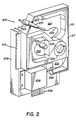
- the diode lasers 206 are individually disposed in a diode and fiber mount 207 which is illustrated in FIG. 2 and includes a heat sink 209 onto which the diode laser 206 is attached.
- the mount also includes a pair of oppositely disposed support and alignment ribs 210 and 212 disposed on opposite sides of the heat sink. The ribs are parallel with each other and may be in a common plane.
- An optical fiber guide and mode mixer 217 is also mounted in an enclosure 211 on the heat sink 209 and is provided with a cover plate 219 (See FIG. 3) which is attached to the enclosure as by a connector into a mounting post 220.
- the optical fiber guide and mode mixer 217 is formed of an open cell foam plastic and is provided with a cylindrical chamber 223, an outlet chamber 225, and a connector chamber 227.
- An optical fiber 229 is connected to the laser diode 206 and enters the fiber guide 217 through an entry chamber 232 in the enclosure 211.
- the fiber is wound in circular chamber 223 until substantially all the excess length thereof is accomodated and then the fiber is routed through outlet- or exit-chamber 225 into the connector chamber 227 where the fiber is attached to a connector 231.
- the connector 231 extends through an opening in the wall of the enclosure 211 where it is releasably held by a retainer 233.
- the circular chamber 223 is provided with a rigid cap or fiber retainer 235 which partially encloses the circumference of that chamber to prevent the fiber wouund therein from clockspringing out of the chamber during assembly.
- the cap is provided with a central opening and radial slots to the wall of the chamber to permit the fiber to be wound into the chamber through the open top thereof before the cover plate 219 is attached to the enclosure 211.
- the cap may be integrally formed with the enclosure or may be an insert applied during assembly. With this construction, a substantial length of fiber may be wound into the cylindrical chamber 223, providing mode mixing for the light passing therethrough and accomodating variations in the length of the fiber between the laser diode and the outlet connector 215.
- any odd length of fiber not accomodated by a full wrap within the cylindrical chamber 223 may be accomodated by the outlet chamber 225.
- the entrance chamber 232 accepts the strain relief 236, which encases the fiber as it leaves the diode case 206, and ensures that the fiber is enclosed to prevent the leakage of stray light therefrom before it enters the cylindrical chamber 223.
- the connector chamber 227 provides space for the storage of the connector 231 and its associated strain relief tubing 237 until it is connected to the laser diode assembly, as will be further described hereinbelow, and for a length of fiber that will permit the withdrawal of the connector from the retainer 233 for attachment to a mating connector on an adjacent portion of the assembly.
- the present invention provides a compact laser diode and optical fiber mount and guide assembly wherein the fiber is guided and held relatively stationary while providing the mode mixing and cladding mode stripping necessary to even out the light transmitted thereby, and at the same time accomodating a variable length of fiber with no modifications to the fiber necessary, while providing a releasable accomodation for the fiber connector during storage and handling until it is connected to the laser diode assembly.
- the laser diode 206 is provided with an edge connector 239 which is rigidly connected to the diode case and extends outwardly therefrom.
- edge connector 239 which is rigidly connected to the diode case and extends outwardly therefrom.
- Such laser diodes have been provided with electrical connections in the form of pins which require precise alignment and individual attachment to mating connectors to supply the necessary electrical connections to the laser diode assembly.
- Such prior art connectors for laser diode assemblies require costly and time consuming assembly in the apparatus with which they are associated.
- the present edge connector is so disposed as to extend outwardly from the diode casing adjacent an edge of the diode and fiber mount 207, but prferrably terminates inside the periphery of the mount to avoid unnecessary exposure to contact and possible damage during handling.
- the edge connector may be of the type normally used with printed circuit boards and is diposed in a plane parallel with or coplanar with the plane containing the support and alignment ribs 210 and 212.
- the laser diode assembly is provided with complimentary guide channels 250 mounted so as to accept the support and alignment ribs as the diode and fiber mount 207 is slid into position.
- a female socket 252 is also mounted in the same relationship with the guide channels 250 that the edge connector 239 has with the guide ribs 210 and 212 so that, as the mount 207 is slid along the guide channels, the edge connector 239 automatically lines up with and is inserted into the socket, completing the connection of the laser diode to its associated power and control circuitry.
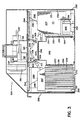
- the laser diode assembly 205 comprises an enclosure formed, for example of sheet metal, having end and side walls 280 and 282, respectively.
- the lower portion of the enclosure is divided into three chambers extending along the length of the enclosure created by vertical interior walls 284 which are connected at the top by a horizontal closure member 286.
- the central chamber 288 is substantially empty while the two lateral chambers 290 are arranged to accept a plurality of laser diode mounts 207 with the associated laser diodes 206.
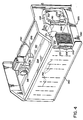
- a plurality of vertical guide channels 250 are mounted on the opposite side walls of each of the chambers 290 to accept the respective diode mounts 207 in substantially vertical spaced relationship.
- the general spacing and location of the laser diode and fiber mounts is indicated by the vertical phantom lines 292 (FIG. 4) which indicate that a total of eleven laser diodes may be accommodated by the front chamber 290.
- the rear chamber may accommodate the same or a different number of laser diodes.
- the top of the chambers are closed by removable closure plates 294 which are provided with spring fingers 296 associated with each of the laser diode assemblies 207 to resiliently urge the diode mounts into position when the cover plates 294 are secured in position.
- Each of the pairs of the guide channels 250 have associated therewith a female socket 252 located as described above with respect to the individual laser mounts. Means may be provided for directing cooling air through the chambers 290 to remove heat from the individual laser diodes.
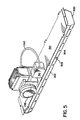
- a channel-shaped member 300 is disposed lengthwise between the two chambers 290 and above central chamber 288.
- the channel member 300 is provided with sidewalls having lower portions 302 which are angled with respect to the vertical and which are disposed substantially parallel with the facing portion of the laser diode and optical fiber mounts 207 disposed in chambers 290. Openings 304 (FIG. 5) are provided through the angled portions of the sidewall 302 which are generally in alignment with the connectors 231 of the laser diode mounts 207.
- Each of the openings are provided with a mating connector 306 for connection with the respective connectors 231 at the end of the fibers in each of the diode mounts.
- One of the connectors 231 is illustrated connected to connector 306 in the left-hand portion of Figure 3.
- the inner ends of connectors 306 mate with connectors 308 at the ends of the fibers 208 which extend to the write head 218 through the fiber bundle 242.
- the top of the channel-shaped member 300 is closed by closure plate 310 which carries on the upper surface thereof a mode mixing chamber 312 and transport brackets 314 for the write head 218.
- the optical fibers 208 extend from their respective connectors 308 through the interior of channel member 300 into the mode mixing chamber 312 where they are coiled to provide the desired mode mixing of the light being transported thereby and are then gathered into the bundle 242 which extends from the mode mixer 312 to the end of the write head 218 which, as illustrated is mounted during shipment on the supports 314 on the top of the channel member assembly.
- the writing head and fiber sub-assembly (FIG. 5), including the channel member 300, is separated from the remainder of the laser diode assembly and cover plates 294 are removed from the chambers 290 to permit insertion of the respective laser diode mounts 207.
- a mount is inserted by aligning the guide fins 210 and 212 with the respective channel members 250 and then sliding the mount downward until the edge connector 239 mates with the respective female socket 252.
- the writing head and fiber sub-assembly has been assembled by temporarily mounting the write head 218 in the temporary mounts 314 on the cover plate 310 of the channel-shaped member 300.
- the fiber bundle 242 extending from the end of the write head is connected at its opposite end to the mode mixer 312, also mounted on the cover plate 310.
- the optical fibers 208 from the bundle are wound a sufficient number of turns in the mode mixer to provide the mode mixing necessary and to accomodate any excess length thereof and are directed to the interior of the channel-shaped member 300 where the individual fibers, with their respective connectors 308, are connected to the inner ends of the mating connectors 306 which have been mounted through the respective holes 304 through the side walls 302 of the chamber.
- the cover plate is then attached to the channel-shaped member 300 and the assembled channel assembly is attached over the central chamber 288 of the laser diode assembly enclosure 205.
- the respective connectors 306 are disposed substantially in alignment with the respective connectors 231 of each laser diode mount. These connectors 231 are then pulled from the mount and connected to the connectors 306.
- the cover plates 294 are closed, completely enclosing all light generating and transmitting portions of the apparatus in a light-tight closure. Thereafter the write head 218 is removed from the temporary mounts 314 and is attached to the translator member 210.
- the present arrangement provides a laser diode assembly which is modular in form permitting the assembly and disassembly of various components individually and yet providing the necessary location stability for the optical fibers. Moreover, the laser diodes are completely enclosed as are all of the associated optical fibers, thereby reducing the possibility of radiation escaping therefrom.
Landscapes
- Physics & Mathematics (AREA)
- General Physics & Mathematics (AREA)
- Optics & Photonics (AREA)
- Engineering & Computer Science (AREA)
- Multimedia (AREA)
- Signal Processing (AREA)
- Electronic Switches (AREA)
- Light Guides In General And Applications Therefor (AREA)
- Semiconductor Lasers (AREA)
Claims (9)
- Optische Faser- und Diodenlaser-Halterung (207), die in einer ebenen Anordnung Befestigungsmittel (209) aufweist zur Anbringung eines Diodenlasers (206) auf einer Oberfläche davon, eine optische Faserführung (217) mit einem Einlaß (bei 236) und einem Auslaß (bei 237), und zwar angebracht benachbart zu dem Diodenlaser auf der erwähnten Oberfläche, wobei die Faserführung aufeinander folgende Mittel aufweist zur Bildung einer Einlaßkammer (232) benachbart zu dem Diodenlaser (206), eine im wesentlichen zylindrische Kammer (223), eine Auslaßkammer (225) und eine Verbinderkammer (227), wobei die Einlaßkammer (232) sich in die erwähnte im wesentlichen zylindrische Kammer (223) erstreckt, die durch die Auslaßkammer und die Verbinderkammer mit dem Auslaß in Verbindung steht und eine Achse aufweist, die sich senkrecht zu der erwähnten Oberfläche erstreckt und die Variationen der Länge der Faser zwischen dem Diodenlaser und einem Auslaßverbinder (231) am Auslaß unterbringt, und mit einer Abdeckplatte (219) angeordnet über der Faserführung entgegengesetzt zu den Befestigungsmitteln, wobei die optische Faser mit dem Diodenlaser verbunden ist und in die erwähnte Führung durch die Einlaßkammer eingeführt ist, um in der zylindrischen Kammer herumgewickelt zu sein und aus der Führung durch die Auslaßkammer und die Verbinderkammer auszutreten.
- Optische Faser- und Diodenlaser-Halterung (207) nach Anspruch 1, mit Haltemitteln (235) angeordnet in der zylindrischen Kammer (223), die die Faser darinnen aufgewickelt enthält, und zwar entgegen einem Austreten der Faser daraus während des Zusammenbaus.
- Optische Faser- und Diodenlaser-Halterung (207) nach Anspruch 1, wobei Haltemittel (233) vorgesehen sind um den Auslaßverbinder (231) in dem Auslaß freigebbar zu halten.
- Optische Faser- und Diodenlaser-Halterung (207) nach Anspruch 1, wobei die Auslaßkammer (225) einen bogenförmigen Innendurchlaß aufweist, der eine variable Faserlänge darinnen unterbringt.
- Optische Faser- und Diodenlaser-Halterung (207) nach Anspruch 1, wobei die Verbinderkammer (227) einen zweiten bogenförmigen Innendurchlaß aufweist, der eine variable Länge der Faser aufnimmt, die in der Verbinderkammer (227) enthalten ist, und daraus über einen endlichen Abstand hinweg heraus gezogen werden kann.
- Optische Faser- und Diodenlaser-Halterung (207) nach Anspruch 1, wobei die Befestigungsmittel (209) eine Wärmeaufnahme auf einer Seite entgegengesetzt zu der erwähnten Oberfläche aufweisen.
- Optische Faser- und Diodenlaser-Halterung (207) nach Anspruch 6, wobei die Führungsmittel (210, 212) integral auf den Befestigungs- oder Anordnungsmitteln (209) ausgeformt sind zur Verschiebung der optischen Faser- und Diodenlaser-Halterung in eine Umhüllung oder Umschließung (280, 282, 284, 286).
- Optische Faser- und Diodenlaser-Halterung (207) nach Anspruch 1, wobei die optische Faserführung aus einem offene Zellen aufweisenden Schaummaterial hergestellt ist.
- Verwendung einer optischen Faser- und Diodenlaser-Halterung (207) nach einem der vorhergehenden Ansprüche, in einer Vorrichtung zum automatischen Herstellen von Probenbildern mit voller Farbe unter Verwendung von Laserdioden zur Erzeugung thermischer Energie für eine Reihe von Farbdonoren oder Farbgebern zum selektiven Transfer jedes Farbstoffs in Ausrichtung mit einem Empfänger zur Bildung eines Probebildes.
Applications Claiming Priority (2)
| Application Number | Priority Date | Filing Date | Title |
|---|---|---|---|
| US07/762,831 US5214444A (en) | 1991-09-19 | 1991-09-19 | Optical fiber mount and support |
| US762831 | 1991-09-19 |
Publications (2)
| Publication Number | Publication Date |
|---|---|
| EP0533112A1 EP0533112A1 (de) | 1993-03-24 |
| EP0533112B1 true EP0533112B1 (de) | 1997-05-28 |
Family
ID=25066130
Family Applications (1)
| Application Number | Title | Priority Date | Filing Date |
|---|---|---|---|
| EP92115773A Expired - Lifetime EP0533112B1 (de) | 1991-09-19 | 1992-09-15 | Verbesserte Lichtwellenleiter-Halterung und -Träger |
Country Status (5)
| Country | Link |
|---|---|
| US (1) | US5214444A (de) |
| EP (1) | EP0533112B1 (de) |
| JP (1) | JP3262854B2 (de) |
| DE (1) | DE69219972T2 (de) |
| DK (1) | DK0533112T3 (de) |
Families Citing this family (25)
| Publication number | Priority date | Publication date | Assignee | Title |
|---|---|---|---|---|
| US5376954A (en) * | 1991-08-23 | 1994-12-27 | Eastman Kodak Company | Vacuum imaging drum with an axial flat in the periphery thereof |
| US5323180A (en) * | 1991-08-23 | 1994-06-21 | Eastman Kodak Company | Registration indicia on a drum periphery |
| EP0533110B1 (de) * | 1991-09-19 | 1995-03-15 | Eastman Kodak Company | Laserdiode mit Kartenrandverbinder |
| US5383051A (en) * | 1992-10-30 | 1995-01-17 | Pirelli Cavi S.P.A. | Compact-size optical amplifier |
| US5461693A (en) * | 1994-07-14 | 1995-10-24 | At&T Ipm Corp. | Optical fiber distribution frame with fiber testing |
| US5559922A (en) * | 1995-02-28 | 1996-09-24 | Lucent Technologies Inc. | Wire guide and optical fiber storage spool assembly |
| US5943461A (en) * | 1997-05-12 | 1999-08-24 | Lucent Technologies Inc | Connectorized optical module package and method using same with internal fiber connections |
| US6799902B2 (en) | 2000-12-26 | 2004-10-05 | Emcore Corporation | Optoelectronic mounting structure |
| US20020122637A1 (en) * | 2000-12-26 | 2002-09-05 | Anderson Gene R. | Optical transmitter, receiver or transceiver module |
| US6905260B2 (en) | 2000-12-26 | 2005-06-14 | Emcore Corporation | Method and apparatus for coupling optical elements to optoelectronic devices for manufacturing optical transceiver modules |
| US7021836B2 (en) * | 2000-12-26 | 2006-04-04 | Emcore Corporation | Attenuator and conditioner |
| US6863444B2 (en) * | 2000-12-26 | 2005-03-08 | Emcore Corporation | Housing and mounting structure |
| US6867377B2 (en) * | 2000-12-26 | 2005-03-15 | Emcore Corporation | Apparatus and method of using flexible printed circuit board in optical transceiver device |
| US20020117571A1 (en) * | 2001-02-23 | 2002-08-29 | Dane Scott | Method and system for automatic handling of optical assemblies |
| US6714232B2 (en) * | 2001-08-30 | 2004-03-30 | Eastman Kodak Company | Image producing process and apparatus with magnetic load roller |
| US6476849B1 (en) | 2001-09-04 | 2002-11-05 | Eastman Kodak Company | Image processing apparatus with internal scanner |
| US6667758B2 (en) | 2001-09-04 | 2003-12-23 | Eastman Kodak Company | Image processing apparatus and method for simultaneously scanning and proofing |
| US6614463B2 (en) | 2001-10-05 | 2003-09-02 | Eastman Kodak Company | Image processing apparatus with conduit tube and blower |
| USD468707S1 (en) | 2001-10-31 | 2003-01-14 | Hon Hai Precision Ind. Co., Ltd. | Holder of optical switch equipment |
| US6677975B1 (en) | 2002-06-19 | 2004-01-13 | Eastman Kodak Company | System and process for magnetic alignment of an imaging subsystem |
| US6863453B2 (en) * | 2003-01-28 | 2005-03-08 | Emcore Corporation | Method and apparatus for parallel optical transceiver module assembly |
| GB2409289B (en) * | 2003-12-15 | 2007-06-06 | Weatherford Lamb | Feedthrough fibre strain relief |
| US7412147B2 (en) * | 2005-03-15 | 2008-08-12 | Adc Telecommunications, Inc. | Normal through optical panel |
| US9001862B2 (en) * | 2012-03-09 | 2015-04-07 | Raytheon Company | Miniaturized solid-state lasing device, system and method |
| JP6159239B2 (ja) * | 2013-12-09 | 2017-07-05 | APRESIA Systems株式会社 | 光通信モジュール及び光通信装置 |
Family Cites Families (9)
| Publication number | Priority date | Publication date | Assignee | Title |
|---|---|---|---|---|
| US4360729A (en) * | 1980-11-17 | 1982-11-23 | Geosource Inc. | Seismic cable connector with optical transceiver |
| FR2603118A1 (fr) * | 1986-08-20 | 1988-02-26 | Mach App Et Const | Phototraceur a rouleau multifaisceau |
| US4861134A (en) * | 1988-06-29 | 1989-08-29 | American Telephone And Telegraph Company, At&T Bell Laboratories | Opto-electronic and optical fiber interface arrangement |
| JPH07111510B2 (ja) * | 1988-08-22 | 1995-11-29 | 大日本スクリーン製造株式会社 | 画像走査記録装置 |
| JP2877407B2 (ja) * | 1990-01-08 | 1999-03-31 | 住友電気工業株式会社 | 光ファイバ余長収納ケース |
| GB9004244D0 (en) * | 1990-02-26 | 1990-04-18 | Plessey Telecomm | Optical fibre storage apparatus |
| US5146242A (en) * | 1991-03-15 | 1992-09-08 | Eastman Kodak Company | Writing beam angular alignment device |
| US5146241A (en) * | 1991-03-15 | 1992-09-08 | Eastman Kodak Company | Automatic cut-out for auto-focus device |
| US5097529A (en) * | 1991-03-22 | 1992-03-17 | At&T Bell Laboratories | Space-saving optical fiber cable closure |
-
1991
- 1991-09-19 US US07/762,831 patent/US5214444A/en not_active Expired - Lifetime
-
1992
- 1992-09-15 DE DE69219972T patent/DE69219972T2/de not_active Expired - Fee Related
- 1992-09-15 EP EP92115773A patent/EP0533112B1/de not_active Expired - Lifetime
- 1992-09-15 DK DK92115773.1T patent/DK0533112T3/da active
- 1992-09-18 JP JP24938192A patent/JP3262854B2/ja not_active Expired - Fee Related
Also Published As
| Publication number | Publication date |
|---|---|
| DK0533112T3 (da) | 1997-07-28 |
| DE69219972T2 (de) | 1998-01-15 |
| DE69219972D1 (de) | 1997-07-03 |
| JPH0688912A (ja) | 1994-03-29 |
| JP3262854B2 (ja) | 2002-03-04 |
| EP0533112A1 (de) | 1993-03-24 |
| US5214444A (en) | 1993-05-25 |
Similar Documents
| Publication | Publication Date | Title |
|---|---|---|
| EP0533112B1 (de) | Verbesserte Lichtwellenleiter-Halterung und -Träger | |
| US5268708A (en) | Laser thermal printer with an automatic material supply | |
| US20010035900A1 (en) | Thermal printer, thermal printing method and conveyor for recording material | |
| US5376954A (en) | Vacuum imaging drum with an axial flat in the periphery thereof | |
| US5276464A (en) | Method and apparatus for loading and unloading superposed sheets on a vacuum drum | |
| US5428371A (en) | Laser thermal printer using roll material supply | |
| US5196866A (en) | Focus fiber mount | |
| EP0535441B1 (de) | Anordnung mit Schreibkopf mit Vielfachlaserdiodenhalterung | |
| US5260714A (en) | Method of removing air from between superposed sheets | |
| US5323180A (en) | Registration indicia on a drum periphery | |
| US5270731A (en) | Laser thermal printer with positive air flow | |
| US5257038A (en) | Focusing laser diode mount on a write head | |
| EP0533110B1 (de) | Laserdiode mit Kartenrandverbinder | |
| US5301099A (en) | Vacuum imaging drum with a material receiving recess in the periphery thereof | |
| US5280307A (en) | Selectively wound material for a laser thermal printer | |
| US5323178A (en) | Material supply carousel | |
| US5146241A (en) | Automatic cut-out for auto-focus device | |
| EP0529563A2 (de) | Abbildungsgerät und Gewindespindelantrieb | |
| EP0530634B1 (de) | Bildaufzeichnungstrommel | |
| US5278579A (en) | Optical fiber support and storage device | |
| EP0529561B1 (de) | Laserdiodeträger mit Autofokusvorrichtung | |
| JP4056590B2 (ja) | 画像記録装置 | |
| US5270733A (en) | Material transport that selectively contacts different materials | |
| US5220344A (en) | Initial set-up procedure for an auto-focus lens | |
| US5260721A (en) | Precision lead screw drive assembly |
Legal Events
| Date | Code | Title | Description |
|---|---|---|---|
| PUAI | Public reference made under article 153(3) epc to a published international application that has entered the european phase |
Free format text: ORIGINAL CODE: 0009012 |
|
| AK | Designated contracting states |
Kind code of ref document: A1 Designated state(s): DE DK FR GB NL |
|
| 17P | Request for examination filed |
Effective date: 19930924 |
|
| 17Q | First examination report despatched |
Effective date: 19950914 |
|
| GRAG | Despatch of communication of intention to grant |
Free format text: ORIGINAL CODE: EPIDOS AGRA |
|
| GRAH | Despatch of communication of intention to grant a patent |
Free format text: ORIGINAL CODE: EPIDOS IGRA |
|
| GRAH | Despatch of communication of intention to grant a patent |
Free format text: ORIGINAL CODE: EPIDOS IGRA |
|
| GRAA | (expected) grant |
Free format text: ORIGINAL CODE: 0009210 |
|
| AK | Designated contracting states |
Kind code of ref document: B1 Designated state(s): DE DK FR GB NL |
|
| PGFP | Annual fee paid to national office [announced via postgrant information from national office to epo] |
Ref country code: NL Payment date: 19970625 Year of fee payment: 6 |
|
| REF | Corresponds to: |
Ref document number: 69219972 Country of ref document: DE Date of ref document: 19970703 |
|
| REG | Reference to a national code |
Ref country code: DK Ref legal event code: T3 |
|
| ET | Fr: translation filed | ||
| PLBE | No opposition filed within time limit |
Free format text: ORIGINAL CODE: 0009261 |
|
| 26N | No opposition filed | ||
| PG25 | Lapsed in a contracting state [announced via postgrant information from national office to epo] |
Ref country code: NL Free format text: LAPSE BECAUSE OF NON-PAYMENT OF DUE FEES Effective date: 19990401 |
|
| NLV4 | Nl: lapsed or anulled due to non-payment of the annual fee |
Effective date: 19990401 |
|
| PGFP | Annual fee paid to national office [announced via postgrant information from national office to epo] |
Ref country code: DK Payment date: 20000614 Year of fee payment: 9 |
|
| PGFP | Annual fee paid to national office [announced via postgrant information from national office to epo] |
Ref country code: FR Payment date: 20000905 Year of fee payment: 9 |
|
| PGFP | Annual fee paid to national office [announced via postgrant information from national office to epo] |
Ref country code: DE Payment date: 20000928 Year of fee payment: 9 |
|
| PGFP | Annual fee paid to national office [announced via postgrant information from national office to epo] |
Ref country code: GB Payment date: 20010807 Year of fee payment: 10 |
|
| PG25 | Lapsed in a contracting state [announced via postgrant information from national office to epo] |
Ref country code: DK Free format text: LAPSE BECAUSE OF NON-PAYMENT OF DUE FEES Effective date: 20010915 |
|
| REG | Reference to a national code |
Ref country code: GB Ref legal event code: IF02 |
|
| PG25 | Lapsed in a contracting state [announced via postgrant information from national office to epo] |
Ref country code: DE Free format text: LAPSE BECAUSE OF NON-PAYMENT OF DUE FEES Effective date: 20020501 |
|
| PG25 | Lapsed in a contracting state [announced via postgrant information from national office to epo] |
Ref country code: FR Free format text: LAPSE BECAUSE OF NON-PAYMENT OF DUE FEES Effective date: 20020531 |
|
| REG | Reference to a national code |
Ref country code: DK Ref legal event code: EBP |
|
| REG | Reference to a national code |
Ref country code: FR Ref legal event code: ST |
|
| PG25 | Lapsed in a contracting state [announced via postgrant information from national office to epo] |
Ref country code: GB Free format text: LAPSE BECAUSE OF NON-PAYMENT OF DUE FEES Effective date: 20020915 |
|
| GBPC | Gb: european patent ceased through non-payment of renewal fee |
Effective date: 20020915 |