EP0533376B1 - Supports ou dispositifs d'appui portatifs - Google Patents
Supports ou dispositifs d'appui portatifs Download PDFInfo
- Publication number
- EP0533376B1 EP0533376B1 EP92308005A EP92308005A EP0533376B1 EP 0533376 B1 EP0533376 B1 EP 0533376B1 EP 92308005 A EP92308005 A EP 92308005A EP 92308005 A EP92308005 A EP 92308005A EP 0533376 B1 EP0533376 B1 EP 0533376B1
- Authority
- EP
- European Patent Office
- Prior art keywords
- leg
- members
- extensible support
- clamping
- support leg
- Prior art date
- Legal status (The legal status is an assumption and is not a legal conclusion. Google has not performed a legal analysis and makes no representation as to the accuracy of the status listed.)
- Expired - Lifetime
Links
- 125000006850 spacer group Chemical group 0.000 claims description 26
- 239000000463 material Substances 0.000 claims description 5
- 230000000295 complement effect Effects 0.000 claims description 2
- 230000001419 dependent effect Effects 0.000 claims 1
- 238000006073 displacement reaction Methods 0.000 description 4
- 239000004677 Nylon Substances 0.000 description 3
- 229920001778 nylon Polymers 0.000 description 3
- 239000000428 dust Substances 0.000 description 2
- 239000004033 plastic Substances 0.000 description 2
- 229920003023 plastic Polymers 0.000 description 2
- 239000000853 adhesive Substances 0.000 description 1
- 230000001070 adhesive effect Effects 0.000 description 1
- 230000002411 adverse Effects 0.000 description 1
- 238000004140 cleaning Methods 0.000 description 1
- 229910001234 light alloy Inorganic materials 0.000 description 1
- 239000002184 metal Substances 0.000 description 1
- 239000002245 particle Substances 0.000 description 1
- 239000011236 particulate material Substances 0.000 description 1
- 239000004576 sand Substances 0.000 description 1
Images


Classifications
-
- F—MECHANICAL ENGINEERING; LIGHTING; HEATING; WEAPONS; BLASTING
- F16—ENGINEERING ELEMENTS AND UNITS; GENERAL MEASURES FOR PRODUCING AND MAINTAINING EFFECTIVE FUNCTIONING OF MACHINES OR INSTALLATIONS; THERMAL INSULATION IN GENERAL
- F16M—FRAMES, CASINGS OR BEDS OF ENGINES, MACHINES OR APPARATUS, NOT SPECIFIC TO ENGINES, MACHINES OR APPARATUS PROVIDED FOR ELSEWHERE; STANDS; SUPPORTS
- F16M11/00—Stands or trestles as supports for apparatus or articles placed thereon ; Stands for scientific apparatus such as gravitational force meters
- F16M11/20—Undercarriages with or without wheels
- F16M11/24—Undercarriages with or without wheels changeable in height or length of legs, also for transport only, e.g. by means of tubes screwed into each other
- F16M11/26—Undercarriages with or without wheels changeable in height or length of legs, also for transport only, e.g. by means of tubes screwed into each other by telescoping, with or without folding
- F16M11/32—Undercarriages for supports with three or more telescoping legs
- F16M11/36—Members preventing slipping of the feet
-
- F—MECHANICAL ENGINEERING; LIGHTING; HEATING; WEAPONS; BLASTING
- F16—ENGINEERING ELEMENTS AND UNITS; GENERAL MEASURES FOR PRODUCING AND MAINTAINING EFFECTIVE FUNCTIONING OF MACHINES OR INSTALLATIONS; THERMAL INSULATION IN GENERAL
- F16M—FRAMES, CASINGS OR BEDS OF ENGINES, MACHINES OR APPARATUS, NOT SPECIFIC TO ENGINES, MACHINES OR APPARATUS PROVIDED FOR ELSEWHERE; STANDS; SUPPORTS
- F16M2200/00—Details of stands or supports
- F16M2200/02—Locking means
- F16M2200/025—Locking means for translational movement
- F16M2200/028—Locking means for translational movement by positive interaction, e.g. male-female connections
Definitions
- This invention relates to portable stands or supports.
- it relates to stands or supports of the type on which a film camera, lighting or other apparatus can be mounted.
- Such stands are generally in the form of tripods, which provide the most stable support but may alternatively be monopods, bipods or have any other number of legs.
- Such a stand or support be adjustable in height.
- Previously available stands have only had a limited amount of adjustability. Therefore, in situations where it is considered that a large amount of height adjustment may be necessary, such as during electronic news gathering (ENG) operations, an operator will often take two different stand apparatuses, a first one having a first height adjustment and a second one having a second height adjustment. This increases the amount of equipment necessary and is clearly undesirable when speed and manoeuvrability are required by the camera or other equipment and its operator to follow a particular series of events.
- ENG electronic news gathering
- DE-U-8 812 402 discloses an extensible support leg for a portable stand or support comprising a plurality of pairs of parallel elongate leg members arranged in two or more planes, the leg members being extensible by sliding movement between pairs in respective first and second planes, and means for releasably locking the leg members in any desired positions.
- an extensible support leg for a portable stand or support comprising a plurality of pairs of parallel elongate leg members, the pairs being arranged in two or more planes, the leg members being extensible by sliding movement between pairs in respective first and second planes, and means for releasably locking the leg members in any desired position, characterised in that each leg member in the second plane lies behind a respective leg member in the first plane, such that the plane common to the axes of said leg members is perpendicular to the first and second planes.
- each pair of leg members is spaced apart at their ends by rigid spacers, forming a box-sectioned portion, at least one of said spacers having through holes for slidably receiving a second pair of leg members.
- the locking means may comprise a body portion having at least two spaced retaining holes passing therethrough, each retaining hole slidably receiving a leg member, the leg members being substantially parallel and providing the second leg part; the body portion defining a housing which is located between the retaining holes and receives a locking member, the locking member having two planar abutment surfaces forming angles of less than 90° with the longitudinal axis thereof and being located in the housing and capable of longitudinal adjustment within the housing; the housing communicating with each retaining hole through one of a plurality of internal passages provided in the body portion within each of which passages is slidably located a clamping member having a planar surface having a complementary angle to an abutment surface for engaging the respective abutment surface, each clamping member having a length greater than the length of the internal passage in which it is located; wherein the second leg part can be clamped relative to the first leg part by longitudinal adjustment of the locking member relative to the body portion to cause the abutment surfaces of the locking member to engage and slide over the
- the locking member is preferably floatingly located in the housing, and may be of trapezoidal shape having at least two abutment surfaces forming the tapered sides thereof.
- the clamping members preferably act upon shoes which clamp the extension members.
- the clamping members may be supported for relative rotation about their longitudinal axis, and therefore with respect to the shoes and the trapezoidal block, so that longitudinal adjustment of the block causes rotational adjustment of the clamping members to abuttingly align the planar surfaces.
- the clamping surfaces may be supported by the shoes by a spigot and recess, there being a tolerance between the spigot and recess diameters, to allow relative rotation of the spigot and recess, and therefore relative rotation of the shoe and clamping member.
- the clamping member may be otherwise floating within the housing.
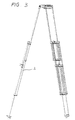
- a two-stage tripod comprises a mounting or head 1 for receiving a camera or other apparatus hingeably mounted to three leg portions 2.
- the leg portions 2 each comprise a plurality of tubular leg members or struts 3. These are spaced apart and interconnected such that they all lie parallel and spaced apart and so that at least some of the leg parts 3 can slide axially with respect to the other parts to the lengthen or shorten a leg to raise or lower the support member 1 from the ground.
- Each leg part 2 contacts a ground surface by means of one or more spikes 48 shown more clearly in Figures 6 and 7. It is well-known that a tripod structure is the most stable but the invention is equally applicable to other structures such as monopods or four-legged ones for example.
- the tripod shown is a two-stage tripod, that is there are two stages involved in the height adjusting mechanism for each leg. As shown in Figures 2 and 3, this mechanism involves the relative sliding in an axial direction of respective pairs of strut members 3.
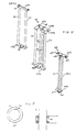
- Each leg comprises three parts which are adapted to slide with respect to one another. These parts are shown in Figure 4 as 20, 30 and 40.
- Each part comprises at least one pair of parallel tubular struts or leg members which may be made of a light alloy, or a strong plastics material for example.
- the struts are spaced apart at their ends by spacer bars which serve to make a strong box-sectioned structure for maximum stability and strength.
- the bars may be screwed in place or otherwise fitted, perhaps by the use of adhesive.
- Top bar 24a mounts a rotatable rod 23 which can be used to mount the leg to a head and to other legs of a tripod in conventional manner.
- Bar 24b includes two through holes 25 which are mounted in colinear manner with the bars 21 and 22.
- the tubular members 21 and 22 are typically of approximately 1.2 cm diameter. They are made of a material which is strong and is substantially resistant to significant flexing in the transverse direction.
- Part 30 comprises two parallel pairs of legs 31, 32 and 36, 37.
- the legs are secured and spaced apart by respective top and bottom spacers 34a and 34b.
- tubular members 31 and 32 lie towards the front of the part and are spaced approximately 8.5 cm apart, ie the same spacing as the legs 21, 22 of part 20.
- Parts 36 and 37 lie in a plane approximately 2 cm behind the first plane and are spaced apart by approximately 4 cm.
- Spacer bar 34a is generally U-shaped in plan view and bars 31 and 32 are secured to the underside of the leg parts of the U whilst 36 and 37 are secured to the back part thereof. Through holes 35a are formed towards the rear edges of the U as shown.
- Spacer 34a includes a locking mechanism as will be described further below so that it can lock tubular members sliding with respect to apertures 35a into any desired position.
- the locking mechanism includes a locking lever 38.
- Bottom spacer 34b is of T-shape in plan view, with the cross-piece of the T being towards the front and supporting the two front members 31 and 32 towards its edges and the stem being towards the rear and supporting bars 36 and 37.
- Through holes 35b are formed in the T-shaped spacer positions generally colinear with bars 31 and 32.
- Part 40 comprises a single pair of tubular parallel members spaced approximately 4 cm apart (ie the same spacing as tubes 36,37).
- the top spacer of this part 44a is of approximately the same length as the top spacers 24a and 34a and is a locking bar, having a locking mechanism similar to that of part 34a and having a locking lever 48.
- Spacer 44a is provided with two through holes 45 in which a relatively sliding tubular bar can be locked in any desired position.
- Bottom spacer 44b includes a front eye portion 47 and two spikes 48 adapted to rest against the ground when the leg is in operation.
- tubular leg parts are preferably assembled in place and the respective spacer bars secured thereto progressively by screwing through screw holes on the side of the spacer bars.
- the structure is as follows.
- Tubes 21 and 22 extend through through-holes 35a in part 30.
- tubes 36 and 37 of part 30 lie colinear with tubes 21 and 22 and tubes 31 and 32 lie in front of the plane formed by legs 21, 22, 36 and 37.
- Tubes 21 and 22 are slidably displaceable with respect to through holes 35a and can be locked at any desired position by the locking mechanism described below.
- Tubes 31 and 32 are in turn mounted within, and therefore slidably displaceable with respect to, through holes 45 in part 40.
- the relative position of parts 30 and 40 can be varied and locked at will.
- the height of the leg can be adjusted in a two stage mechanism involving firstly displacement of part 30 with respect to part 20 and secondly displacement of part 40 with respect to part 30.
- each tubular part of the structure is secured at either end to a spacer which is fixed with respect to that tube but is also slidably displaceable through a spacer belonging to another part. Accordingly, at any time a series of box sections in two planes are formed, leading to a strong structure.
- low friction rings 60 are mounted in radial grooves 61 in a spacer bar.
- the rings are typically made of nylon or another suitable plastics or other material and are split as shown at 62. This split starts at the inner face of the ring and is generally tangential thereto and extends to the outside thereof. Such a split tends to make the ring try to close and therefore the ring tightly grips a tube sliding within it. Hence, during relative movement of the tube and the ring the tube is wiped by the ring, thus providing a cleaning action.
- the ring also prevents the ingress of particulate material such as sand or ice, enabling the leg and support stand to be used in environments which were previously considered too hostile, such as deserts or arctic regions.
- the radial grooves 61 may, in some embodiments, be of greater depth than the diameter of a ring 60.
- the locking mechanism described below tends to push a tube laterally outwards from the longitudinal axis of the leg.
- the nylon ring is pushed into the groove and the side of the tube abuts directly against the metal or other material surface of the spacer, providing a firmer joint.
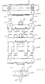
- Figure 6 shows a schematic front view of an assembled leg. This figure shows in more detail how the parts are assembled together and shows how from top to bottom the spacers would be assembled in the order 24a, 34a, 44a, 24b, 34b and 44b. This relative disposition will always be maintained no matter what the degree of extension. It should be noted that the tubes lie in two planes, one underneath the other in the figure. For instance, tubes 36 and 37 extend behind tubes 41 and 42, similarly tubes 21 and 22 extend behind tubes 31 and 32.
- Figure 7 illustrates a side view of Figure 6, showing more clearly the two planes and how the various box sections are constructed.
- Figure 8 shows a cross section through the lockable space bar 44a, illustrating the locking mechanism.
- the locking lever 48 is mounted on the end of a shaft 49.
- the shaft is adapted to act upon a trapezoidal block 50, to raise or lower the block with respect to the housing.
- the block 50 is square or rectangular in plan view and is disposed in an opening in the bar 44a with a clearance between the opening and the block such that the block is to some extent floating in the opening and can, together with shaft 49, tilt about the horizontal axis into the paper in the figure.
- Block 50 has tapered planar side edges 51 which are adapted to abut against respective clamping members 52, which have wedge shaped portions 54 at one end, having correspondingly tapered, planar, edges to block 50.
- Wedge portions 54 are connected via rods 55 to end pieces 56, having an end spigot 57.
- Members 52 are arranged for longitudinal displacement through respective internal passages 53, which communicate with the through holes 45, for receiving tubular members 31 and 32.
- Spigot 57 locates inside a corresponding shaped recess in a shoe 58, which may be of nylon in one embodiment.
- Shoe 58 acts upon a tube 31 or 32 in through hole 45 to lock the tube with respect to spacer 44a.
- the tube contacting surface of the shoe may have a correspondingly arcuate surface to the tube wall, ensuring a surface, rather than point, contact.
- Locking lever 48 acts in one embodiment to rotate shaft 49 by approximately a quarter turn between its fully unlocked and fully locked position.
- Lever 48 is spaced from the spacer bar 44a by one or more washers 59, and in the locked position (shown in Figures 6, 7 and 8) extends perpendicularly to the longitudinal axis of the leg.
- Shaft 49 acts to raise block 50 when rotated. This may be done by cooperating screwthreads or by a cam action.
- the shaft may have an elliptic or other eccentric cross-section over part or all of its length, which cooperates with an internal profile of the block, to raise or lower the block, and hence to cause the floating block to move into abutment with wedge portions 54 and subsequently to cause longitudinal outward displacement of members 52 to lock tubes 31 and 32.
- the shaft 49 may have one or more flats or planar portions on its periphery, acting in cooperating with the internal surface of block 50.
- block 50 enables variations in the spacing of the tubular member, for example, to be compensated for, since the block will automatically centre the mechanism when drawn into a locking position. It can also compensate for unevenness on a tube surface, caused by dust for example. Since a planar contact occurs between faces of block 50 and wedges 54, the pressure is distributed over the contacting faces and the mechanism tends to wear far slower than in conventional locking systems which use point contact between curved or conical bodies.
- the clamping members 52 are also floating, so that the spigots 57 only loosely fit into recesses in shoes 58, allowing for rotation of the clamping member about its longitudinal axis.
- wedge piece 54 can rotate with respect to trapezoidal block 50. In use, when block 50 is drawn upwards, wedge 54 will automatically be rotated into abutting planar alignment with block 50 to clamp a tubular member 31 or 32. This avoids the need for accurate angular alignment of the clamping member and shoe, as was required in a previously proposed locking mechanism which usually involved placing the mechanism in a complex jig for alignment.
- the clamping members 52 automatically self-align with respect to the block 50 upon actuation of block 50, since they are rotably supported with respect to shoe 58, and block 50.
- the self-alignment ensures that both clamping members are aligned, and both are displaced to tightly grip a respective tubular member. In systems where pre-alignment is necessary, it is sometimes found that one tube is tightly gripped, but the other is gripped more loosely, allowing for slippage and loss of rigidity.
- the locking lever need not be mounted on the top surface of the mechanism.
- the lever By rotating the mechanism about the axis of the clamping member 52, the lever could alternatively be mounted on the front, bottom or rear of the mechanism. In one example, the lever is mounted on the front. This can reduce the possibility of the lever inadvertently being turned from a locked to an unlocked position, for example.
- the protruding locking lever may be replaced by other actuators, such as rotating knobs, or sliding devices for example performing the same function of causing relative motion of the trapezoidal block 50 and wedges 54.
Landscapes
- Engineering & Computer Science (AREA)
- General Engineering & Computer Science (AREA)
- Mechanical Engineering (AREA)
- Accessories Of Cameras (AREA)
Claims (15)
- Pied de support extensible pour un dispositif d'appui ou support portable comportant plusieurs paires d'éléments de pied allongés parallèles (21, 22 ; 31, 32 ; 36, 37 ; 41, 42), ces paires étant disposées dans au moins deux plans, lesdits éléments de pied étant extensibles par un mouvement de coulissement entre les paires dans un premier plan et un deuxième plan respectifs, et des moyens pour verrouiller de façon libérable les éléments de pied à une position désirée quelconque, caractérisé en ce que chaque élément de pied (31, 32 ; 41, 42) du deuxième plan s'étend derrière un élément de pied respectif (21, 22; 36, 37) du premier plan, de sorte que chaque plan commun aux axes de chaque élément de pied respectif est perpendiculaire aux premier et deuxième plans.
- Pied de support extensible selon la revendication 1, dans lequel les éléments de pied de chaque paire sont espacés l'un de l'autre à leurs extrémités au moyen d'entretoises rigides (24, 34, 44) formant une portion à section en caisson, l'une au moins de ces entretoises présentant des trous traversants (25, 35, 45) pour recevoir à coulissement une deuxième paire d'éléments de pied.
- Pied de support extensible selon la revendication 1 ou la revendication 2, comprenant une première partie de pied (20) formée d'une paire d'éléments de pied parallèles (21, 22) dans un premier plan ; une deuxième partie de pied (30) formée par une paire d'éléments de pied parallèles (36, 37) dans ledit premier plan et par une paire d'éléments de pied parallèles (31, 32) dans un deuxième plan ; et une troisième partie de pied (40) formée par une paire d'éléments de pied parallèles (41, 42) dans ledit deuxième plan, dans lequel le pied de support extensible est assemblé en reliant ensemble la première partie de pied à la deuxième partie de pied et la deuxième partie de pied à la troisième partie de pied.
- Pied de support extensible selon la revendication 2, ou la revendication 3 lorsqu'elle dépend de la revendication 2, dans lequel les moyens de verrouillage sont associés à certaines des entretoises.
- Pied de support extensible selon l'une quelconque des revendications 2 à 4, dans lequel les entretoises présentant des trous traversants présentent une gorge radiale interne (61) et un anneau fendu (60) à bas coefficient de frottement monté à l'intérieur de la gorge, la gorge présentant un diamètre supérieur au diamètre de l'anneau, de sorte qu'un intervalle de tolérance existe entre eux, l'anneau étant fendu de telle façon qu'il ait tendance à se serrer autour d'une partie de pied insérée pour empêcher l'intrusion d'un corps étranger.
- Pied de support extensible selon la revendication 5, dans lequel la fente (62) s'étend à partir de la face interne de l'anneau et est essentiellement tangente à celui-ci.
- Pied de support extensible selon l'une quelconque des revendications précédentes, dans lequel les moyens de verrouillage comprennent une portion de corps présentant au moins deux trous de retenue espacés (45) passant à travers celle-ci, chaque trou de retenue recevant à coulissement un élément de pied (31, 32), les éléments de pied étant sensiblement parallèles et formant la deuxième partie de pied ; la portion de corps définissant un logement qui est situé entre les trous de retenue et reçoit un élément de verrouillage (50), ledit élément de verrouillage ayant deux surfaces de butée planes (51) formant des angles inférieurs à 90° avec l'axe longitudinal de celui-ci, et étant situé dans le logement en pouvant être réglé suivant la direction longitudinale à l'intérieur dudit logement ; le logement communiquant avec chaque trou de retenue à travers l'un de plusieurs passages internes (53) ménagés dans la portion de corps, un élément de blocage (52) étant monté à coulissement dans chacun de ces passages, cet élément présentant une surface plane formant un angle complémentaire avec une surface de butée pour venir en engagement avec la surface de butée respective, chaque élément de blocage ayant une longueur supérieure à la longueur du passage interne dans lequel il est situé ; dans lequel la deuxième partie de pied peut être bloquée par rapport à la première partie de pied par réglage longitudinal de l'élément de verrouillage par rapport à la portion de corps, pour provoquer l'engagement des surfaces de butée de l'élément de verrouillage avec les surfaces de butée respectives des éléments de blocage, et leur coulissement sur celles-ci, afin de solliciter lesdits éléments en direction de leurs trous de retenue respectifs et ainsi bloquer les éléments de pied dans leurs trous de retenue respectifs.
- Pied de support extensible selon la revendication 7, dans lequel l'élément de verrouillage est monté flottant dans le logement.
- Pied de support extensible selon la revendication 7 ou la revendication 8, dans lequel l'élément de verrouillage a une forme trapézoïdale et présente au moins deux surfaces de butée constituant les côtés inclinés de celui-ci.
- Pied de support extensible selon l'une quelconque des revendications 7 à 9, dans lequel les moyens de blocage comprennent des sabots (58) sur lesquels les éléments de blocage agissent pour bloquer les éléments d'extension.
- Pied de support extensible selon l'une quelconque des revendications 7 à 10, dans lequel l'élément de blocage est monté flottant dans le logement.
- Pied de support extensible selon la revendication 11, dans lequel les éléments de blocage sont montés afin d'être mobiles en rotation relative par rapport aux sabots et aux éléments de verrouillage, de telle sorte que le réglage longitudinal des éléments de verrouillage provoque le réglage en rotation des éléments de blocage pour aligner en butée les surfaces planes de l'élément de verrouillage et des éléments de blocage.
- Pied de support extensible selon la revendication 12, dans lequel chaque élément de blocage comporte un goujon (51) ayant une forme adaptée pour l'insérer dans une cavité de forme correspondante de chaque sabot, un intervalle de tolérance existant entre les diamètres du goujon et de la cavité pour permettre la rotation relative des éléments de blocage par rapport aux sabots.
- Dispositif d'appui ou support portable comportant au moins un pied de support extensible selon l'une quelconque des revendications précédentes.
- Dispositif d'appui ou support portable selon la revendication 14, qui est un trépied comportant trois pieds de support extensibles.
Applications Claiming Priority (2)
| Application Number | Priority Date | Filing Date | Title |
|---|---|---|---|
| GB919119679A GB9119679D0 (en) | 1991-09-14 | 1991-09-14 | Portable stands or supports |
| GB9119679 | 1991-09-14 |
Publications (2)
| Publication Number | Publication Date |
|---|---|
| EP0533376A1 EP0533376A1 (fr) | 1993-03-24 |
| EP0533376B1 true EP0533376B1 (fr) | 1996-01-03 |
Family
ID=10701424
Family Applications (1)
| Application Number | Title | Priority Date | Filing Date |
|---|---|---|---|
| EP92308005A Expired - Lifetime EP0533376B1 (fr) | 1991-09-14 | 1992-09-03 | Supports ou dispositifs d'appui portatifs |
Country Status (4)
| Country | Link |
|---|---|
| US (1) | US5320316A (fr) |
| EP (1) | EP0533376B1 (fr) |
| DE (1) | DE69207315T2 (fr) |
| GB (1) | GB9119679D0 (fr) |
Families Citing this family (42)
| Publication number | Priority date | Publication date | Assignee | Title |
|---|---|---|---|---|
| US5503357A (en) * | 1993-04-13 | 1996-04-02 | Q-Co Industries, Inc. | Lock mechanism for tripod legs |
| DE19622894C1 (de) * | 1996-06-07 | 1997-08-21 | Sachtler Ag | Teleskopstativ |
| US6082685A (en) * | 1996-06-07 | 2000-07-04 | Sachtler Ag | Telescopic stand |
| EP1022508B1 (fr) * | 1999-01-22 | 2004-04-14 | Leica Geosystems AG | Pied verrouillable |
| IL134285A0 (en) | 2000-01-30 | 2001-04-30 | Sherwin Daniel | Tripod |
| AUPQ910500A0 (en) * | 2000-07-31 | 2000-08-24 | R.E. Miller Pty. Ltd. | Support means |
| US6502321B1 (en) | 2000-08-25 | 2003-01-07 | Crain Enterprises, Inc. | Pole section for surveying equipment |
| US6772526B1 (en) | 2000-08-25 | 2004-08-10 | Crain Enterprises, Inc. | Surveying pole |
| US6688012B1 (en) | 2000-08-25 | 2004-02-10 | Crain Enterprises, Inc. | Surveying pole with telescoping sections |
| GB2366592B8 (en) * | 2000-09-06 | 2017-06-21 | Vitec Group Plc | Improvements in or relating to clamps for elongate members |
| US6631877B1 (en) * | 2000-10-10 | 2003-10-14 | Crain Enterprises, Inc. | Surveying equipment support legs |
| US6688566B1 (en) * | 2000-10-10 | 2004-02-10 | Crain Enterprises, Inc. | Surveying equipment support having telescoping legs |
| US7178767B2 (en) * | 2001-05-10 | 2007-02-20 | Massachusetts Institute Of Technology | Multi-legged equipment support for cameras, spotting telescopes and the like and jam-plate lock for same |
| US7207534B2 (en) * | 2002-04-19 | 2007-04-24 | Crain Enterprises, Inc. | Geomatic pole support and foot therefor |
| US7222827B2 (en) * | 2002-04-19 | 2007-05-29 | Crain Enterprises, Inc. | Telescoping leg lock with thumb actuator |
| US7124985B2 (en) * | 2002-04-19 | 2006-10-24 | Crain Enterprises, Inc. | Geomatic pole support with telescoping legs and locks |
| US7048241B2 (en) * | 2002-04-19 | 2006-05-23 | Crain Enterprises, Inc. | Geomatic support having hinged legs with hinge lock |
| US20030235459A1 (en) * | 2002-04-19 | 2003-12-25 | Crain Enterprises, Inc. | Mount and connection system for use with geomatic pole |
| US7631842B2 (en) | 2002-04-19 | 2009-12-15 | Seco Manufacturing Company, Inc. | Modular geomatic pole support system |
| US6585199B1 (en) * | 2002-07-12 | 2003-07-01 | Ming-Ti Yu | Musical instrument stand |
| DE10244994B4 (de) * | 2002-09-26 | 2005-10-27 | Sachtler Gmbh & Co. Kg | Mehrfach-Teleskoprohr mit lastabhängiger Arretierung |
| USD557941S1 (en) * | 2005-05-06 | 2007-12-25 | Marco Valentini | Book stand with shelves |
| US20080061197A1 (en) * | 2006-09-11 | 2008-03-13 | Carnevali Jeffrey D | Universal detachable presentation bracket |
| US20080237415A1 (en) * | 2007-03-28 | 2008-10-02 | John Michalec | Hoist apparatus |
| US20080283698A1 (en) * | 2007-05-14 | 2008-11-20 | Lorenz Michael L | Instrument stand |
| CN100578068C (zh) * | 2008-09-18 | 2010-01-06 | 陆伟明 | 三段一体式伸缩三脚架 |
| US8047498B1 (en) * | 2010-07-19 | 2011-11-01 | Marcus Karty | Support stand device for rebar bender |
| CN102619831A (zh) * | 2012-03-22 | 2012-08-01 | 西安远飞航空技术发展有限公司 | 一种滑动间隙控制结构 |
| CN102606865A (zh) * | 2012-03-22 | 2012-07-25 | 西安远飞航空技术发展有限公司 | 一种可伸缩的支架结构 |
| CN102865887B (zh) * | 2012-09-11 | 2015-12-02 | 中国人民解放军总装备部军械技术研究所 | 光电仪器全地形架设调校装置 |
| CN104006840A (zh) * | 2013-02-27 | 2014-08-27 | 苏州工业园区欧霸动力设备有限公司 | 通用型测量仪器三角架 |
| US10281081B2 (en) | 2017-03-24 | 2019-05-07 | Oberwerk Corporation | Leg for an apparatus for supporting an object |
| CN107191756A (zh) * | 2017-05-24 | 2017-09-22 | 中国二十冶集团有限公司 | 稳定式三脚架 |
| IT201800007528A1 (it) * | 2018-07-26 | 2020-01-26 | Vitec Imaging Solutions Spa | Dispositivo di bloccaggio per aste e treppiede comprendente un tale dispositivo di bloccaggio |
| USD974453S1 (en) * | 2019-01-25 | 2023-01-03 | Guangdong Sirui Optical Co., Ltd. | Tripod |
| USD916174S1 (en) * | 2019-07-25 | 2021-04-13 | Qiu Gong | Tripod |
| JP2022553395A (ja) * | 2019-10-23 | 2022-12-22 | ヴァイテック イメージング ソリューションズ エス・ピー・エー | ビデオ/写真撮影機器のための三脚 |
| USD1066465S1 (en) * | 2021-02-01 | 2025-03-11 | Yueqing Youyou E-Commerce Co., Ltd. | Tripod |
| CN114857462B (zh) * | 2022-04-27 | 2023-07-21 | 山东省煤田地质局第一勘探队 | 一种矿产勘探用的地质勘探仪 |
| US11761575B1 (en) * | 2022-11-29 | 2023-09-19 | Joshua Stabler | Retractable leg spike |
| CN221592442U (zh) * | 2023-11-20 | 2024-08-23 | 宁波琅睿科技有限公司 | 一种联动锁紧的伸缩三脚架 |
| CN118031059B (zh) * | 2024-03-27 | 2025-06-10 | 中山大山摄影器材有限公司 | 一步锁紧式脚架 |
Family Cites Families (8)
| Publication number | Priority date | Publication date | Assignee | Title |
|---|---|---|---|---|
| US1394691A (en) * | 1921-03-19 | 1921-10-25 | Jr John L Spence | Clamp |
| US2534659A (en) * | 1946-09-23 | 1950-12-19 | Carlos J Cardona | Tripod |
| US3201080A (en) * | 1961-09-05 | 1965-08-17 | Rose Emilie Orback | Collapsible easel and support therefor |
| GB1157990A (en) * | 1966-11-25 | 1969-07-09 | Ronford Ltd | Improvements relating to Portable Stands or Supports |
| US4192076A (en) * | 1978-10-23 | 1980-03-11 | Hall George W | Device for holding a surveyor's instrument |
| US4767090A (en) * | 1984-10-23 | 1988-08-30 | Kar-Hart Productions, Inc. | Tripods |
| DE3805260A1 (de) * | 1988-02-19 | 1989-08-31 | Kuerbi & Niggeloh | Stativ |
| DE8812402U1 (de) * | 1988-09-30 | 1988-11-10 | Elmech Mechanische Werkstätte GmbH, 8000 München | Teleskopierbares Standbein für ein Stativ, insbesondere Kamerastativ |
-
1991
- 1991-09-14 GB GB919119679A patent/GB9119679D0/en active Pending
-
1992
- 1992-09-02 US US07/939,604 patent/US5320316A/en not_active Expired - Fee Related
- 1992-09-03 EP EP92308005A patent/EP0533376B1/fr not_active Expired - Lifetime
- 1992-09-03 DE DE69207315T patent/DE69207315T2/de not_active Expired - Fee Related
Also Published As
| Publication number | Publication date |
|---|---|
| GB9119679D0 (en) | 1991-10-30 |
| DE69207315D1 (de) | 1996-02-15 |
| DE69207315T2 (de) | 1996-05-15 |
| US5320316A (en) | 1994-06-14 |
| EP0533376A1 (fr) | 1993-03-24 |
Similar Documents
| Publication | Publication Date | Title |
|---|---|---|
| EP0533376B1 (fr) | Supports ou dispositifs d'appui portatifs | |
| EP0461838B1 (fr) | Trépied réglable | |
| US6874971B2 (en) | Connector for tube and connected tubular structure | |
| EP1488164B1 (fr) | Trepied de support d'un appareil en general, et en particulier, d'un appareil optique ou photographique et similaire | |
| US6824319B1 (en) | Tripod particularly for optical and photographic use | |
| US5503357A (en) | Lock mechanism for tripod legs | |
| US5871185A (en) | Equipment support stand | |
| US7775488B2 (en) | Support for a camera | |
| US4531855A (en) | Adjustable arm | |
| GB2486222A (en) | Camera support mount which can be mounted to a vertical structure | |
| EP0598718B1 (fr) | Trepied | |
| US5632459A (en) | Angle head tripod | |
| US5781814A (en) | Camera crane arm | |
| AU2002321504A1 (en) | A support for a camera | |
| US9085067B2 (en) | Spanner wrench structure and method | |
| JPH0629528Y2 (ja) | 棒状体の長さ調節継手 | |
| US6217236B1 (en) | Camera crane arm | |
| US20020088907A1 (en) | Equipment support stand | |
| US5816735A (en) | Female part that can be locked in selective positions on a round rod | |
| GB2232715A (en) | Lockable pivot joint | |
| WO1995002771A1 (fr) | Piece femelle pouvant se verrouiller dans des positions selectives sur une tige ronde |
Legal Events
| Date | Code | Title | Description |
|---|---|---|---|
| PUAI | Public reference made under article 153(3) epc to a published international application that has entered the european phase |
Free format text: ORIGINAL CODE: 0009012 |
|
| AK | Designated contracting states |
Kind code of ref document: A1 Designated state(s): BE DE FR GB IT LU NL |
|
| 17P | Request for examination filed |
Effective date: 19930810 |
|
| 17Q | First examination report despatched |
Effective date: 19940524 |
|
| GRAA | (expected) grant |
Free format text: ORIGINAL CODE: 0009210 |
|
| AK | Designated contracting states |
Kind code of ref document: B1 Designated state(s): BE DE FR GB IT LU NL |
|
| PG25 | Lapsed in a contracting state [announced via postgrant information from national office to epo] |
Ref country code: NL Free format text: LAPSE BECAUSE OF FAILURE TO SUBMIT A TRANSLATION OF THE DESCRIPTION OR TO PAY THE FEE WITHIN THE PRESCRIBED TIME-LIMIT Effective date: 19960103 Ref country code: BE Effective date: 19960103 |
|
| ITF | It: translation for a ep patent filed | ||
| REF | Corresponds to: |
Ref document number: 69207315 Country of ref document: DE Date of ref document: 19960215 |
|
| ET | Fr: translation filed | ||
| NLV1 | Nl: lapsed or annulled due to failure to fulfill the requirements of art. 29p and 29m of the patents act | ||
| PG25 | Lapsed in a contracting state [announced via postgrant information from national office to epo] |
Ref country code: LU Free format text: LAPSE BECAUSE OF NON-PAYMENT OF DUE FEES Effective date: 19960930 |
|
| PLBE | No opposition filed within time limit |
Free format text: ORIGINAL CODE: 0009261 |
|
| STAA | Information on the status of an ep patent application or granted ep patent |
Free format text: STATUS: NO OPPOSITION FILED WITHIN TIME LIMIT |
|
| 26N | No opposition filed | ||
| PGFP | Annual fee paid to national office [announced via postgrant information from national office to epo] |
Ref country code: GB Payment date: 19990818 Year of fee payment: 8 |
|
| PGFP | Annual fee paid to national office [announced via postgrant information from national office to epo] |
Ref country code: FR Payment date: 19990903 Year of fee payment: 8 |
|
| PGFP | Annual fee paid to national office [announced via postgrant information from national office to epo] |
Ref country code: DE Payment date: 19991126 Year of fee payment: 8 |
|
| PG25 | Lapsed in a contracting state [announced via postgrant information from national office to epo] |
Ref country code: GB Free format text: LAPSE BECAUSE OF NON-PAYMENT OF DUE FEES Effective date: 20000903 |
|
| GBPC | Gb: european patent ceased through non-payment of renewal fee |
Effective date: 20000903 |
|
| PG25 | Lapsed in a contracting state [announced via postgrant information from national office to epo] |
Ref country code: FR Free format text: LAPSE BECAUSE OF NON-PAYMENT OF DUE FEES Effective date: 20010531 |
|
| PG25 | Lapsed in a contracting state [announced via postgrant information from national office to epo] |
Ref country code: DE Free format text: LAPSE BECAUSE OF NON-PAYMENT OF DUE FEES Effective date: 20010601 |
|
| REG | Reference to a national code |
Ref country code: FR Ref legal event code: ST |
|
| PG25 | Lapsed in a contracting state [announced via postgrant information from national office to epo] |
Ref country code: IT Free format text: LAPSE BECAUSE OF NON-PAYMENT OF DUE FEES Effective date: 20050903 |