EP0533394A2 - Filtre comprenant une barre de résonance monté sur un plateau de base - Google Patents
Filtre comprenant une barre de résonance monté sur un plateau de base Download PDFInfo
- Publication number
- EP0533394A2 EP0533394A2 EP92308214A EP92308214A EP0533394A2 EP 0533394 A2 EP0533394 A2 EP 0533394A2 EP 92308214 A EP92308214 A EP 92308214A EP 92308214 A EP92308214 A EP 92308214A EP 0533394 A2 EP0533394 A2 EP 0533394A2
- Authority
- EP
- European Patent Office
- Prior art keywords
- base plate
- filter
- resonator
- rod
- resonator rod
- Prior art date
- Legal status (The legal status is an assumption and is not a legal conclusion. Google has not performed a legal analysis and makes no representation as to the accuracy of the status listed.)
- Withdrawn
Links
Images

Classifications
-
- H—ELECTRICITY
- H01—ELECTRIC ELEMENTS
- H01P—WAVEGUIDES; RESONATORS, LINES, OR OTHER DEVICES OF THE WAVEGUIDE TYPE
- H01P1/00—Auxiliary devices
- H01P1/20—Frequency-selective devices, e.g. filters
- H01P1/201—Filters for transverse electromagnetic waves
- H01P1/205—Comb or interdigital filters; Cascaded coaxial cavities
Definitions
- the invention relates to a filter comprising a resonator rod coupled to a metallic base plate.
- One end of the resonator rod is mounted conductively to a wall of the case, and a small air gap is left between the other end and the wall of the case.
- the length of the resonator rod is substantially equal to a quarter of the wavelength corresponding to the frequency at which the resonator is desired to resonate. The construction in other words forms a quarter-wave resonator.
- a signal can be supplied to the case and taken from it through inductive or capacitive coupling, and in practice-this is effected by introducing a suitable length of a coupling conductor into the resonator field.
- an electromagnetic coupling is formed between the resonator rods, and a filter with desired characteristics can be obtained by utilizing the couplings.
- All rods in the filter can be mounted to the same wall of the case, wherein the filter is called a comb filter.
- the resonator rods are usually made slightly shorter than the desired quarter-wavelength, and at the free end of the rod there is placed a plate which considerably increases the capacitance of the rod.
- the resonator rod ends can also be mounted so that the end of every second resonator rod is mounted to a first wall and every other resonator rod is mounted to the wall opposite the first wall.
- This design is called an interdigital filter.
- the resonator rods can be located sufficiently close to each other to form the coupling, and it is not necessary to use capacitance increasing plates at the resonator rod ends.
- such a filter is expensive and difficult to manufacture.
- a filter assembled of coaxial resonators is particularly useful at a frequency range extending from the VHF frequencies to rather low microwave frequencies, and particularly in such applications where small size and low weight are not absolute requirements.
- the length of the resonator rods and the mechanical and electrical connection to the base plate are of critical importance in the production of a filter which will operate efficiently at the desired frequency. Therefore to date cumbersome mechanical fixing means have been used to attempt to produce a good mechanical and electrical connection and an accurate and constant resonator rod length.
- Known filters have some considerable disadvantages.
- the filter is a component operating at high frequency and all conducting parts in its electromagnetic field will have an effect on its function.
- filters where a bolt etc. is placed into the lower part of a resonator rod its influence must be observed while dimensioning the filter.
- the known filters further utilize a plurality of separate mounting parts, which requires additional work stages when the filter is assembled.
- a serious drawback of the present filter and the required mounting methods can also be that no preliminary tuning of the resonator frequency is possible.
- a filter comprising a resonator rod mounted in a substantially upright position on a base plate, characterized in that the resonator is frictionally coupled to the base plate.
- the present invention provides many advantages compared to known filters including: preliminary tunability; reliability; speed of manufacture and economy, as far fewer tools and components are needed in its manufacture.
- By controlling the length of the rod for example by controlling the depth which the rod is pressed into the base plate it is possible to provide preliminary tuning of the high frequency filter, because even a small change in the pressing depth will have a substantial effect on the electrical length of the rod.
- the invention can be applied both in the case of a single resonator and in a high frequency filter, which has several resonator rods on a common base plate.
- the most cumbersome manufacturing step is to mount the resonator rod 1 to the wall of the case.
- the resonator rods 1 are mounted on a separate plate, whereafter the construction is enclosed in a metal case.
- this plate is called the base plate 2.
- At least two basic ways are known to mount the resonator rod 1 on the base plate 2.
- the resonator rod 1 is mounted to the metallic base plate 2 in which there is formed a receiving hole with a diameter slightly smaller than that of the resonator rod 1 and with sides bevelled to form a frusto-conical opening.
- a corresponding external bevel 5 is formed at the lower end of the resonator rod 1.
- Screw threads 4 are made at the inner surface of the resonator rod 1.
- the resonator rod 1 is mounted to the base plate 2 so that the resonator rod 1 is placed into the hole in the base plate 2, whereby the external bevelled surface 5 of the resonator rod 1 and the base plate 2 will abut. From below a bolt 6 is inserted in the resonator rod 1, the bolt engaging the threads 4 and tightening the rod 1 securely to the base plate 2. A washer 7 is used under the bolt-head.
- FIG 2 where the same reference numerals as in Figure 1 are used where applicable, another mounting means is illustrated in which a bevel 5 is made in the resonator rod 1 and a hole is formed in the base plate 2, in a similar way as above.
- a disk-like part 9 with a diameter slightly smaller than the inner diameter of the resistor rod 1 is inserted in to the resistor rod 1 before the resistor rod 1 is mounted.
- the disk-like part 9 has a central hole into which a pin 11 is inserted.
- the other end of the pin 11 has threads 13 over a part of its length.
- the resistor rod 1 is placed in the hole of the base plate 2 so that the bevels of the resistor rod 1 abut the bevels of the base plate 2.
- the pin 11 extends somewhat outside on the opposite side of the base plate to receive a washer 7.
- a nut 12 is screwed onto the pin 11, which provides a mechanically reliable mounting of the resonator rod 1 to the base plate 2.
- Figure 3A shows the shape of the end of a resonator rod 1 to be used in one embodiment of the invention.
- An internally bevelled surface 14 is formed in the wall 3 of the rod 1, whereby a knife edge 17 is formed at the junction between the bevelled surface and the wall.
- the steepness of the bevel is not so great that the material of the edge 17 could break during a coupling step.
- Figure 3B shows bowl-like recess 15 on the top surface of the base plate 2, the diameter of the recess corresponding substantially to the outer diameter of the rod 1.
- a bowl-like boss of a corresponding size on the opposite side of the plate.
- the depth of the recess 15 can be selected as desired. The depth of the recess will have an effect on the electrical characteristics of the resonator, as will be described later.
- Another purpose of the recess is to function as an aid when the resonator rod 1 is positioned on the base plate.
- the rod 1 is placed with the bevelled surface into the recess 15, whereby the resonator rod 1 is accurately positioned substantially perpendicular to the direction of the base plate 2.
- the positioning is important particularly when several resonator rods are placed on the same base plate when the filter is manufactured.
- the method of manufacture of the filter can also be realized using the conventional base plate, in which no recesses are made, as shown in the top of figure 3B.
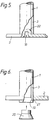
- Figure 5 shows another embodiment.
- the resistor rod 1 which can be left unbevelled.
- a pressing force is applied to the base plate 2 on a circular region, the diameter of which approximately corresponds to the internal diameter of the resistor rod 1, being slightly larger than said internal diameter.
- a cylindrical boss 18 with a desired height on the surface of the plate 2.
- the resistor rod 1 may be pressed onto the boss 18, which penetrates into the resistor rod 1 and is tightly frictionally secured to its internal wall.
- Figure 6 shows a third embodiment of the filter, in which the resonator rod 1 comprises a bevelled surface 19 inside the end of the rod 1, whereby a tapering point region 21 is formed between the bevelled surface and the outer wall of the resonator rod 1.
- the base plate 2 is provided with a hole, formed so as to slidably receive the rod and in which the resonator rod 1 is inserted so that the point region will extend slightly through the bottom surface of the base plate 2.
- the filters can be manufactured in a single work stage. Also preliminary tuning can be carried out by varying the length of the resonator rod 1 with respect to the base plate 2.
Landscapes
- Physics & Mathematics (AREA)
- Electromagnetism (AREA)
- Control Of Motors That Do Not Use Commutators (AREA)
Applications Claiming Priority (2)
| Application Number | Priority Date | Filing Date | Title |
|---|---|---|---|
| FI914390 | 1991-09-18 | ||
| FI914390A FI89115C (fi) | 1991-09-18 | 1991-09-18 | Foerfarande foer faestandet av en resonatorstav mot ett hoegfrekvensfilters vaegg och hoegfrekvensfilter |
Publications (2)
| Publication Number | Publication Date |
|---|---|
| EP0533394A2 true EP0533394A2 (fr) | 1993-03-24 |
| EP0533394A3 EP0533394A3 (en) | 1994-06-01 |
Family
ID=8533152
Family Applications (1)
| Application Number | Title | Priority Date | Filing Date |
|---|---|---|---|
| EP19920308214 Withdrawn EP0533394A3 (en) | 1991-09-18 | 1992-09-10 | Filter comprising a resonator rod mounted on a base plate |
Country Status (2)
| Country | Link |
|---|---|
| EP (1) | EP0533394A3 (fr) |
| FI (1) | FI89115C (fr) |
Cited By (6)
| Publication number | Priority date | Publication date | Assignee | Title |
|---|---|---|---|---|
| US6114928A (en) * | 1997-11-10 | 2000-09-05 | Smith; Patrick | Mounting assemblies for tubular members used in RF filters |
| EP1111709A1 (fr) * | 1999-12-01 | 2001-06-27 | ADC Telecommunications Oy | Procédé de montage d'un conducteur à l'intérieur d'une cavité résonante et conducteur à l'intérieur d'une cavité résonante |
| EP1107350A3 (fr) * | 1999-12-01 | 2002-09-11 | ADC Telecommunications Oy | Procédé et dispositif pour la fixation d' un conducteur interne d'une structure de résonateur |
| US6593832B2 (en) * | 2000-03-30 | 2003-07-15 | Allgon Ab | Coaxial cavity resonator, filter and use of resonator component in a filter |
| US7096565B2 (en) | 2003-06-19 | 2006-08-29 | Powerwave Technologies, Inc. | Flanged inner conductor coaxial resonators |
| CN107248602A (zh) * | 2017-04-19 | 2017-10-13 | 东莞洲亮通讯科技有限公司 | 谐振柱安装系统 |
Family Cites Families (3)
| Publication number | Priority date | Publication date | Assignee | Title |
|---|---|---|---|---|
| US4112398A (en) * | 1976-08-05 | 1978-09-05 | Hughes Aircraft Company | Temperature compensated microwave filter |
| FR2477782A1 (fr) * | 1980-03-05 | 1981-09-11 | Thomson Csf | Dispositif d'accord en hyperfrequences, du type a contacts glissants, et filtre comportant un tel dispositif |
| US4736173A (en) * | 1983-06-30 | 1988-04-05 | Hughes Aircraft Company | Thermally-compensated microwave resonator utilizing current-null segmentation |
-
1991
- 1991-09-18 FI FI914390A patent/FI89115C/fi not_active IP Right Cessation
-
1992
- 1992-09-10 EP EP19920308214 patent/EP0533394A3/en not_active Withdrawn
Cited By (9)
| Publication number | Priority date | Publication date | Assignee | Title |
|---|---|---|---|---|
| US6114928A (en) * | 1997-11-10 | 2000-09-05 | Smith; Patrick | Mounting assemblies for tubular members used in RF filters |
| EP1111709A1 (fr) * | 1999-12-01 | 2001-06-27 | ADC Telecommunications Oy | Procédé de montage d'un conducteur à l'intérieur d'une cavité résonante et conducteur à l'intérieur d'une cavité résonante |
| EP1107350A3 (fr) * | 1999-12-01 | 2002-09-11 | ADC Telecommunications Oy | Procédé et dispositif pour la fixation d' un conducteur interne d'une structure de résonateur |
| US6501349B2 (en) * | 1999-12-01 | 2002-12-31 | Remec Oy | Method and arrangement for fastening inner conductor of resonator structure |
| US6614331B2 (en) | 1999-12-01 | 2003-09-02 | Remec Oy | Method of manufacturing inner conductor of resonator, and inner conductor of resonator |
| US6593832B2 (en) * | 2000-03-30 | 2003-07-15 | Allgon Ab | Coaxial cavity resonator, filter and use of resonator component in a filter |
| US7096565B2 (en) | 2003-06-19 | 2006-08-29 | Powerwave Technologies, Inc. | Flanged inner conductor coaxial resonators |
| US7644486B2 (en) | 2003-06-19 | 2010-01-12 | Powerwave Technologies, Inc. | Method of making a flanged body |
| CN107248602A (zh) * | 2017-04-19 | 2017-10-13 | 东莞洲亮通讯科技有限公司 | 谐振柱安装系统 |
Also Published As
| Publication number | Publication date |
|---|---|
| EP0533394A3 (en) | 1994-06-01 |
| FI89115B (fi) | 1993-04-30 |
| FI914390A0 (fi) | 1991-09-18 |
| FI89115C (fi) | 1993-08-10 |
Similar Documents
| Publication | Publication Date | Title |
|---|---|---|
| FI84674B (fi) | Helix-resonator. | |
| EP2656435A1 (fr) | Filtre haute fréquence syntonisable | |
| US6255922B1 (en) | Microwave resonator with dielectric tuning body resiliently secured to a movable rod by spring means | |
| GB2217921A (en) | A transmission line resonator | |
| US4034319A (en) | Coupled bar microwave bandpass filter | |
| US20150288043A1 (en) | Tunable high frequency filter | |
| EP0657954A2 (fr) | Filtre diélectrique amélioré à plusieurs cavités | |
| KR20190081916A (ko) | 플레이트 탄성체의 형상 변화를 이용한 rf 캐비티 필터 및 이의 제조 방법 | |
| US4630012A (en) | Ring shaped dielectric resonator with adjustable tuning screw extending upwardly into ring opening | |
| JP7239215B2 (ja) | 高周波フィルタの部品間の結合構造の形成方法 | |
| US6337611B1 (en) | Sleeve in a radio frequency filter | |
| FI89115C (fi) | Foerfarande foer faestandet av en resonatorstav mot ett hoegfrekvensfilters vaegg och hoegfrekvensfilter | |
| CN1353875A (zh) | 温度补偿杆式谐振器 | |
| US6118356A (en) | Microwave cavity having a removable end wall | |
| JP3385909B2 (ja) | フィルタ及び送受信器 | |
| US6593832B2 (en) | Coaxial cavity resonator, filter and use of resonator component in a filter | |
| KR102077476B1 (ko) | Pimd로 인한 성능 저하에 강인한rf 캐비티 필터 및 rf 캐비티 필터 제조 방법 | |
| CN106450616B (zh) | 射频腔体器件及其盖板、盖板的设计方法 | |
| US4365221A (en) | Helical resonator filter with dielectric apertures | |
| US8327520B2 (en) | Method for producing a coupling line | |
| JPH01260901A (ja) | 誘電体フィルタ | |
| EP1693919A1 (fr) | Réglage de resonateurs RF | |
| US20060255888A1 (en) | Radio-frequency filter | |
| CN2337681Y (zh) | 矩形腔组合式滤波器 | |
| US20060135092A1 (en) | Radio frequency filter |
Legal Events
| Date | Code | Title | Description |
|---|---|---|---|
| PUAI | Public reference made under article 153(3) epc to a published international application that has entered the european phase |
Free format text: ORIGINAL CODE: 0009012 |
|
| AK | Designated contracting states |
Kind code of ref document: A2 Designated state(s): DE DK FR GB |
|
| PUAL | Search report despatched |
Free format text: ORIGINAL CODE: 0009013 |
|
| AK | Designated contracting states |
Kind code of ref document: A3 Designated state(s): DE DK FR GB |
|
| 17P | Request for examination filed |
Effective date: 19941201 |
|
| 17Q | First examination report despatched |
Effective date: 19960724 |
|
| 18W | Application withdrawn |
Withdrawal date: 19961029 |