EP0533496A1 - Connecteur avec une pince de décharge de traction montrant dans une direction variable - Google Patents
Connecteur avec une pince de décharge de traction montrant dans une direction variable Download PDFInfo
- Publication number
- EP0533496A1 EP0533496A1 EP92308544A EP92308544A EP0533496A1 EP 0533496 A1 EP0533496 A1 EP 0533496A1 EP 92308544 A EP92308544 A EP 92308544A EP 92308544 A EP92308544 A EP 92308544A EP 0533496 A1 EP0533496 A1 EP 0533496A1
- Authority
- EP
- European Patent Office
- Prior art keywords
- fixture
- strain relief
- housing
- fiber
- cable
- Prior art date
- Legal status (The legal status is an assumption and is not a legal conclusion. Google has not performed a legal analysis and makes no representation as to the accuracy of the status listed.)
- Ceased
Links
Images

Classifications
-
- G—PHYSICS
- G02—OPTICS
- G02B—OPTICAL ELEMENTS, SYSTEMS OR APPARATUS
- G02B6/00—Light guides; Structural details of arrangements comprising light guides and other optical elements, e.g. couplings
- G02B6/24—Coupling light guides
- G02B6/36—Mechanical coupling means
- G02B6/38—Mechanical coupling means having fibre to fibre mating means
- G02B6/3807—Dismountable connectors, i.e. comprising plugs
- G02B6/381—Dismountable connectors, i.e. comprising plugs of the ferrule type, e.g. fibre ends embedded in ferrules, connecting a pair of fibres
- G02B6/3826—Dismountable connectors, i.e. comprising plugs of the ferrule type, e.g. fibre ends embedded in ferrules, connecting a pair of fibres characterised by form or shape
- G02B6/3829—Bent or angled connectors
-
- G—PHYSICS
- G02—OPTICS
- G02B—OPTICAL ELEMENTS, SYSTEMS OR APPARATUS
- G02B6/00—Light guides; Structural details of arrangements comprising light guides and other optical elements, e.g. couplings
- G02B6/24—Coupling light guides
- G02B6/36—Mechanical coupling means
- G02B6/38—Mechanical coupling means having fibre to fibre mating means
- G02B6/3807—Dismountable connectors, i.e. comprising plugs
- G02B6/3833—Details of mounting fibres in ferrules; Assembly methods; Manufacture
- G02B6/3847—Details of mounting fibres in ferrules; Assembly methods; Manufacture with means preventing fibre end damage, e.g. recessed fibre surfaces
-
- G—PHYSICS
- G02—OPTICS
- G02B—OPTICAL ELEMENTS, SYSTEMS OR APPARATUS
- G02B6/00—Light guides; Structural details of arrangements comprising light guides and other optical elements, e.g. couplings
- G02B6/24—Coupling light guides
- G02B6/36—Mechanical coupling means
- G02B6/38—Mechanical coupling means having fibre to fibre mating means
- G02B6/3807—Dismountable connectors, i.e. comprising plugs
- G02B6/3869—Mounting ferrules to connector body, i.e. plugs
- G02B6/387—Connector plugs comprising two complementary members, e.g. shells, caps, covers, locked together
-
- G—PHYSICS
- G02—OPTICS
- G02B—OPTICAL ELEMENTS, SYSTEMS OR APPARATUS
- G02B6/00—Light guides; Structural details of arrangements comprising light guides and other optical elements, e.g. couplings
- G02B6/24—Coupling light guides
- G02B6/36—Mechanical coupling means
- G02B6/38—Mechanical coupling means having fibre to fibre mating means
- G02B6/3807—Dismountable connectors, i.e. comprising plugs
- G02B6/3873—Connectors using guide surfaces for aligning ferrule ends, e.g. tubes, sleeves, V-grooves, rods, pins, balls
- G02B6/3874—Connectors using guide surfaces for aligning ferrule ends, e.g. tubes, sleeves, V-grooves, rods, pins, balls using tubes, sleeves to align ferrules
- G02B6/3878—Connectors using guide surfaces for aligning ferrule ends, e.g. tubes, sleeves, V-grooves, rods, pins, balls using tubes, sleeves to align ferrules comprising a plurality of ferrules, branching and break-out means
-
- G—PHYSICS
- G02—OPTICS
- G02B—OPTICAL ELEMENTS, SYSTEMS OR APPARATUS
- G02B6/00—Light guides; Structural details of arrangements comprising light guides and other optical elements, e.g. couplings
- G02B6/24—Coupling light guides
- G02B6/36—Mechanical coupling means
- G02B6/38—Mechanical coupling means having fibre to fibre mating means
- G02B6/3807—Dismountable connectors, i.e. comprising plugs
- G02B6/3887—Anchoring optical cables to connector housings, e.g. strain relief features
- G02B6/38875—Protection from bending or twisting
-
- G—PHYSICS
- G02—OPTICS
- G02B—OPTICAL ELEMENTS, SYSTEMS OR APPARATUS
- G02B6/00—Light guides; Structural details of arrangements comprising light guides and other optical elements, e.g. couplings
- G02B6/44—Mechanical structures for providing tensile strength and external protection for fibres, e.g. optical transmission cables
- G02B6/4439—Auxiliary devices
- G02B6/4471—Terminating devices ; Cable clamps
- G02B6/4478—Bending relief means
-
- G—PHYSICS
- G02—OPTICS
- G02B—OPTICAL ELEMENTS, SYSTEMS OR APPARATUS
- G02B6/00—Light guides; Structural details of arrangements comprising light guides and other optical elements, e.g. couplings
- G02B6/24—Coupling light guides
- G02B6/36—Mechanical coupling means
- G02B6/38—Mechanical coupling means having fibre to fibre mating means
- G02B6/3807—Dismountable connectors, i.e. comprising plugs
- G02B6/389—Dismountable connectors, i.e. comprising plugs characterised by the method of fastening connecting plugs and sockets, e.g. screw- or nut-lock, snap-in, bayonet type
- G02B6/3893—Push-pull type, e.g. snap-in, push-on
Definitions
- the specification relates to a fiber optic connector with a strain relief for an optical fiber cable.
- a fiber optic connector disclosed in EP application 90200113.0, publication number 0,374,136 comprises, two mating housing halves that interlock, and the rear ends of the housing halves close over a flexible strain relief that encircles an optical fiber cable.
- the strain relief can bend along an arc to bend the cable along a corresponding arc.
- a bend in the optical fibers of the cable causes attenuation of an optical signal being transmitted along the fibers.
- Such signal attenuation or weakening is referred to as being caused by optical bend losses.
- Care is required to prevent a severe bend in any optical fiber in the cable, such a bend being described as severe if such a bend exceeds a minimum bend radius of curvature that would cause undesired attenuation of an optical signal transmitted along the fiber.
- a severe bend is avoided in the known connector by extending a front of the cable straight from the connector, and passing the cable along a straight front portion of the strain relief before allowing the cable to bend in an arc that begins in a rearward
- a feature of the invention resides in a fiber optic connector for an optical fiber cable, and a fixture for holding a strain relief for the cable that points the strain relief and the cable angularly from the connector.
- Another feature of the invention resides in a fiber optic connector for an optical fiber cable, and a fixture for mounting a strain relief in various angular positions relative to the connector.
- a further feature of the invention resides in a fiber optic connector for an optical fiber cable, and an angularly extending fixture for angularly pointing the cable relative to the housing, and an optical fiber of the cable extending within the fixture, and being free to assume a stress relieving shape within the fixture to avoid a severe bend in the fiber.
- a further feature of the invention resides in a fiber optic connector for an optical fiber cable, comprising; a strain relief encircling an optical fiber cable, at least one optical fiber projecting from the strain relief, a housing enclosing the fiber, and a fixture attached to the strain relief, the fixture interlocking to the housing at a stationary position angularly pointing the strain relief and the cable relative to the housing, and the fiber extending within the fixture, and being free to assume a stress relieving shape within the fixture to avoid a severe bend in the fiber.
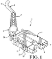
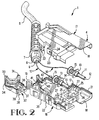
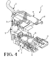
- a fiber optic connector 1 for an optical fiber cable 2 comprises; a strain relief 3 encircling the cable 2, a housing 4 and a fixture 5 attached to the strain relief 3, the fixture 5 interlocking with the housing 4 at a stationary position angularly pointing the strain relief 3 and the cable 2 relative to the housing 4. Further details of the strain relief 3 and of the housing 4 are disclosed in EP Application 90200113.0.
- the cable 2 includes an outer jacket 6 directly received in a tubular, flexible portion of the strain relief 3.
- a radially projecting external flange 7 is near a front end 8 of the strain relief 3.
- the front end 8 of the strain relief 3 is attached to a front end 9 of the jacket 6 of the cable 2.
- the cable 2 includes at least one corresponding optical fiber 10 projecting outward from the front end 9 of the jacket 6 of the cable 2.
- two corresponding optical fibers 10 are disclosed.
- Each corresponding optical fiber 10 is covered by a known flexible buffer.
- reference to an optical fiber 10 applies to a buffer covered optical fiber 10, as well as to a bare optical fiber 10, not shown.
- a holder 11 comprising a ferrule surrounds each corresponding optical fiber 10 of the cable 2.
- the corresponding optical fiber 10 is polished on its end with an optical face 12 that is flush with a front end of the holder 11.
- a coil spring 13 encircles a corresponding holder 11, and is compressible between a flange 14 on the corresponding holder 11 and a reciprocating washer 15 slidably received over a corresponding holder 11 to the rear of the spring 13.
- the housing 4 comprises two mating housing halves 16, 17 that interlock to each other.
- Each housing half 16 or 17 is of unitary construction, for example of molded plastic.
- the housing 4 has a front, mating end 18, a rear end 19 and two sides 20, 21 divided by the housing halves 16, 17.
- On each side 20, 21 of each housing half 16, 17 is a slotted hasp 22 that extends toward the other housing half 16, 17.
- On each side 20, 21 of each housing half 16, 17 is a projecting, wedge shaped lug 23 with a locking surface 24.
- each housing half 16, 17 has a corresponding interior recess 25 corresponding to each holder 11 for a corresponding optical fiber 10.
- Each corresponding holder 11 is surrounded partially by the recess 25 of each housing half 16, 17, and aligns the optical face 12 of the corresponding fiber 10 at a mating end 18 of the housing 4.
- the housing halves 16, 17 divide the mating end 18.
- the flange 14 of the corresponding holder 11 and the washer 15 of the holder 11 are received between a front wall 26 and a rear wall 27 of each housing half 16, 17.
- the holder 11 When pressure is applied to a front end of the holder 11, the holder 11 will move rearward, and the coil spring 13 will be compressed between the flange 14 and the washer 15.
- the coil spring 13 will expand to move the holder 11 forward.
- Each housing half 16, 17 has a hollow interior between the sides 20, 21.
- the housing halves 16, 17 interlock with each other, they form the housing 4 that is hollow and loosely surrounds each corresponding optical fiber 10 projecting from the jacket 6 and the strain relief 3 to the holder 11.
- a feature of the invention resides in the fixture 5 for holding the strain relief 3.
- the fixture 5 comprises two mating fixture halves 28, 29, Figures 2 and 5, that divide the fixture 5 into two parts, and that interlock with each other to form the fixture 5.
- the fixture halves 28, 29 are joined together by a deformable web 30, Figure 5, that bends to allow the fixture halves 28, 29 to mate to each other.
- Each fixture half 28 or 29 angularly extends from a rear end 31 of the fixture 5 to a front end 32.
- a circumferential groove 33 of the fixture 5 is near the rear end 30 fits over the flange 14 of the strain relief 3.
- the fixture halves 28, 29 divide the rear end 30 and the groove 33.
- the flange 14 of the strain relief 3 is secured in the groove 33.
- the flange 14 is oblong, and the groove 33 matches the shape of the flange 14, to interlock with the strain relief 3 and to resist rotation of the strain relief 3 relative to the fixture 5.
- the fixture 5 formed by the interlocked fixture halves 28, 29 surrounds a front end of, and interlocks with, the strain relief 3.
- the fixture 5 covers and loosely surrounds the corresponding optical fiber 10 extending from the cable 2 and from the strain relief 3.
- the housing 4 formed by the interlocked housing halves 16, 17 surrounds the corresponding optical fiber 10 projecting from the fixture 5 and extending to the corresponding holder 11.
- each corresponding fiber 10 is required to bend in an arc along the interior of the fixture 5.
- the fiber 10 does not necessarily extend concentrically along the elbow of the fixture 5. Instead, the fiber 10 extending within the fixture 5, is free to assume a shape within the fixture 5 to avoid a severe bend in the fiber 10. For example, to relieve bending stresses in the fiber 10, and to avoid a severe bend in the fiber 10, the fiber 10 assumes a smoothly curved arc that is relatively straighter than the minimum bend radius.
- the arc of the fiber 10 extends in and along the elbow of the fixture 5.
- the elbow of the fixture 5 has a more acute curvature than the arc of the fiber 10.
- the interior space of the fixture 5, particularly at the elbow, surrounding the fiber 10 is many times larger than the diameter of the fiber 10.
- the fiber 10 and its arc shape are not constrained to a severe arc by the elbow. Instead, the fiber 10 is free to extend in an arc that does not match the arc of the elbow.
- the fiber 10 may extend along the fixture 5 with a different arc than that of the elbow of the fixture 5.
- the fixture 5 has an outwardly bulged hollow portion 34 adjacent to the front end 8 of the strain relief 3.
- the arc of the fiber 10 may have an arc, so different in curvature than that of the elbow, to such an extent that the fiber 10 is caused to transverse in and along the bulged hollow portion 34.
- the fixture halves 28, 29 divide the bulged hollow portion 34 into two parts.
- a further feature of the invention resides in the fixture 5 being adapted for holding the strain relief 3 in an angular position relative to a longitudinal axis of the connector 1.
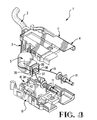
- the front end 32 of the fixture 5 is circumscribed by intersecting multiple sides 35, 36, 37, 38, Figure 3.
- An exterior groove 39 is recessed in the sides 34, 35, 36, 37 and continuously circumscribes the exterior of the fixture 5.
- the fixture halves 28, 29 divide the front end 32 of the fixture 5 into two parts.
- a rear wall 40 of the housing 4 interlocks with the fixture 5.
- the rear wall 37 has an opening 41 that receives the front end 32 of the fixture 5.
- the housing halves 16, 17 divide the rear wall 40 and the opening 41 into two parts.
- the opening 40 has multiple intersecting side edges 42 that interlock with the groove 36 in the sides 35, 36, 37, 38 of the fixture 5 and prevent relative rotation of the fixture 5 and the housing 4. With relative rotation prevented, the fixture 5 angularly extends from the housing 4, and points the strain relief 3 at an angle with respect to the housing 4.
- the four multiple edges of the opening 40 symmetrically surround a central axis of the opening 40.
- the four multiple sides 35, 36, 37, 38 of the fixture 5 symmetrically surround a central axis of the opening 40.
- the four multiple sides 35, 36, 37, 38 of the fixture 5 symmetrically surround a central axis of the front end 32.
- the fixture 5 fits within the opening 41 of the housing 4 to prevent relative rotation therebetween.
- the angular direction of the fixture 5 in each of its positions points the strain relief 3 angularly in a different direction with respect to the housing 4.
- the fixture 5 adapts a strain relief 3 for an optical fiber cable 2 to extend from a fiber optic connector 1 in any one of a number of directions without causing a severe bend in a corresponding optical fiber 10 of the cable 2.
Landscapes
- Physics & Mathematics (AREA)
- General Physics & Mathematics (AREA)
- Optics & Photonics (AREA)
- Mechanical Coupling Of Light Guides (AREA)
Applications Claiming Priority (2)
| Application Number | Priority Date | Filing Date | Title |
|---|---|---|---|
| US07/763,108 US5138678A (en) | 1991-09-20 | 1991-09-20 | Connector with a variable direction strain relief |
| US763108 | 1991-09-20 |
Publications (1)
| Publication Number | Publication Date |
|---|---|
| EP0533496A1 true EP0533496A1 (fr) | 1993-03-24 |
Family
ID=25066902
Family Applications (1)
| Application Number | Title | Priority Date | Filing Date |
|---|---|---|---|
| EP92308544A Ceased EP0533496A1 (fr) | 1991-09-20 | 1992-09-18 | Connecteur avec une pince de décharge de traction montrant dans une direction variable |
Country Status (3)
| Country | Link |
|---|---|
| US (1) | US5138678A (fr) |
| EP (1) | EP0533496A1 (fr) |
| JP (1) | JPH05224090A (fr) |
Cited By (8)
| Publication number | Priority date | Publication date | Assignee | Title |
|---|---|---|---|---|
| EP0677756A3 (fr) * | 1994-04-13 | 1996-05-01 | Framatome Connectors Int | Connecteur à fibre pour câble hybride optique et métallique. |
| EP0859252A3 (fr) * | 1997-02-12 | 1998-10-07 | The Whitaker Corporation | Manchon amélioré de soulagement de contraintes pour câble |
| EP0831348A3 (fr) * | 1996-09-24 | 2000-02-02 | SUMITOMO WIRING SYSTEMS, Ltd. | Connecteur optique |
| EP1091223A3 (fr) * | 1999-08-05 | 2001-06-20 | Yazaki Corporation | Connecteur optique et procédé d'assemblage d'une prise optique |
| AT407927B (de) * | 1994-12-05 | 2001-07-25 | Framatome Connectors Int | Kombinierter lichtwellenleiter-/metallkabel- steckverbinder |
| DE10020675A1 (de) * | 2000-04-27 | 2001-10-31 | Delphi Tech Inc | Verbindungsmodul |
| WO2004107000A3 (fr) * | 2003-05-22 | 2005-05-26 | 3M Innovative Properties Co | Gaine de retenue anti-traction a extension souple permettant de guider un cable fibre optique |
| EP1412785A4 (fr) * | 2001-06-26 | 2005-07-20 | Viasystems Group Inc | Cintrage d'une fibre optique dans un plan arriere |
Families Citing this family (84)
| Publication number | Priority date | Publication date | Assignee | Title |
|---|---|---|---|---|
| US5347603A (en) * | 1993-06-14 | 1994-09-13 | Molex Incorporated | Right angle cable strain relief |
| US5390272A (en) * | 1993-08-31 | 1995-02-14 | Amphenol Corporation | Fiber optic cable connector with strain relief boot |
| USRE40150E1 (en) | 1994-04-25 | 2008-03-11 | Matsushita Electric Industrial Co., Ltd. | Fiber optic module |
| US5481634A (en) * | 1994-06-24 | 1996-01-02 | At&T Corp. | Connector for optical fiber |
| US5461690A (en) * | 1994-07-29 | 1995-10-24 | At&T Ipm Corp. | Bend-limiting apparatus for a cable |
| US5717533A (en) | 1995-01-13 | 1998-02-10 | Methode Electronics Inc. | Removable optoelectronic module |
| US6220878B1 (en) | 1995-10-04 | 2001-04-24 | Methode Electronics, Inc. | Optoelectronic module with grounding means |
| DE19507669C2 (de) * | 1995-03-06 | 1998-10-08 | Telegaertner Geraetebau Gmbh | Optischer Mehrfach-Steckverbinder, insbesondere für Rund- oder Zip-cord-Kabel |
| US5710851A (en) * | 1995-11-06 | 1998-01-20 | Amphenol Corporation | Strain relief system for a fiber optic connector |
| US5676568A (en) * | 1996-03-28 | 1997-10-14 | Belden Wire & Cable Company | Variable entry connector |
| US5933557A (en) * | 1996-11-19 | 1999-08-03 | Siecor Corporation | Multi-link boot assembly for cable connector |
| US6017154A (en) * | 1998-02-05 | 2000-01-25 | Lucent Technologies, Inc. | Optical fiber connector with cable anchoring means |
| US6024498A (en) * | 1998-02-05 | 2000-02-15 | Lucent Technologies Inc. | Optical fiber connector assembly |
| US6130983A (en) * | 1998-12-23 | 2000-10-10 | Cheng; Yu-Feng | Rotatable L-shaped fiber optic connector |
| US6201908B1 (en) * | 1999-07-02 | 2001-03-13 | Blaze Network Products, Inc. | Optical wavelength division multiplexer/demultiplexer having preformed passively aligned optics |
| US6220873B1 (en) | 1999-08-10 | 2001-04-24 | Stratos Lightwave, Inc. | Modified contact traces for interface converter |
| US6695486B1 (en) | 1999-10-29 | 2004-02-24 | Cisco Technology, Inc | Angled fiber optic connector |
| US6647198B2 (en) * | 2000-07-14 | 2003-11-11 | Semco Machine Corporation | Apparatus for housing fiber optic modules |
| US6338645B1 (en) | 2000-07-28 | 2002-01-15 | Apple Computer, Inc. | Connector having a cable that is relatively moveable about an axis |
| JP2002203645A (ja) | 2000-12-27 | 2002-07-19 | Nagano Fujitsu Component Kk | ケーブルコネクタ |
| US6676300B2 (en) * | 2001-01-25 | 2004-01-13 | Sumitomo Electric Industries, Ltd. | Ferrule for optical connector and making method thereof |
| US6964525B2 (en) * | 2001-01-25 | 2005-11-15 | Sumitomo Electric Industries, Ltd. | Optical connector and backplane assembly |
| US6942395B1 (en) | 2001-01-29 | 2005-09-13 | Jds Uniphase Corporation | Method and apparatus of pull-lever release for fiber optic modules |
| US6692159B2 (en) | 2001-04-14 | 2004-02-17 | E20 Communications, Inc. | De-latching mechanisms for fiber optic modules |
| US6851867B2 (en) | 2001-04-14 | 2005-02-08 | Jds Uniphase Corporation | Cam-follower release mechanism for fiber optic modules with side delatching mechanisms |
| US6994478B1 (en) | 2001-04-14 | 2006-02-07 | Jds Uniphase Corporation | Modules having rotatable release and removal lever |
| US6796715B2 (en) | 2001-04-14 | 2004-09-28 | E20 Communications, Inc. | Fiber optic modules with pull-action de-latching mechanisms |
| US6840680B1 (en) | 2001-04-14 | 2005-01-11 | Jds Uniphase Corporation | Retention and release mechanisms for fiber optic modules |
| US6863448B2 (en) | 2001-04-14 | 2005-03-08 | Jds Uniphase Corporation | Method and apparatus for push button release fiber optic modules |
| US6601997B2 (en) | 2001-04-17 | 2003-08-05 | Fci Americas Technology, Inc. | Fiber optic cable guide boot |
| JP2002341182A (ja) * | 2001-05-14 | 2002-11-27 | Auto Network Gijutsu Kenkyusho:Kk | 光コネクタ |
| US6734435B2 (en) * | 2001-05-29 | 2004-05-11 | Rae Systems, Inc. | Photo-ionization detector and method for continuous operation and real-time self-cleaning |
| US6629783B2 (en) | 2001-07-06 | 2003-10-07 | Fci Americas Technology, Inc. | Fiber optic cable guide boot |
| US7118281B2 (en) | 2002-08-09 | 2006-10-10 | Jds Uniphase Corporation | Retention and release mechanisms for fiber optic modules |
| US6817780B2 (en) * | 2003-01-15 | 2004-11-16 | Fci Americas Technology, Inc. | Guide boot for a fiber-optic cable |
| US7695197B2 (en) * | 2006-04-20 | 2010-04-13 | Tyco Electronics Corporation | Bend limiter |
| US20080124032A1 (en) * | 2006-04-28 | 2008-05-29 | Christopher Horvath | System and Method of Protecting Optical Cables |
| US7670190B2 (en) * | 2008-07-08 | 2010-03-02 | Hon Hai Precision Ind. Co., Ltd. | Rotatable electrical interconnection device |
| US11294136B2 (en) | 2008-08-29 | 2022-04-05 | Corning Optical Communications LLC | High density and bandwidth fiber optic apparatuses and related equipment and methods |
| US8452148B2 (en) | 2008-08-29 | 2013-05-28 | Corning Cable Systems Llc | Independently translatable modules and fiber optic equipment trays in fiber optic equipment |
| EP2221932B1 (fr) * | 2009-02-24 | 2011-11-16 | CCS Technology Inc. | Dispositif de maintien pour câble ou ensemble à utiliser avec un câble |
| US8699838B2 (en) | 2009-05-14 | 2014-04-15 | Ccs Technology, Inc. | Fiber optic furcation module |
| US9075216B2 (en) | 2009-05-21 | 2015-07-07 | Corning Cable Systems Llc | Fiber optic housings configured to accommodate fiber optic modules/cassettes and fiber optic panels, and related components and methods |
| US8712206B2 (en) * | 2009-06-19 | 2014-04-29 | Corning Cable Systems Llc | High-density fiber optic modules and module housings and related equipment |
| EP2443501A1 (fr) * | 2009-06-19 | 2012-04-25 | Corning Cable Systems LLC | Appareil d'infrastructure à connexion en fibre optique haute capacité |
| CN106918885B (zh) | 2009-06-19 | 2021-09-21 | 康宁光缆系统有限责任公司 | 高密度和带宽光纤装置以及相关设备和方法 |
| US20110129185A1 (en) * | 2009-11-30 | 2011-06-02 | Lewallen C Paul | Articulated Strain Relief Boot on a Fiber Optic Module and Associated Methods |
| EP2333597B1 (fr) * | 2009-11-30 | 2016-09-21 | Corning Optical Communications LLC | Ensemble de module à fibres optiques et procédés associés |
| US8625950B2 (en) * | 2009-12-18 | 2014-01-07 | Corning Cable Systems Llc | Rotary locking apparatus for fiber optic equipment trays and related methods |
| US8593828B2 (en) * | 2010-02-04 | 2013-11-26 | Corning Cable Systems Llc | Communications equipment housings, assemblies, and related alignment features and methods |
| US8913866B2 (en) | 2010-03-26 | 2014-12-16 | Corning Cable Systems Llc | Movable adapter panel |
| CN102214859A (zh) * | 2010-04-07 | 2011-10-12 | 富士康(昆山)电脑接插件有限公司 | 线缆连接组件 |
| AU2011265751B2 (en) | 2010-04-16 | 2015-09-10 | Corning Optical Communications LLC | Sealing and strain relief device for data cables |
| US9519118B2 (en) | 2010-04-30 | 2016-12-13 | Corning Optical Communications LLC | Removable fiber management sections for fiber optic housings, and related components and methods |
| US8879881B2 (en) | 2010-04-30 | 2014-11-04 | Corning Cable Systems Llc | Rotatable routing guide and assembly |
| US9075217B2 (en) | 2010-04-30 | 2015-07-07 | Corning Cable Systems Llc | Apparatuses and related components and methods for expanding capacity of fiber optic housings |
| US9632270B2 (en) | 2010-04-30 | 2017-04-25 | Corning Optical Communications LLC | Fiber optic housings configured for tool-less assembly, and related components and methods |
| US8660397B2 (en) | 2010-04-30 | 2014-02-25 | Corning Cable Systems Llc | Multi-layer module |
| US9720195B2 (en) | 2010-04-30 | 2017-08-01 | Corning Optical Communications LLC | Apparatuses and related components and methods for attachment and release of fiber optic housings to and from an equipment rack |
| US8705926B2 (en) | 2010-04-30 | 2014-04-22 | Corning Optical Communications LLC | Fiber optic housings having a removable top, and related components and methods |
| JP5599237B2 (ja) * | 2010-06-23 | 2014-10-01 | 矢崎総業株式会社 | 光コネクタ |
| US8718436B2 (en) | 2010-08-30 | 2014-05-06 | Corning Cable Systems Llc | Methods, apparatuses for providing secure fiber optic connections |
| US9279951B2 (en) | 2010-10-27 | 2016-03-08 | Corning Cable Systems Llc | Fiber optic module for limited space applications having a partially sealed module sub-assembly |
| US8662760B2 (en) | 2010-10-29 | 2014-03-04 | Corning Cable Systems Llc | Fiber optic connector employing optical fiber guide member |
| US9116324B2 (en) | 2010-10-29 | 2015-08-25 | Corning Cable Systems Llc | Stacked fiber optic modules and fiber optic equipment configured to support stacked fiber optic modules |
| EP2646867B1 (fr) | 2010-11-30 | 2018-02-21 | Corning Optical Communications LLC | Support de corps de fibre et dispositif de réduction des tensions |
| US8622481B2 (en) | 2011-01-25 | 2014-01-07 | Joy Mm Delaware, Inc. | Fiber optic cable protection in a mining system |
| WO2012106513A1 (fr) | 2011-02-02 | 2012-08-09 | Corning Cable Systems Llc | Connecteurs de fibres optiques denses à obturateur et ensembles connecteurs aptes à établir des liaisons optiques pour des fonds de paniers optiques dans des baies d'équipements |
| US9008485B2 (en) | 2011-05-09 | 2015-04-14 | Corning Cable Systems Llc | Attachment mechanisms employed to attach a rear housing section to a fiber optic housing, and related assemblies and methods |
| EP2523265B1 (fr) * | 2011-05-12 | 2014-07-16 | Delphi Technologies, Inc. | Dispositif de décharge de traction / protection contre le pliage |
| CA2840388C (fr) | 2011-06-30 | 2020-03-10 | Corning Cable Systems Llc | Ensembles d'equipement a fibres optiques utilisant des boitiers hors dimensions de largeur u, et procedes associes |
| US8953924B2 (en) | 2011-09-02 | 2015-02-10 | Corning Cable Systems Llc | Removable strain relief brackets for securing fiber optic cables and/or optical fibers to fiber optic equipment, and related assemblies and methods |
| US9038832B2 (en) | 2011-11-30 | 2015-05-26 | Corning Cable Systems Llc | Adapter panel support assembly |
| CA2866245C (fr) * | 2012-03-08 | 2021-10-12 | Steven James MAAS | Station de detecteur, systeme et procede de detection de parametres sismiques |
| CA3118864C (fr) | 2012-03-08 | 2022-11-29 | Shell Internationale Research Maatschappij B.V. | Systeme integre de surveillance sismique et procede |
| US9250409B2 (en) | 2012-07-02 | 2016-02-02 | Corning Cable Systems Llc | Fiber-optic-module trays and drawers for fiber-optic equipment |
| US9042702B2 (en) | 2012-09-18 | 2015-05-26 | Corning Cable Systems Llc | Platforms and systems for fiber optic cable attachment |
| WO2014047651A2 (fr) * | 2012-09-24 | 2014-03-27 | Invuity, Inc. | Procédés et appareil pour régler les propriétés optiques de la lumière |
| EP2725397B1 (fr) | 2012-10-26 | 2015-07-29 | CCS Technology, Inc. | Unité de gestion de fibres optiques et dispositif de distribution de fibres optiques |
| US8985862B2 (en) | 2013-02-28 | 2015-03-24 | Corning Cable Systems Llc | High-density multi-fiber adapter housings |
| JP6244775B2 (ja) * | 2013-09-24 | 2017-12-13 | オムロン株式会社 | 光ファイバセンサ用光ファイバユニット |
| JP5695774B1 (ja) * | 2014-03-20 | 2015-04-08 | 株式会社フジクラ | 光コネクタおよび保護チューブの引き留め方法 |
| PT3245544T (pt) * | 2015-01-12 | 2026-05-27 | Afl Telecommunications Llc | Caixa de terminao de fibra tica |
| US9720184B2 (en) | 2015-02-04 | 2017-08-01 | International Business Machines Corporation | Blind mating strain relieved optical fiber connector |
Citations (5)
| Publication number | Priority date | Publication date | Assignee | Title |
|---|---|---|---|---|
| US3711815A (en) * | 1971-06-24 | 1973-01-16 | Gen Connector | Tight angle multi-contact electrical connector |
| DE2920266A1 (de) * | 1978-05-24 | 1979-12-06 | Nat Res Dev | Lichtleitkabel-kupplungsstueck |
| EP0339876A1 (fr) * | 1988-04-25 | 1989-11-02 | The Whitaker Corporation | Montage de connecteur avec enveloppe de protection mobile |
| DE9017440U1 (de) * | 1990-12-24 | 1991-03-07 | Krupp Atlas Elektronik GmbH, 2800 Bremen | Mehrpoliger Verbindungsstecker für Lichtleiterkabel |
| US5037175A (en) * | 1990-06-11 | 1991-08-06 | Amp Incorporated | Clip for dressing of fiber optic cable within confined space |
Family Cites Families (7)
| Publication number | Priority date | Publication date | Assignee | Title |
|---|---|---|---|---|
| US3307137A (en) * | 1965-05-27 | 1967-02-28 | Mc Graw Edison Co | Conductor termination |
| US3819849A (en) * | 1972-05-10 | 1974-06-25 | Flexible Metal Hose Mfg Co | Electrical cable connecting device |
| US4167303A (en) * | 1977-07-28 | 1979-09-11 | Amp Incorporated | Light transmitting fiber cable connector |
| US4203004A (en) * | 1978-04-20 | 1980-05-13 | Belden Corporation | Strain relief |
| US4645295A (en) * | 1980-02-04 | 1987-02-24 | Allied Corporation | Fiber optic connector |
| JPH06100698B2 (ja) * | 1984-06-08 | 1994-12-12 | アンプ・インコ−ポレ−テッド | 光ファイバコネクタ組立体 |
| US5073044A (en) * | 1990-10-31 | 1991-12-17 | Amp Incorporated | Right angle strain relief for optical fiber connector |
-
1991
- 1991-09-20 US US07/763,108 patent/US5138678A/en not_active Expired - Fee Related
-
1992
- 1992-09-18 EP EP92308544A patent/EP0533496A1/fr not_active Ceased
- 1992-09-18 JP JP4273508A patent/JPH05224090A/ja active Pending
Patent Citations (5)
| Publication number | Priority date | Publication date | Assignee | Title |
|---|---|---|---|---|
| US3711815A (en) * | 1971-06-24 | 1973-01-16 | Gen Connector | Tight angle multi-contact electrical connector |
| DE2920266A1 (de) * | 1978-05-24 | 1979-12-06 | Nat Res Dev | Lichtleitkabel-kupplungsstueck |
| EP0339876A1 (fr) * | 1988-04-25 | 1989-11-02 | The Whitaker Corporation | Montage de connecteur avec enveloppe de protection mobile |
| US5037175A (en) * | 1990-06-11 | 1991-08-06 | Amp Incorporated | Clip for dressing of fiber optic cable within confined space |
| DE9017440U1 (de) * | 1990-12-24 | 1991-03-07 | Krupp Atlas Elektronik GmbH, 2800 Bremen | Mehrpoliger Verbindungsstecker für Lichtleiterkabel |
Cited By (14)
| Publication number | Priority date | Publication date | Assignee | Title |
|---|---|---|---|---|
| EP0677756A3 (fr) * | 1994-04-13 | 1996-05-01 | Framatome Connectors Int | Connecteur à fibre pour câble hybride optique et métallique. |
| AT407927B (de) * | 1994-12-05 | 2001-07-25 | Framatome Connectors Int | Kombinierter lichtwellenleiter-/metallkabel- steckverbinder |
| EP1255142A1 (fr) * | 1996-09-24 | 2002-11-06 | Sumitomo Wiring Systems, Ltd. | Connecteur optique et bague-soufflet pour celui-ci |
| EP0831348A3 (fr) * | 1996-09-24 | 2000-02-02 | SUMITOMO WIRING SYSTEMS, Ltd. | Connecteur optique |
| EP0859252A3 (fr) * | 1997-02-12 | 1998-10-07 | The Whitaker Corporation | Manchon amélioré de soulagement de contraintes pour câble |
| EP1091223A3 (fr) * | 1999-08-05 | 2001-06-20 | Yazaki Corporation | Connecteur optique et procédé d'assemblage d'une prise optique |
| US6663292B1 (en) | 1999-08-05 | 2003-12-16 | Yazaki Corporation | Optical connector and an assembly method of optical plug |
| DE10020675A1 (de) * | 2000-04-27 | 2001-10-31 | Delphi Tech Inc | Verbindungsmodul |
| EP1412785A4 (fr) * | 2001-06-26 | 2005-07-20 | Viasystems Group Inc | Cintrage d'une fibre optique dans un plan arriere |
| US7095939B2 (en) | 2001-06-26 | 2006-08-22 | Tourne Joseph A A M | Bending an optical fiber into a backplane |
| US7187839B2 (en) | 2001-06-26 | 2007-03-06 | Tourne Joseph A A M | Bending an optical fiber into a backplane |
| US7428364B2 (en) | 2001-06-26 | 2008-09-23 | Tourne Joseph A A M | Bending an optical fiber into a backplane |
| WO2004107000A3 (fr) * | 2003-05-22 | 2005-05-26 | 3M Innovative Properties Co | Gaine de retenue anti-traction a extension souple permettant de guider un cable fibre optique |
| US7001081B2 (en) | 2003-05-22 | 2006-02-21 | 3M Innovative Properties Company | Strain relief boot with flexible extension for guiding fiber optic cable |
Also Published As
| Publication number | Publication date |
|---|---|
| US5138678A (en) | 1992-08-11 |
| JPH05224090A (ja) | 1993-09-03 |
Similar Documents
| Publication | Publication Date | Title |
|---|---|---|
| US5138678A (en) | Connector with a variable direction strain relief | |
| EP0629887B1 (fr) | Décharge de traction à angle droit pour des câbles | |
| EP0486064B1 (fr) | Décharge de traction emboîtable | |
| US4826277A (en) | Transition of a multiple fiber cable to single fiber cable | |
| US5781681A (en) | Bend limiting strain relief boot | |
| US5073044A (en) | Right angle strain relief for optical fiber connector | |
| US5271382A (en) | Bending device | |
| WO2004107000A3 (fr) | Gaine de retenue anti-traction a extension souple permettant de guider un cable fibre optique | |
| US6554489B2 (en) | Fiber optic cable guide and method of application | |
| EP0260774B1 (fr) | Décharge de contrainte pour connecteur à fibre optique | |
| EP0997756A2 (fr) | Guide pour cable à fibre optique | |
| US20210191060A1 (en) | Flexible boot with replaceable repositioning device therein | |
| CA2151071A1 (fr) | Appareil limiteur de pliage pour cable | |
| US6496642B2 (en) | Optical fiber cable routing guide | |
| US6899468B2 (en) | Optical fiber connectors | |
| EP2127589A1 (fr) | Endoscope | |
| JP3590539B2 (ja) | 内視鏡の光学繊維束 | |
| US6893165B2 (en) | Optic fiber connectors and coupling sleeve | |
| JPH10170755A (ja) | 光ファイバケーブル端末構造及びそれに使用されるキャップ部材 | |
| US9116307B2 (en) | Sleeve for optical connector, and optical connector | |
| US5028115A (en) | Connector for an optical waveguide | |
| US4793684A (en) | Arrangement for forming a strain-relief connection between an optical fibre cable and a coupling device | |
| JPS5860712A (ja) | ブ−ツ付プラグ | |
| US20100003002A1 (en) | Robust connector enforcement | |
| EP0188041B1 (fr) | Décharge de torsion réduite |
Legal Events
| Date | Code | Title | Description |
|---|---|---|---|
| PUAI | Public reference made under article 153(3) epc to a published international application that has entered the european phase |
Free format text: ORIGINAL CODE: 0009012 |
|
| AK | Designated contracting states |
Kind code of ref document: A1 Designated state(s): DE FR GB IT NL |
|
| 17P | Request for examination filed |
Effective date: 19930507 |
|
| 17Q | First examination report despatched |
Effective date: 19930917 |
|
| 18R | Application refused |
Effective date: 19961128 |