EP0533509A2 - Schnurlose Reihenanlage mit wiederholten Anrufversuchen für Stationen in durch Interferenz beeinflussten Zonen - Google Patents
Schnurlose Reihenanlage mit wiederholten Anrufversuchen für Stationen in durch Interferenz beeinflussten Zonen Download PDFInfo
- Publication number
- EP0533509A2 EP0533509A2 EP92308583A EP92308583A EP0533509A2 EP 0533509 A2 EP0533509 A2 EP 0533509A2 EP 92308583 A EP92308583 A EP 92308583A EP 92308583 A EP92308583 A EP 92308583A EP 0533509 A2 EP0533509 A2 EP 0533509A2
- Authority
- EP
- European Patent Office
- Prior art keywords
- signal
- cordless
- access unit
- channel
- unit
- Prior art date
- Legal status (The legal status is an assumption and is not a legal conclusion. Google has not performed a legal analysis and makes no representation as to the accuracy of the status listed.)
- Granted
Links
Images



Classifications
-
- H—ELECTRICITY
- H04—ELECTRIC COMMUNICATION TECHNIQUE
- H04W—WIRELESS COMMUNICATION NETWORKS
- H04W84/00—Network topologies
- H04W84/02—Hierarchically pre-organised networks, e.g. paging networks, cellular networks, WLAN [Wireless Local Area Network] or WLL [Wireless Local Loop]
- H04W84/10—Small scale networks; Flat hierarchical networks
- H04W84/16—WPBX [Wireless Private Branch Exchange]
-
- H—ELECTRICITY
- H04—ELECTRIC COMMUNICATION TECHNIQUE
- H04W—WIRELESS COMMUNICATION NETWORKS
- H04W68/00—User notification, e.g. alerting and paging, for incoming communication, change of service or the like
- H04W68/06—User notification, e.g. alerting and paging, for incoming communication, change of service or the like using multi-step notification by changing the notification area
Definitions
- the present invention relates generally to cordless telephone systems, and more specifically to a cordless key telephone system covering a plurality of service zones which may partially overlap, forming interference-affected zones due to the assignment of a single control channel to adjacent service zones.
- cordless key telephone systems comprise a main unit having first terminals connected to a public or local switched network and second terminals connected to access units located at strategic points of service zones. Each access unit exchanges call-processing signals over control channels with cordless stations and the main unit during call setup times and establishing a speech channel to a cordless station when entering a talking mode.
- the main unit includes a switch matrix for establishing a switched connection between the network and an appropriate access unit to link the cordless station to the network. During an idle state, each cordless station monitors the control channels assigned to the system.
- the main unit On receiving an incoming call from the network, the main unit selects an access unit for each service zone and causes an alert signal to be broadcast on a control channel assigned to the zone of the selected access unit to elicit an acknowledgment response from cordless stations located in that zone. On receiving that response, the access unit proceeds to select a speech channel and causes the responding stations to switch to the speech channel, whereupon the access units, to which the acknowledgment signals have been returned, broadcast ringing signals on respective speech channels. Since the number of control channels allotted to the system is limited, the channel switching prior to the transmission of a ringing signal is to prevent the control channel from being tied up for a long time before the incoming call is answered.
- access units are usually located so that the marginal portions of adjacent service zones overlap each other to cover the entire area of a floor space. Care is usually taken to avoid usage of the same control channel by adjacent zones. However, due to the limited number of control channels, some of the overlapping zones may be free from interference, but in other areas interference cannot be avoided. If a cordless station happens to be located in the interference-affected zone, interference occurs between alert signals sent from the adjacent service zones and that cordless station fails to respond to it and receives no ringing signal.
- a cordless key telephone system for servicing a plurality of service zones to which control channels are respectively assigned. Adjacent service zones of the system partially overlap, forming one or more marginal overlapping zones in which interference occurs due to assignment of a single control channel to the adjacent service zones.
- the system comprises a main unit having first terminals connected to a public or local switched network and second terminals for establishing a connection therebetween.
- a plurality of access units are connected to the second terminals of the main unit for establishing a radio-frequency channel to cordless stations.
- the main unit selects an access unit from each of the service zones and transmits a first alert signal to it to broadcast therefrom.
- the access unit On receiving a response from a cordless station, the access unit selects a speech channel and broadcast, on the control channel assigned thereto, a first channel assignment signal signalling the channel identification to the alerted cordless station to cause it to switch to the selected speech channel. A first ringing signal is then broadcast from the access unit on the speech channel to alert the user at the cordless station. The main unit determines whether there is a cordless station which has failed to respond to the first alert signal. If this is the case, the main unit selects a first access unit which is not initially selected and located in one of the adjacent zones. A second alert signal is broadcast from the first access unit on the control channel assigned thereto to elicit a response from the cordless station possibly located in the interference-affected zone.
- a second channel assignment signal is broadcast from the first access unit on the control channel assigned thereto, signalling the identification of a speech channel previously selected by a second access unit which is located in one of the adjacent service zones and is initially selected, whereby the cordless station suspected of having failed to respond to the first alert signal can be switched to the previously selected speech channel, on which a second ringing signal is then broadcast from the second access unit.
- the system includes a main unit 1 and a plurality of access units 21 through 28 connected to the main unit.
- Exchange lines 41 and 42 from a public or local switched telephone network are terminated to the main unit where a switched connection is established between the exchange lines and the access units in response to an incoming call from the network or in response to a call request from the access units.
- the service area of the system is divided into four service zones Z1 through Z4 which are partially overlapped as illustrated and control channel C1 is assigned to zones Z1, Z3 and control channel C2 to zones Z2 and Z4.
- the overlapping zones between service zones of different control channels such as overlapping zones Z12, Z14, and Z34 are free from radio-frequency interference, while the overlapping zones between zones of the same control channel, such as zones Z13 and Z24, are affected by interference.
- Two access units are located in each zone, and as a typical example, six cordless stations 31 through 36 are provided in the system.
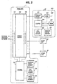
- the exchange lines are terminated through an interface 101 to one side of a switch matrix 102 of the main unit and the access units are terminated through an interface 103 to the other side of the switch matrix.
- a control unit 104 is connected to the interface units 101, 103 and switch 102 to establish a speech connection between therebetween after exchanging control signals with the access units using data stored in a registration memory 105, a call status memory 106 and a response status memory 107 in a manner as will be described in detail later.
- Each access unit comprises a coupling circuit 201 through which control signals from the main unit are supplied to the control unit 204 of the access unit and control signals from the access unit are supplied from control unit 204 through coupling circuit 201 to the main unit or a transceiver 202 where it is modulated onto a carrier and broadcast from antenna 203 to the cordless stations.
- Each access unit includes a timer 205 for setting a timeout period T, a call status memory 206 and a response status memory 207 which correspond respectively to the call and response status memories 106, 107 at the main unit.
- All memories of the system are of eight-bit configuration as shown in Figs. 3A and 3B.
- the eight-bit locations of each memory correspond respectively to cordless stations of a maximum number. Since it is assumed that the system has six cordless stations, bit zero's are set to the seventh and eighth positions of the registration memory 105 and response status memories 107, 207, and bit one's are set to the corresponding positions of the call status memories 106 and 206.
- the first to sixth bit positions of all memories are assigned respectively to cordless stations 31 to 36.
- Bits one's and zero's in the first to sixth positions of both call status memories 106, 206 respectively indicate busy and idle status of the corresponding cordless stations
- bits one's and zero's in the first to sixth positions of both response status memories 107, 207 respectively indicate the presence and absence of a response from the corresponding cordless stations.
- Data stored in registration memory 105 will be referred to as data A
- those stored in call and response status memories 106 and 107 will be referred to as data B and C, respectively.
- the data stored in call status memory 206 will be refereed to as data B since it is wholly updated with the contents of memory 106
- the data stored in response status memory 207 will be referred to as data c which forms part of data C.
- the control unit 104 at the main unit is a microprocessor-based controller which is programmed to execute instructions as shown in flowcharts of Figs. 4A and 4B, and the control unit 204 at each of the access units is also a microprocessor-based controller programmed to execute instructions as shown in flowcharts of Figs. 5A and 5B. Since the present invention is concerned only with the setting up of a connection when an incoming call is received from the network, all flowcharts illustrate those processes which are necessary for this purpose.
- step 401 determines whether an incoming call is received from the network. If the answer is affirmative, control branches to step 402 to select an idle access unit from each zone and send a first alert signal containing call status data B to the selected access units.
- copies of the first alert signals will be broadcast from the selected access units on the respectively assigned control channels, and acknowledgment (ACK) signals containing cordless station identifiers will be returned from the cordless stations which successfully received the alert signal using the same control channels.
- ACK acknowledgment
- Each of these access units returns a copy of the ACK response to the main unit and broadcasts a channel assignment signal indicating a speech channel to be used by the respective zone.
- channel assignment signal On receiving the channel assignment signal, each cordless station that returned the ACK switches its transceiver from the control channel to the assigned speech channel and returns a channel switching complete (CSC) signal to the associated access unit, where it is copied and sent to the main unit.
- CSC channel switching complete
- step 408 is executed to select an idle access unit from zones Z1 and Z3 and an another idle access unit from zones Z2 and Z4. Exit then is to step 409 to send to the selected units a second alert signal containing the identifier of the cordless station which is determined by step 407 as having failed to respond to the first alert signal.
- the access units selected by step 408 broadcast a copy of the received second alert signal and wait for the return of an ACK signal from a cordless station, which ACK signal contains the identifier of the station. If the access units receive an ACK, they will return a copy of the ACK signal to the main unit and wait for a channel assignment signal from the main unit.
- control proceeds to step 410 to receive the ACK signals from the selected access units and update the response status memory 107 with the identifiers of cordless stations which acknowledged the receipt of the second alert signal.
- step 411 to send a channel assignment signal to each ACK-returning access unit by containing in it the identifier of a speech channel which was previously selected by the access unit that forms a pair with the ACK-returning access unit to cover the same zone.
- step 412 to send a second ringing signal to that access unit which previously selected the speech channel to allow it to broadcast a copy of the second ringing signal over the speech channel.
- the second ringing signal contains the identifier of the station that failed to respond to the first alert signal. Therefore, this cordless station responds to it and operates its tone ringer.
- the access unit selected by step 408 deactivates its transceiver immediately following the transmission of the second ringing signal. All cordless stations are now alerted by ringing signals and one of the stations will go off hook and return an off-hook signal containing the identifier of the station to the associated access unit. A copy of the off-hook signal is sent from that access unit to the main unit.
- control proceeds to step 413 to receive the off-hook signal, and exits to step 414 to send a turn-on signal to that access unit, operate the switch matrix 102 to establish a connection, and send clear-down signals to other access units which are not associated with the cordless station that answered the call.
- the call status memory 106 of the associated access unit is then updated with the identifier contained in the off-hook signal (step 415), and the main unit now enters a talking mode.
- each cordless station operates in a battery saving mode in which the cordless station cyclically switches to a relatively short active period in which it alternately monitors control channels C1 and C2 and then switches to a relatively long idle period in which it cuts off its power supply, and this process is repeated at periodic intervals and continued during the standby mode.
- the cordless station disables the battery saving operation and enters a continued active state.
- the program execution at each of the access units begins with decision step 501 to determine whether either of first and second alert signals is received from the main unit. If the answer is affirmative, control branches out to step 502 to broadcast the received alert signal on the assigned control channel in order to elicit an ACK response from cordless stations, and updates the call status memory 206 with data contained in the received alert signal, so that the call status memory 206 is loaded with the contents of the call status memory 106 at the main unit. In this way, the alert signal is broadcast on control channel C1 in zones Z1 and Z3 and on control channel C2 in zones Z2 and Z4.
- step 503 to receive an ACK signal from a cordless station and send a copy of the ACK to the main unit, and then on to step 504 to update data c stored in the response status memory 207 with the identifier of the ACK-returning cordless station.
- step 506 allows each access unit to confirm that all cordless stations located in the same zone as the access unit have returned acknowledgment signals. If the answer is negative, control branches at step 506 to step 503 to repeat the process, and if affirmative, it branches to step 507 to check to see if at least one ACK signal is received within the period T. If it is, control proceeds to step 508, otherwise it returns to step 501, recognizing that there is no cordless station responding to the alert signal.
- control determines whether the alert signal received at step 501 is a first or second alert signal. If the signal received at step 501 is the first alert signal, control branches at step 508 to step 509 to select a speech channel and broadcast a speech channel assignment signal containing the identifier of the selected speech channel. On receiving the channel assignment signal, each cordless station switches its transceiver from the control channel to the selected speech channel and returns a channel switching complete (CSC) signal over the speech channel.
- CSC channel switching complete
- transceiver 202 is also switched from the control channel to the selected speech channel (step 510) to receive CSC signals from stations located in the same zone, and send copies of the CSC signals to the main unit (step 511).
- Control moves to step 512 to receive a first ringing signal from the main unit and broadcast its copy. Exit then is to step 513 to check to see if a second ringing signal is received from the main unit. If the answer is affirmative, control branches at step 513 to step 514 to broadcast a copy of the second ringing signal.
- Steps 513 and 514 are followed by decision step 515 to check to see if an off-hook signal is received from a cordless station. If the answer is affirmative, control branches at step 515 to 516 to transmit a copy of the off-hook signal to the main unit; otherwise it returns to step 501 to repeat the above process. control proceeds to step 517 to determine whether a turn-on or a clear-down signal is received from the main unit. If the turn-on signal is received, control moves to step 518 to broadcast its copy to allow the cordless station that answered the incoming call to turn on its speech circuit. If the clear-down signal is received, control branches at step 517 to step 519 to reset the access unit and enters a standby (idle) mode.
- step 501 If the signal received at step 501 is determined by step 508 to be a second alert signal, control branches out to step 520 to receive a channel assignment signal from the main unit and broadcast its copy in order to elicit an ACK response from a cordless station which has failed to respond to the first alert signal. Exit then is to step 521 to deactivate transceiver 202 and enters a standby state.
- call status memory 106 During the time just prior to the arrival of the incoming call, the contents of call status memory 106 are "0 0 0 0 0 1 0 0 " and cordless stations 31, 32, 34, 35 and 36 are operating in a battery saving mode as shown in Fig. 6.
- the arrival of the incoming call on exchange line 42 causes the main unit to select access units 21, 23, 25 and 27 and send a first alert signal to each of these units (steps 401, 402), whereupon it broadcasts a copy of the alert signal and updates the call status memory 206 as "0 0 0 0 0 1 0 0 " (steps 501, 502).
- the alert signals from access units 21, 23, 25 and 27 are respectively broadcast on control channels C1, C2, C1 and C2 (see Figs. 6 and 7).
- the first alert signal sent from access unit 21 (zone Z1) is received by both cordless stations 31 and 35, while in zones Z2 and Z4 the first alert signals from access units 23 and 27 are received by stations 32 and 34, respectively.
- cordless station 36 fails to respond to the first alert signal in zones Z2 and Z4.
- Cordless stations 31, 32, 34 and 35 return ACK signals, which are received by the associated access units, copied to the main unit and used to update response status memory 206 (steps 503, 504).
- the main unit receives the ACK signals from access units 21, 23 and 27 and updates its response status memory 106 so that data C reads "1 1 0 1 1 0 0 0" (step 403), and the response status memories 207 of access units 21, 23, 25 and 27 are updated with the identifier of the station returning the ACK.
- Access unit 21 "1 0 0 0 1 0 0 0"
- Access unit 23 "0 1 0 0 0 0 0 0"
- Access unit 25 "0 0 0 0 0 0 0 0”
- Access unit 27 "0 0 0 1 0 0 0 0" Since the complementary value of data B in each of these access units is "1 1 1 1 1 0 1 1", a negative decision results from step 505 in access units 21, 23, 25 and 27.
- Access units 21, 23 and 27 proceed to execute steps 505 through 507 and branches out step 508, while access unit 25 branches at step 507 to step 501 after executing the same steps.
- step 501 Since the signal received at step 501 is the first alert signal, access units 21, 23 and 27 branch at step 508 to step 509 to select speech channels S1, S2 and S3, respectively; and channel assignment signals are broadcast from these access units (step 509) and their transceivers are switched to the respective speech channels (step 510).
- speech channels S1 are established between access unit 21 and cordless stations 31 and 35
- speech channel S2 is established between access unit 23 and cordless station 32
- speech channel S3 is established between access unit 27 and cordless station 34.
- Cordless stations 31, 32, 34 and 35 return a channel switching complete (CSC) signal over the established speech channels, and copies of the CSC signals are transmitted to the main unit (steps 511, 404).
- First ringing signals are supplied from the main unit to access units 21, 23 and 27 (step 405) and transmitted to cordless stations 31, 32, 34 and 35 (step 512).
- the main unit Since there is one cordless station that has failed to respond to the first alert signal, the main unit makes a negative decision at step 406 and determines that it is the cordless station 36 failing to respond to the first alert signal (step 407), and executes step 408 to select an idle access unit from zones Z1 and Z3 and another unit from zones Z2 and Z4. If the main unit selects an access unit 22 from zones Z1 and Z3 and access unit 28 from zones Z2 and Z4, it sends a second alert signal containing the identifier of station 36 to each of access units 22 and 28 as well as data B stored in call status memory 106 (steps 409, 501, 502).
- Cordless station 36 now responds to the second alert signal by returning an ACK signal to access unit 28, whereas no ACK response is returned to access unit 22. Therefore, control at access unit 22 branches at step 503 to step 501 to enter a standby state, while access unit 28 returns a copy of the ACK response from station 36 to the main unit and updates its response status memory 207 (steps 504, 505).
- the main unit On receiving the ACK from access unit 28, the main unit updates its response status memory 106 (step 410) and sends a channel assignment signal to access unit 28, containing the identifier of speech channel S3 which was selected by access unit 27 for zone Z4. Following the transmission of the channel assignment signal, the main unit sends a second ringing signal to access unit 27 (step 412). On receiving the second ringing signal, access unit 27 broadcasts its copy to alert cordless station 36 (steps 513, 514). Meanwhile, access unit 28 is executing steps 506, 507, 508 and 520 to receive the channel assignment signal from the main unit and deactivate its transceiver 202 at step 521.
Landscapes
- Engineering & Computer Science (AREA)
- Computer Networks & Wireless Communication (AREA)
- Signal Processing (AREA)
- Mobile Radio Communication Systems (AREA)
- Sub-Exchange Stations And Push- Button Telephones (AREA)
Applications Claiming Priority (2)
| Application Number | Priority Date | Filing Date | Title |
|---|---|---|---|
| JP03241667A JP3083363B2 (ja) | 1991-09-20 | 1991-09-20 | コードレスボタン電話システムの着信方式 |
| JP241667/91 | 1991-09-20 |
Publications (3)
| Publication Number | Publication Date |
|---|---|
| EP0533509A2 true EP0533509A2 (de) | 1993-03-24 |
| EP0533509A3 EP0533509A3 (en) | 1993-11-10 |
| EP0533509B1 EP0533509B1 (de) | 1998-11-11 |
Family
ID=17077730
Family Applications (1)
| Application Number | Title | Priority Date | Filing Date |
|---|---|---|---|
| EP92308583A Expired - Lifetime EP0533509B1 (de) | 1991-09-20 | 1992-09-21 | Schnurlose Reihenanlage und entsprechendes Verfahren, um Anrufe an Stationen in durch Interferenz beeinflussten Zonen wiederholt zu versuchen |
Country Status (4)
| Country | Link |
|---|---|
| US (1) | US5305371A (de) |
| EP (1) | EP0533509B1 (de) |
| JP (1) | JP3083363B2 (de) |
| DE (1) | DE69227565T2 (de) |
Cited By (4)
| Publication number | Priority date | Publication date | Assignee | Title |
|---|---|---|---|---|
| WO1997005710A1 (en) * | 1995-07-28 | 1997-02-13 | International Mobile Satellite Organization | Spot beam location method and apparatus |
| WO1998023045A1 (en) * | 1996-11-20 | 1998-05-28 | Ico Services Ltd. | Method of communication establishing with a remote user |
| WO1998023046A3 (en) * | 1996-11-20 | 1998-10-08 | Int Mobile Satellite Org | High margin notification method and apparatus |
| WO2008128676A1 (de) * | 2007-04-23 | 2008-10-30 | T-Mobile International Ag | Verfahren zur sicherstellung der erreichbarkeit von mobilfunkendgeräten bei verwendung eines optimierten paging-mechanismus |
Families Citing this family (4)
| Publication number | Priority date | Publication date | Assignee | Title |
|---|---|---|---|---|
| US5546443A (en) * | 1992-10-26 | 1996-08-13 | Ericsson Ge Mobile Communications, Inc. | Communication management technique for a radiotelephone system including microcells |
| JPH07245775A (ja) * | 1994-03-07 | 1995-09-19 | Toshiba Commun Technol Kk | セルラ無線通信システムの移動局装置 |
| CN101001438B (zh) * | 2006-01-10 | 2010-12-08 | 华为技术有限公司 | 相邻基站间协商工作信道的方法 |
| CN100438701C (zh) * | 2006-04-17 | 2008-11-26 | 华为技术有限公司 | 语音组播广播业务中组播广播信道分配方法 |
Family Cites Families (8)
| Publication number | Priority date | Publication date | Assignee | Title |
|---|---|---|---|---|
| GB2165127B (en) * | 1984-09-26 | 1988-04-07 | Philips Electronic Associated | Multiple access communications system |
| US4829554A (en) * | 1985-01-31 | 1989-05-09 | Harris Corporation | Cellular mobile telephone system and method |
| EP0260991A3 (de) * | 1986-09-18 | 1990-01-17 | Sony Corporation | System und Verfahren für Funkverbindung |
| US5014295A (en) * | 1988-10-28 | 1991-05-07 | Sony Corporation | Multi-channel access cordless telephone system |
| GB8907317D0 (en) * | 1989-03-31 | 1989-05-17 | Plessey Telecomm | Communications systems |
| US5131010A (en) * | 1989-10-12 | 1992-07-14 | General Electric Company | Voice guard digital voter for multiple site PST RF trunking system |
| JP2806591B2 (ja) * | 1990-02-08 | 1998-09-30 | 日本電気株式会社 | 無線電話システムの着信方式 |
| US5218716A (en) * | 1990-11-05 | 1993-06-08 | Motorola, Inc. | Method for locating a communication unit within a multi mode communication system |
-
1991
- 1991-09-20 JP JP03241667A patent/JP3083363B2/ja not_active Expired - Fee Related
-
1992
- 1992-09-21 DE DE69227565T patent/DE69227565T2/de not_active Expired - Fee Related
- 1992-09-21 US US07/947,853 patent/US5305371A/en not_active Expired - Fee Related
- 1992-09-21 EP EP92308583A patent/EP0533509B1/de not_active Expired - Lifetime
Cited By (9)
| Publication number | Priority date | Publication date | Assignee | Title |
|---|---|---|---|---|
| WO1997005710A1 (en) * | 1995-07-28 | 1997-02-13 | International Mobile Satellite Organization | Spot beam location method and apparatus |
| US6522864B1 (en) | 1995-07-28 | 2003-02-18 | International Mobile Satellite Organization | Spot beam location method and apparatus |
| WO1998023045A1 (en) * | 1996-11-20 | 1998-05-28 | Ico Services Ltd. | Method of communication establishing with a remote user |
| WO1998023046A3 (en) * | 1996-11-20 | 1998-10-08 | Int Mobile Satellite Org | High margin notification method and apparatus |
| US6763240B1 (en) | 1996-11-20 | 2004-07-13 | Inmarsat Ltd. | High margin notification method and apparatus |
| US6954642B2 (en) | 1996-11-20 | 2005-10-11 | Inmarsat, Ltd. | High margin notification method and apparatus |
| WO2008128676A1 (de) * | 2007-04-23 | 2008-10-30 | T-Mobile International Ag | Verfahren zur sicherstellung der erreichbarkeit von mobilfunkendgeräten bei verwendung eines optimierten paging-mechanismus |
| CN101682851B (zh) * | 2007-04-23 | 2012-09-26 | T-移动国际股份公司 | 使用优化的寻呼机制保障移动无线终端机的可访问性的方法 |
| US8504078B2 (en) | 2007-04-23 | 2013-08-06 | T-Mobile International Ag | Method for ensuring the accessibility of mobile radio devices using an optimized paging mechanism |
Also Published As
| Publication number | Publication date |
|---|---|
| JP3083363B2 (ja) | 2000-09-04 |
| EP0533509B1 (de) | 1998-11-11 |
| DE69227565D1 (de) | 1998-12-17 |
| US5305371A (en) | 1994-04-19 |
| EP0533509A3 (en) | 1993-11-10 |
| DE69227565T2 (de) | 1999-08-12 |
| JPH0583192A (ja) | 1993-04-02 |
Similar Documents
| Publication | Publication Date | Title |
|---|---|---|
| EP0441370B1 (de) | Schnurloses Telefonsystem im Grossraum, geeignet zum Empfang ankommender Anrufe mit einer Gruppenadresse | |
| US5396496A (en) | Unused time slot detection and selection in a mobile radio communication system | |
| EP0910922B1 (de) | Notrufservice für mobiltelefon innerhalb des versorgungsgebiets eines mobilfunknetzes, für das es nicht registriert ist | |
| US5918181A (en) | Method and apparatus for tracking location of wireless terminals in a nanocellular digital cordless terminal network coupled to a local exchange | |
| EP0452872B1 (de) | Schnurlose Reihenanlage zur Abdeckung mehrerer Bedienungszonen mit exklusiver Zuteilung der Steuerkanäle | |
| AU636736B2 (en) | Cordless key telephone system capable of quickly answering incoming calls | |
| AU684221B2 (en) | Radiotelephone with multiple simultaneous telephone number identities | |
| EP0243900B1 (de) | Funktelefonsystem mit gemeinsamem Signalisierungskanal | |
| US5491741A (en) | Prioritizing a multiple access channel in a wireless telephone system | |
| EP0631417B1 (de) | Verfahren und Steuereinrichtung für ein Funktelefonsystem | |
| KR950013162B1 (ko) | 구역 교환 기능을 갖는 무선 키 전화 시스템 | |
| US5513248A (en) | Cordless telephone micro-cellular system | |
| WO1994019898A1 (en) | Method and apparatus in a communication system for completing an inbound call | |
| GB2292868A (en) | Cordless telephone systen | |
| EP0297914B1 (de) | Funkkommunikationssystem | |
| KR950013161B1 (ko) | 호출 설정 단계중에 신속 접속가능한 무선전화 장치 | |
| US5305371A (en) | Cordless key telephone system for repeating attempts to alert stations located in interference-affected zones | |
| EP0335742B1 (de) | Mobiles Kommunikationssystem und dessen Steuerungsverfahren | |
| AU2261295A (en) | Method for handling collision of calls | |
| JP2748716B2 (ja) | 移動通信システム | |
| JP2664830B2 (ja) | 通信中チャネル切替 | |
| JPH0738742B2 (ja) | 携帯電話報知制御方式 | |
| JPH09307934A (ja) | コードレス電話の親機 | |
| JPS62291234A (ja) | デ−タ通信装置 | |
| MXPA94005546A (en) | Method for operating a communication system having multiple base stations |
Legal Events
| Date | Code | Title | Description |
|---|---|---|---|
| PUAI | Public reference made under article 153(3) epc to a published international application that has entered the european phase |
Free format text: ORIGINAL CODE: 0009012 |
|
| AK | Designated contracting states |
Kind code of ref document: A2 Designated state(s): DE GB SE |
|
| PUAL | Search report despatched |
Free format text: ORIGINAL CODE: 0009013 |
|
| AK | Designated contracting states |
Kind code of ref document: A3 Designated state(s): DE GB SE |
|
| 17P | Request for examination filed |
Effective date: 19931027 |
|
| 17Q | First examination report despatched |
Effective date: 19960819 |
|
| GRAG | Despatch of communication of intention to grant |
Free format text: ORIGINAL CODE: EPIDOS AGRA |
|
| GRAG | Despatch of communication of intention to grant |
Free format text: ORIGINAL CODE: EPIDOS AGRA |
|
| GRAH | Despatch of communication of intention to grant a patent |
Free format text: ORIGINAL CODE: EPIDOS IGRA |
|
| GRAH | Despatch of communication of intention to grant a patent |
Free format text: ORIGINAL CODE: EPIDOS IGRA |
|
| GRAA | (expected) grant |
Free format text: ORIGINAL CODE: 0009210 |
|
| AK | Designated contracting states |
Kind code of ref document: B1 Designated state(s): DE GB SE |
|
| REF | Corresponds to: |
Ref document number: 69227565 Country of ref document: DE Date of ref document: 19981217 |
|
| PLBE | No opposition filed within time limit |
Free format text: ORIGINAL CODE: 0009261 |
|
| 26N | No opposition filed | ||
| PGFP | Annual fee paid to national office [announced via postgrant information from national office to epo] |
Ref country code: SE Payment date: 20010806 Year of fee payment: 10 |
|
| PGFP | Annual fee paid to national office [announced via postgrant information from national office to epo] |
Ref country code: GB Payment date: 20010919 Year of fee payment: 10 |
|
| PGFP | Annual fee paid to national office [announced via postgrant information from national office to epo] |
Ref country code: DE Payment date: 20011009 Year of fee payment: 10 |
|
| REG | Reference to a national code |
Ref country code: GB Ref legal event code: IF02 |
|
| PG25 | Lapsed in a contracting state [announced via postgrant information from national office to epo] |
Ref country code: GB Free format text: LAPSE BECAUSE OF NON-PAYMENT OF DUE FEES Effective date: 20020921 |
|
| PG25 | Lapsed in a contracting state [announced via postgrant information from national office to epo] |
Ref country code: SE Free format text: LAPSE BECAUSE OF NON-PAYMENT OF DUE FEES Effective date: 20020922 |
|
| PG25 | Lapsed in a contracting state [announced via postgrant information from national office to epo] |
Ref country code: DE Free format text: LAPSE BECAUSE OF NON-PAYMENT OF DUE FEES Effective date: 20030401 |
|
| EUG | Se: european patent has lapsed | ||
| GBPC | Gb: european patent ceased through non-payment of renewal fee |
Effective date: 20020921 |