EP0533537A1 - Ausrücklager für eine gezogene Kupplung, insbesondere für Kraftfahrzeuge - Google Patents
Ausrücklager für eine gezogene Kupplung, insbesondere für Kraftfahrzeuge Download PDFInfo
- Publication number
- EP0533537A1 EP0533537A1 EP92402477A EP92402477A EP0533537A1 EP 0533537 A1 EP0533537 A1 EP 0533537A1 EP 92402477 A EP92402477 A EP 92402477A EP 92402477 A EP92402477 A EP 92402477A EP 0533537 A1 EP0533537 A1 EP 0533537A1
- Authority
- EP
- European Patent Office
- Prior art keywords
- housing
- bearing
- clutch release
- release bearing
- ball bearing
- Prior art date
- Legal status (The legal status is an assumption and is not a legal conclusion. Google has not performed a legal analysis and makes no representation as to the accuracy of the status listed.)
- Granted
Links
- 230000008878 coupling Effects 0.000 claims abstract description 10
- 238000010168 coupling process Methods 0.000 claims abstract description 10
- 238000005859 coupling reaction Methods 0.000 claims abstract description 10
- 238000003032 molecular docking Methods 0.000 claims description 38
- 239000002184 metal Substances 0.000 claims description 6
- 229910052751 metal Inorganic materials 0.000 claims description 6
- 238000002788 crimping Methods 0.000 claims description 4
- 230000015572 biosynthetic process Effects 0.000 claims description 3
- 230000000149 penetrating effect Effects 0.000 claims description 2
- 229910001018 Cast iron Inorganic materials 0.000 description 2
- 238000006243 chemical reaction Methods 0.000 description 2
- 230000000694 effects Effects 0.000 description 2
- 230000035515 penetration Effects 0.000 description 2
- 239000007787 solid Substances 0.000 description 2
- 230000004308 accommodation Effects 0.000 description 1
- 239000003831 antifriction material Substances 0.000 description 1
- 238000010276 construction Methods 0.000 description 1
- 230000014759 maintenance of location Effects 0.000 description 1
- 230000002093 peripheral effect Effects 0.000 description 1
- 238000004804 winding Methods 0.000 description 1
Images


Classifications
-
- F—MECHANICAL ENGINEERING; LIGHTING; HEATING; WEAPONS; BLASTING
- F16—ENGINEERING ELEMENTS AND UNITS; GENERAL MEASURES FOR PRODUCING AND MAINTAINING EFFECTIVE FUNCTIONING OF MACHINES OR INSTALLATIONS; THERMAL INSULATION IN GENERAL
- F16D—COUPLINGS FOR TRANSMITTING ROTATION; CLUTCHES; BRAKES
- F16D23/00—Details of mechanically-actuated clutches not specific for one distinct type
- F16D23/12—Mechanical clutch-actuating mechanisms arranged outside the clutch as such
- F16D23/14—Clutch-actuating sleeves or bearings; Actuating members directly connected to clutch-actuating sleeves or bearings
- F16D23/143—Arrangements or details for the connection between the release bearing and the diaphragm
- F16D23/144—With a disengaging thrust-ring distinct from the release bearing, and secured to the diaphragm
- F16D23/145—Arrangements for the connection between the thrust-ring and the diaphragm
-
- F—MECHANICAL ENGINEERING; LIGHTING; HEATING; WEAPONS; BLASTING
- F16—ENGINEERING ELEMENTS AND UNITS; GENERAL MEASURES FOR PRODUCING AND MAINTAINING EFFECTIVE FUNCTIONING OF MACHINES OR INSTALLATIONS; THERMAL INSULATION IN GENERAL
- F16D—COUPLINGS FOR TRANSMITTING ROTATION; CLUTCHES; BRAKES
- F16D23/00—Details of mechanically-actuated clutches not specific for one distinct type
- F16D23/12—Mechanical clutch-actuating mechanisms arranged outside the clutch as such
- F16D23/14—Clutch-actuating sleeves or bearings; Actuating members directly connected to clutch-actuating sleeves or bearings
Definitions
- the present invention relates to clutch release bearings for a clutch of the pulled type, in particular for motor vehicles, as described in document US-A-4,405,041.
- the stop comprises an operating element subjected to the action of a declutching fork and a driving element, belonging to a housing, for action on the fingers of a diaphragm.
- the housing is attached to the end of said fingers using a docking piece and for this purpose centrally has a sleeve-shaped attack element passing through the diaphragm.
- the outer ring of a ball bearing is fixed to the housing, while the inner ring of this bearing is shaped to be connected in a connectable and disconnectable manner to a declutching fork by means of the movable operating element in translation. along a guide tube.
- This operating element comprises pivoting hooking fingers.
- a clutch release bearing assembly is created with a clutch release bearing provided with a housing belonging to a primary block comprising the clutch and an operating element belonging to a secondary block comprising the gearbox with its input shaft. .
- the stop being carried mainly by the clutch disengaging device, it follows that it is necessary, during the assembly of the clutch release clutch mounting, to effect a large relative movement of the secondary block by report to the primary block for threading the input shaft of the gearbox of speeds.
- the bearing and its housing can be damaged due to improper handling.
- the object of the present invention is to overcome these drawbacks in a simple and economical manner while continuing to benefit from a snap-on clutch release bearing assembly.
- an economical clutch release bearing is created thanks in particular to its ball bearing which can be of the standard type and to its simplified sleeve.
- the docking part is also simple by not having a ball bearing.
- the radial size of the bearing of the stop can be reduced, the operating element being less bulky radially than the picking fingers of the prior art.
- the mask housing the ball bearing and therefore protects it.
- the housing may by itself constitute the outer ring of the ball bearing.
- the radial size of the stop can be further reduced.
- the movement to be carried out is reduced in order to bring the primary block closer to the secondary block and to ensure assembly by simply snapping the stop with its docking part.
- the housing is less solid and can be mounted on a standard docking part.
- This box advantageously made of stamped sheet metal, can serve as a support for the clutch release fork during assembly of the clutch release bearing assembly.
- the inner ring of the bearing is simplified and it is also possible to create a declutching stop of the self-centering stop type, the securing means then comprising an elastic element bearing on the operating element to urge the inner ring of the bearing. ball in the direction of a shoulder carried by said operating element, a radial clearance existing between the inner ring of the ball bearing and the operating element.
- the operating element can internally carry a sliding ring facilitating its movement along a guide secured to the secondary block.
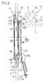
- FIG. 1 we see diagrammatically at 12 a docking assembly belonging to a primary block comprising a clutch of the pulled type, said docking assembly 12 comprising a docking part 16 suitably attached to the declutching device 11, which comprises the clutch, while a clutch release bearing is seen at 10 belonging to a secondary block comprising the gearbox.
- the stop 10 and the docking piece 16 are of annular shape.
- a clutch of the pulled type comprises a set of annular parts, namely, a friction disc, a reaction plate, a pressure plate (shown schematically in Figure 1), a hollow cover (shown schematically in Figure 1) and elastic means with axial action 11.
- these means 11 consist of a diaphragm 11 comprising a peripheral part forming a Belleville washer connecting to a central part fragmented into radial fingers 8 by slots.
- the fingers 8 belong to the clutch disengaging device.
- the elastic means may consist of a plurality of coil springs operated by declutching levers belonging to the clutch disengaging device.
- the diaphragm 11 bears on the cover to urge the pressure plate towards the reaction plate and tighten the friction linings, that usually comprises the friction disc, between said plates.
- a clutch release bearing assembly comprising for coupling the clutch release bearing 10 to the clutch release device 11, the docking part 16, which is suitably attached to said declutching device 11, and here means for securing in traction, which, established between the docking piece 16 and an attack piece 1 belonging to said clutch release bearing 10, are suitable for ensuring an axial connection between said docking and driving parts, going from said declutching device to the declutching stop.
- These traction securing means comprise, on the one hand, a radially elastically deformable coupling member 20, which is, at least partially engaged in an expansion recess 130 formed for it on the docking part 16, projecting radially vis-à-vis said part, in the free state, and, on the other hand, a drive surface 14 which is provided by means of an engagement recess 14 ′ formed on the docking part and with which said coupling member 20 cooperates axially bearing in the axial direction considered.
- the stop 10 comprises a hollow annular housing 36, a ball bearing 5, an operating element 9 suitable for being subjected to the action of a control member such as a clutch release fork on a piston of a control hydraulic.
- the housing 36 carries the driving element 1 and is integral with the rotating external ring of the ball bearing 5.
- the operating element 9 is adapted to slide along a guide tube 31 integral with the gearbox casing (shown diagrammatically at 37) and the secondary block.
- the bearing 5 is a bearing of the standard type.
- Securing means 6, 7, 80 intervene between the ball bearing 5 and the operating element 9 to axially subject the internal non-rotating ring of said bearing 5 to the tubular operating element 9 and ensure an axial connection between said bearing and said operating element going from the driving part 1 to the operating element 9.
- the housing 36 is made of stamped sheet metal being of annular shape, it comprises a skirt 4, of axial orientation, surrounding without play the outer ring of the ball bearing 5.
- the skirt 4 is extended at one of its ends by a fallen edge 3 directed radially towards the axis of the assembly, said dropped edge being extended towards the axis of the assembly by a connection portion 2 of tortuous and inclined shape, which is connected to a generally cylindrical portion in the form of a socket 1 constituting the attack element according to the invention.
- This attack element penetrates inside the docking part, more particularly inside the sleeve 18 of the latter described below.
- the engagement recess 14 ′ for the coupling member 20 here in the form of a rod.
- This recess consists of a groove, one of the flanks 14 of which constitutes the drive surface, that is to say the one furthest from the bearing 5 and closest to the free end of the bush 1, chamfered to facilitate the penetration of the attack element 1 inside the rod 20 as described below.
- the other end of the skirt 4, initially straight (FIG. 1), is folded radially inwards to trap the outer ring of the bearing 5, which makes it possible to reduce the thickness of the housing 36.
- This folded end allows the formation of a support for the clutch release fork (not visible) during the snap-fit assembly of the clutch release bearing assembly.
- this outer ring is fixed to the housing 36 by crimping, said ring being trapped by the fallen edge 3, the skirt 4 and the other end of the folded skirt.
- the operating element has the overall shape of a sleeve and has transversely at one of its ends at least two tabs 21 for mounting hardened pins 23 serving to support the fingers of a clutch release fork in a known manner in itself.
- This fork can be coupled to the legs 21, for example by springs, to allow the assembly of the clutch release bearing assembly.
- the sleeve 9 here made of cast iron, carries a sliding ring 33 made of anti-friction material, for example plastic, for good sliding along the guide 31.
- This ring 33 is secured to the sleeve 9 by force engagement, said ring having a rib 34 engaged in a generally trapezoidal groove 35, which internally has the internal bore of the sleeve 9.
- this sleeve 9 has two shoulders 6, 80 offset axially with respect to each other for mounting the internal ring of the bearing 5. More specifically, the sleeve 9 has a change in diameter to form a shoulder 80.
- This change in diameter affects the sleeve 9 at its free end opposite to that having the lugs 21.
- This free end has a groove for mounting a circlip 6.
- This circlip 6 is mounted in favor of the connection portion 2, releasing a volume for mounting said circlip for the benefit of the compactness of the stop.
- the bush 1 extends radially below the internal ring of the bearing 5.
- the housing 36 thanks to its connection portion 2, masks the bearing 5 and therefore protects it.
- the axial offset between the skirt 4 and the sleeve 1 is such that no interference is not to be feared between the sleeve and the free end of the sleeve 9.
- the inner ring of the bearing 5 is mounted with radial clearance relative to the sleeve 9 and can move radially with the housing 36 relative to the sleeve 9 under the control of the Belleville washer 7.
- the housing 36 can be shaped to form itself the outer ring of the ball bearing, which reduces the radial size of the stop.
- the housing has no fallen edge, its connection portion 2 allowing the housing of the circlip 6 as before.
- the axial offset between the outer ring and the bush 1 is achieved by extending said ring axially, the portion 2 being transverse.
- the driving element 1 of this stop 10 is suitable for being snapped onto the docking assembly 12.
- This docking assembly 12 comprises a docking part 16 with a flange 17 of curved shape, for pressing on the end of the fingers 8 of the diaphragm 11, on the face of these turned opposite to the bearing 5.
- This flange 17 is connected to a socket 18.
- the diaphragm 11 With regard to the diaphragm 11, it will be noted that its central part is formed by radial fingers 8 separated by slots (FIG. 3) and that axially the latter has a central opening 15 suitable for being traversed by the sleeve 18.
- the piece of docking 16 is here in stamped sheet metal.
- the flange 17 of the docking part 16 has, from place to place at its outer periphery, fingers 25, which, axially directed in the same direction as the sleeve 18 of the docking part, pass through the diaphragm 11, each favoring a slot separating the fingers from the latter and which each carries circumferentially cantilevered in line with the support flange 17, and generally parallel thereto, retaining fingers 40 suitable for ensuring, in cooperation with this collar 17, the axial retention of the assembly on the diaphragm.
- the end of the fingers 25 may have a groove for mounting a Belleville washer, the internal end of which comes to bear on the fingers 8 of the diaphragm 11.
- the docking piece 16 is then attached by pinching on the fingers 8.
- Other devices can be provided for securing the docking piece to the fingers of the diaphragm.
- the radially elastically deformable coupling rod 20 extends in a plane substantially perpendicular to the axis of the assembly and is made of round wire. It is open and has two strands 121A, 121B, which each pass through the socket 18 in favor of two recesses 22A, 22B distinct from the latter, by reason of a recess by strands, and extend outside of the socket 18.
- the part of the sleeve 18, which has the recesses 22A, 22B for the passage of the strands 121A, 121B, is deformed at least partially radially in the direction opposite to the axis of the assembly, along a concave bulge 132 towards the axis from the whole.
- the sleeve 18 comprises, in addition to a frustoconical section 124, internally offering a frustoconical bearing, two cylindrical parts 130, 131 extending on either side of said section 124.
- Part 130 constitutes the expansion recess according to the invention. It has a larger diameter and is connected by an elbow to the collar 17, while the part 131 forms the free end of the sleeve 18, being chamfered and of smaller diameter.
- the domed local 132 partially affects the deck 32, as well as the entire portion 131 in the axial alignment of the deck 32.
- the rod 20 comprises at least one additional tab 23, which, extending radially, is itself engaged with a recess 24 of the sleeve 18 which is wider axially.
- two additional radial lugs 23, in the form of a half-wave deformation, and two recesses 24 are provided, each generally at 120 ° relative to the recesses 22A, 22B; said tabs 23 being in contact only with one of the lateral or circumferential edges of the recesses 24, in order to promote the expansion of the rod 20 when the stop 10 is snapped in.
- the two strands 121A, 121B each have a deformation 122A, 122B lengthening their length, elastically.
- loops 122A, 122B consist of loops 122A, 122B. Said loops each form a tension spring type loop, and extend after mounting, radially above the stop.
- the strands 121A, 121B have, below the loops 122A, 122B, two elbows which result that, axially offset from the rod 20, their ends extend jointly in a parallel plane said ring between the stop 10 and the diaphragm 11.
- the end of the strand 121B obliquely forms a hook 30 suitable for its elastic hooking on the current part of the strand 121A.
- Each of the strands 121A, 121B after passing through the recesses 22A, 22B, has a portion of axial orientation 125 in contact, before mounting of the stop, of the external surface of the sleeve 18, and more precisely of the part 131, said portion extending by a first radial portion 126, then by a second inclined radial portion 127 in the plane of Figure 4 and comprising the loop according to the invention.
- the portions 126 are closer together than the portions 127 and allow the diaphragm 11 to tilt.
- An S-shaped fold 128 connects the two said portions 126, 127 which are mutually parallel from one strand 121A to the other strand 121B.
- the portion 127 comprises two radial parts offset axially and parallel to each other, said parts being connected by the inclined part 129 of a loop 122A, 122B.
- said inclined portion 129 generally forms a turn of a helical spring and said loops constitute a spring of the spring type "clothespin". The loops therefore constitute a winding.
- the folds 128 allow the accommodation of the loops.
- the diaphragm has a clearance 200 opposite the recesses 22A, 22B to facilitate assembly of the rod 20.
- the two affected fingers 8 of the diaphragm are cut off at their internal periphery.
- the clearance 200 then allows the passage of the portion 125, the expansion of the rod 20, favored by the loops according to the invention, being carried out satisfactorily by pressing on said bottom, the convex 132 allowing a prepositioning of the rod.
- the gearbox is brought closer to the engine block with its diaphragm 11 equipped with the docking assembly 12.
- the rod 20 is advantageously in free configuration.
- the chamfered free end of the driving element 1 is allowed to penetrate inside the ring 20 and the bush 18 for effortless mounting by snap-fastening of the stop 10 on the rod.
- the rod 20 is wedged between the drive surface 14 of the attack piece and the frustoconical section 124 of the docking piece. The declutching forces thus pass through the rod 20.
- the present invention is not limited to the embodiments described.
- the sleeve 9 can be provided with a transverse flange and be subjected, for example, to the action of at least one piston movable relative to a cylinder with definition of a control chamber between said pieces.
- the cylinder is fixed and the piston in this case constitute the control means for, like the declutching fork, maneuver the sleeve 9 and move it along the guide tube 31 in order to effect by traction an operation of the clutch.
- any other form of shoulder can be provided, for example a shoulder coming from the sleeve 9 and obtained by crimping.
- the shoulder 80 may consist of a circlip like the other shoulder 6, the change in diameter then not being compulsory.
- connection portion 2 of the housing 36 makes it possible to create an axial offset between the bearing 5 and the driving element 1 to release a volume in order to carry out the mounting and housing of the shoulder 6 such as the circlips. 6.
- the sleeve 9 instead of being made of cast iron, can be of pressed sheet metal.
- the axial connection sleeve 9 - bearing 5 can be of the non-self-centering type. In this case, the bearing is mounted without play on the sleeve while being immobilized axially between the shoulders 6,80.
- the stop is mounted blind, by simple snap-fastening, on a simplified docking part, thanks to its engagement recess, and is itself economical.
- its housing made of pressed sheet metal and not very solid, is integral with the outer ring of a standard ball bearing, the inner ring of which is axially subject to a shouldered sleeve, suitable for carrying a sliding ring.
- the engagement groove 14 ′ is easily achievable in all cases by stamping.
- the groove 14 ′ can be produced by turning.
- connection portion 2 of the housing 36 can interpose between it and the free end of the socket 18 an elastic washer with axial action 83, such as a Belleville or wavy washer.
- an elastic washer with axial action 83 such as a Belleville or wavy washer.
- the internal periphery of the connection portion is shaped to form a shoulder for the washer 83.
- the rod 20 is constantly wedged between the drive surface 14 and the frustoconical surface 124.
- the docking part may be massive and internally carry an elastically deformable radially open ring, said ring being engaged in an expansion groove made in the internal bore of the docking part and being suitable for penetrating into the engagement groove 14 ′ of the attack element 1.
- the operating element can be the piston of a hydraulic control.
- the dorsal end of this operating element comprises, on the one hand, a radial dorsal rim directed inwards and, on the other hand, is slidably mounted on a cylinder whose front end has a front rim directed inward.
- a control chamber is thus defined between said back and front flanges with seals mounted in said flanges and a supply installed in the operating element for supplying the control chamber.
- a removable shim can be installed between the dorsal end of the element and the gearbox casing to keep the piston in the retracted position and facilitate assembly of the docking part with the stop.
- the operating element generally has a tubular shape with a flange extending radially outward or inward.
Landscapes
- Engineering & Computer Science (AREA)
- General Engineering & Computer Science (AREA)
- Mechanical Engineering (AREA)
- Mechanical Operated Clutches (AREA)
Applications Claiming Priority (2)
| Application Number | Priority Date | Filing Date | Title |
|---|---|---|---|
| FR9111444 | 1991-09-17 | ||
| FR9111444A FR2681392B1 (fr) | 1991-09-17 | 1991-09-17 | Butee de debrayage pour embrayage du type tire, notamment pour vehicules automobiles. |
Publications (2)
| Publication Number | Publication Date |
|---|---|
| EP0533537A1 true EP0533537A1 (de) | 1993-03-24 |
| EP0533537B1 EP0533537B1 (de) | 1994-11-02 |
Family
ID=9417018
Family Applications (1)
| Application Number | Title | Priority Date | Filing Date |
|---|---|---|---|
| EP92402477A Expired - Lifetime EP0533537B1 (de) | 1991-09-17 | 1992-09-10 | Ausrücklager für eine gezogene Kupplung, insbesondere für Kraftfahrzeuge |
Country Status (4)
| Country | Link |
|---|---|
| US (1) | US5284233A (de) |
| EP (1) | EP0533537B1 (de) |
| DE (1) | DE69200623T2 (de) |
| FR (1) | FR2681392B1 (de) |
Cited By (2)
| Publication number | Priority date | Publication date | Assignee | Title |
|---|---|---|---|---|
| EP2017491A1 (de) * | 2007-07-20 | 2009-01-21 | SNR Roulements | Herstellungsverfahren und mechanisch verstärkte Autozentrierscheibe |
| EP2132454B1 (de) * | 2007-03-07 | 2013-08-21 | Schaeffler Technologies AG & Co. KG | Verfahren zur herstellung einer kupplungsausrücklagereinrichtung mit einer anbindungsstruktur zur anbindung eines kupplungsausrücklagers an eine stellstange |
Families Citing this family (3)
| Publication number | Priority date | Publication date | Assignee | Title |
|---|---|---|---|---|
| US5653323A (en) * | 1996-02-21 | 1997-08-05 | L & S Bearing Co. | Clutch release bearing assembly |
| DE10138722C5 (de) * | 2000-08-17 | 2017-05-24 | Schaeffler Technologies AG & Co. KG | Antriebsstrang |
| US8191699B2 (en) * | 2008-01-25 | 2012-06-05 | Schaeffler Technologies AG & Co. KG | Friction clutch |
Citations (3)
| Publication number | Priority date | Publication date | Assignee | Title |
|---|---|---|---|---|
| FR1467848A (fr) * | 1965-12-20 | 1967-02-03 | Ferodo Sa | Butée de débrayage, et embrayage la comportant |
| FR2304826A1 (fr) * | 1975-03-19 | 1976-10-15 | Ferodo Sa | Mecanisme de commande en rotation notamment pour vehicule automobile, et embrayage et butee de debrayage propres a la realisation d'un tel mecanisme |
| FR2350505A1 (fr) * | 1976-05-06 | 1977-12-02 | Skf Kugellagerfabriken Gmbh | Butee de debrayage |
Family Cites Families (4)
| Publication number | Priority date | Publication date | Assignee | Title |
|---|---|---|---|---|
| DE2639766C2 (de) * | 1976-09-03 | 1986-01-09 | LuK Lamellen und Kupplungsbau GmbH, 7580 Bühl | Reibungskupplungseinheit |
| EP0044691B1 (de) * | 1980-07-22 | 1984-09-19 | Automotive Products Public Limited Company | Zieheinrichtung zum Lösen einer Kupplung |
| FR2653195B1 (fr) * | 1989-10-13 | 1991-12-06 | Valeo | Ensemble d'accostage pour butee de debrayage, notamment pour vehicule automobile. |
| FR2683284B1 (fr) * | 1991-10-31 | 1997-08-08 | Valeo | Butee de debrayage hydraulique, pour montage de butee de debrayage et procede d'assemblage d'un tel montage de butee de debrayage. |
-
1991
- 1991-09-17 FR FR9111444A patent/FR2681392B1/fr not_active Expired - Fee Related
-
1992
- 1992-09-10 DE DE69200623T patent/DE69200623T2/de not_active Expired - Fee Related
- 1992-09-10 EP EP92402477A patent/EP0533537B1/de not_active Expired - Lifetime
- 1992-09-14 US US07/944,659 patent/US5284233A/en not_active Expired - Lifetime
Patent Citations (3)
| Publication number | Priority date | Publication date | Assignee | Title |
|---|---|---|---|---|
| FR1467848A (fr) * | 1965-12-20 | 1967-02-03 | Ferodo Sa | Butée de débrayage, et embrayage la comportant |
| FR2304826A1 (fr) * | 1975-03-19 | 1976-10-15 | Ferodo Sa | Mecanisme de commande en rotation notamment pour vehicule automobile, et embrayage et butee de debrayage propres a la realisation d'un tel mecanisme |
| FR2350505A1 (fr) * | 1976-05-06 | 1977-12-02 | Skf Kugellagerfabriken Gmbh | Butee de debrayage |
Cited By (3)
| Publication number | Priority date | Publication date | Assignee | Title |
|---|---|---|---|---|
| EP2132454B1 (de) * | 2007-03-07 | 2013-08-21 | Schaeffler Technologies AG & Co. KG | Verfahren zur herstellung einer kupplungsausrücklagereinrichtung mit einer anbindungsstruktur zur anbindung eines kupplungsausrücklagers an eine stellstange |
| EP2017491A1 (de) * | 2007-07-20 | 2009-01-21 | SNR Roulements | Herstellungsverfahren und mechanisch verstärkte Autozentrierscheibe |
| FR2919033A1 (fr) * | 2007-07-20 | 2009-01-23 | Snr Roulements Sa | Procede de fabrication et rondelle d'autocentrage renforcee mecaniquement |
Also Published As
| Publication number | Publication date |
|---|---|
| DE69200623T2 (de) | 1995-03-23 |
| FR2681392B1 (fr) | 1993-12-10 |
| EP0533537B1 (de) | 1994-11-02 |
| FR2681392A1 (fr) | 1993-03-19 |
| US5284233A (en) | 1994-02-08 |
| DE69200623D1 (de) | 1994-12-08 |
Similar Documents
| Publication | Publication Date | Title |
|---|---|---|
| FR2557234A1 (fr) | Montage de butee de debrayage, et butee de debrayage propre a un tel montage | |
| FR2508125A1 (fr) | Butee de debrayage, notamment pour vehicule automobile, et son procede de montage | |
| EP0243229B1 (de) | Zusammenbau eines Kupplungsausrücklagers, insbesondere für ein Kraftfahrzeug | |
| EP0443935B1 (de) | Vorrichtung zur Betätigung einer Kupplung, insbesondere für ein Kraftfahrzeug | |
| FR2597561A1 (fr) | Mecanisme a roulement de debrayage | |
| EP0220982B1 (de) | Aufstellung eines Kupplungsausrückers, insbesondere für ein Kraftfahrzeug | |
| EP0533537B1 (de) | Ausrücklager für eine gezogene Kupplung, insbesondere für Kraftfahrzeuge | |
| EP0892188B1 (de) | Kupplungsausrücklager mit angesetzter Anschlagsdruckplatte | |
| FR2607885A1 (fr) | Butee de debrayage a rondelle elastique bistable, notamment pour vehicule automobile | |
| WO2000057076A1 (fr) | Dispositif de montage d'un diaphragme sur un couvercle d'embrayage | |
| FR2683284A1 (fr) | Butee de debrayage hydraulique, pour montage de butee de debrayage et procede d'assemblage d'un tel montage de butee de debrayage. | |
| FR2588050A1 (fr) | Embrayage du type a ressort a diaphragme | |
| EP0360650B1 (de) | Kupplungsausrücklager, insbesondere für Kraftfahrzeuge | |
| FR2618504A1 (fr) | Butee de debrayage, notamment pour vehicule automobile, et montage de butee de debrayage correspondant | |
| EP3885592A1 (de) | Blindmontageanordnung eines bremsseils an einem betätigungshebel einer kraftfahrzeug-trommelbremse | |
| FR2653194A1 (fr) | Ensemble d'accostage pour butee de debrayage, notamment pour vehicule automobile, et piece d'accostage d'un tel ensemble. | |
| FR2658878A1 (fr) | Dispositif de connexion rapide entre deux portions d'une timonerie, notamment pour vehicule automobile. | |
| FR2588051A1 (fr) | Montage de butee de debrayage, notamment pour vehicule automobile | |
| FR3096422A1 (fr) | Frein à tambour a couple residuel reduit | |
| FR2654785A1 (fr) | Butee de debrayage, notamment pour vehicule automobile. | |
| FR3050783B1 (fr) | Ensemble pour un dispositif d'embrayage, notamment pour vehicule automobile | |
| FR2695693A1 (fr) | Dispositif d'immobilisation d'une gaine de câble sur un support quelconque. | |
| FR2701079A1 (fr) | Dispositif de débrayage à encliqueter sur un embrayage de type tiré. | |
| FR3067774B1 (fr) | Dispositif de synchronisation d’une boite de vitesses | |
| FR2742200A1 (fr) | Montage de butee de debrayage, notamment pour vehicule automobile |
Legal Events
| Date | Code | Title | Description |
|---|---|---|---|
| PUAI | Public reference made under article 153(3) epc to a published international application that has entered the european phase |
Free format text: ORIGINAL CODE: 0009012 |
|
| AK | Designated contracting states |
Kind code of ref document: A1 Designated state(s): DE GB IT |
|
| 17P | Request for examination filed |
Effective date: 19930616 |
|
| 17Q | First examination report despatched |
Effective date: 19930830 |
|
| GRAA | (expected) grant |
Free format text: ORIGINAL CODE: 0009210 |
|
| AK | Designated contracting states |
Kind code of ref document: B1 Designated state(s): DE GB IT |
|
| REF | Corresponds to: |
Ref document number: 69200623 Country of ref document: DE Date of ref document: 19941208 |
|
| GBT | Gb: translation of ep patent filed (gb section 77(6)(a)/1977) |
Effective date: 19941111 |
|
| ITF | It: translation for a ep patent filed | ||
| PLBE | No opposition filed within time limit |
Free format text: ORIGINAL CODE: 0009261 |
|
| STAA | Information on the status of an ep patent application or granted ep patent |
Free format text: STATUS: NO OPPOSITION FILED WITHIN TIME LIMIT |
|
| 26N | No opposition filed | ||
| PGFP | Annual fee paid to national office [announced via postgrant information from national office to epo] |
Ref country code: GB Payment date: 19960828 Year of fee payment: 5 |
|
| PG25 | Lapsed in a contracting state [announced via postgrant information from national office to epo] |
Ref country code: GB Free format text: LAPSE BECAUSE OF NON-PAYMENT OF DUE FEES Effective date: 19970910 |
|
| GBPC | Gb: european patent ceased through non-payment of renewal fee |
Effective date: 19970910 |
|
| PGFP | Annual fee paid to national office [announced via postgrant information from national office to epo] |
Ref country code: DE Payment date: 20070910 Year of fee payment: 16 |
|
| PGFP | Annual fee paid to national office [announced via postgrant information from national office to epo] |
Ref country code: IT Payment date: 20070915 Year of fee payment: 16 |
|
| PG25 | Lapsed in a contracting state [announced via postgrant information from national office to epo] |
Ref country code: IT Free format text: LAPSE BECAUSE OF NON-PAYMENT OF DUE FEES Effective date: 20080910 Ref country code: DE Free format text: LAPSE BECAUSE OF NON-PAYMENT OF DUE FEES Effective date: 20090401 |