EP0533651A2 - Dispositif et procédé de mesure pour la détermination des propriétés d'un échantillon - Google Patents
Dispositif et procédé de mesure pour la détermination des propriétés d'un échantillon Download PDFInfo
- Publication number
- EP0533651A2 EP0533651A2 EP92890196A EP92890196A EP0533651A2 EP 0533651 A2 EP0533651 A2 EP 0533651A2 EP 92890196 A EP92890196 A EP 92890196A EP 92890196 A EP92890196 A EP 92890196A EP 0533651 A2 EP0533651 A2 EP 0533651A2
- Authority
- EP
- European Patent Office
- Prior art keywords
- sample
- measuring
- radiation
- lighting
- sources
- Prior art date
- Legal status (The legal status is an assumption and is not a legal conclusion. Google has not performed a legal analysis and makes no representation as to the accuracy of the status listed.)
- Granted
Links
Images
Classifications
-
- G—PHYSICS
- G01—MEASURING; TESTING
- G01N—INVESTIGATING OR ANALYSING MATERIALS BY DETERMINING THEIR CHEMICAL OR PHYSICAL PROPERTIES
- G01N21/00—Investigating or analysing materials by the use of optical means, i.e. using sub-millimetre waves, infrared, visible or ultraviolet light
- G01N21/17—Systems in which incident light is modified in accordance with the properties of the material investigated
- G01N21/25—Colour; Spectral properties, i.e. comparison of effect of material on the light at two or more different wavelengths or wavelength bands
- G01N21/27—Colour; Spectral properties, i.e. comparison of effect of material on the light at two or more different wavelengths or wavelength bands using photo-electric detection ; circuits for computing concentration
- G01N21/274—Calibration, base line adjustment, drift correction
-
- G—PHYSICS
- G01—MEASURING; TESTING
- G01N—INVESTIGATING OR ANALYSING MATERIALS BY DETERMINING THEIR CHEMICAL OR PHYSICAL PROPERTIES
- G01N2201/00—Features of devices classified in G01N21/00
- G01N2201/06—Illumination; Optics
- G01N2201/061—Sources
Definitions
- the invention relates to a measuring device with an electromagnetic radiation, in particular visible light, emitting lighting arrangement, a sample area illuminated by the latter and a measuring arrangement which detects the radiation influenced by a sample in the sample area and converts it into a measurement signal, and with a calibration device for the controlled Reduction of the intensity of the radiation reaching the sample area during a linearity check of the device.
- an electromagnetic radiation in particular visible light, emitting lighting arrangement
- a sample area illuminated by the latter and a measuring arrangement which detects the radiation influenced by a sample in the sample area and converts it into a measurement signal
- a calibration device for the controlled Reduction of the intensity of the radiation reaching the sample area during a linearity check of the device.
- the invention also relates to a measuring method for determining properties of a sample by detecting the influence of electromagnetic radiation, in particular visible light, by the sample, a controlled reduction in the intensity of the radiation reaching the sample being carried out for the purpose of checking the linearity.
- Devices and methods of the type mentioned are known in a wide variety of contexts and configurations and, for example, enable measurements on and statements about the exhaust gas from internal combustion engines in the so-called opacimetric measuring method in exhaust gas measuring technology.
- Such measuring devices or methods based on the opacimeter principle evaluate the attenuation of a radiation current generated by a lighting arrangement and detected by a suitable photo element or the like (in particular luminous flux in the visible spectral range) by means of evaluation electronics using a sample gas present in a sample gas tube.
- the weakening or extinction of the light is caused by various physical effects, in particular absorption and scattering.
- a halogen lamp with radiation of incoherent light over a large part of the visible is preferably used as the illumination source Spectral range used.
- other lighting sources in particular light-emitting diodes with intensity maxima in the area of green light, are also used.
- the measured signal level detected in the photo element of the measuring arrangement is proportional to the incident luminous flux (corresponding to the lighting intensity), which means that the measuring device works in principle linearly.
- measuring devices of the type mentioned therefore include, in addition to the possibility of calibrating the zero point when the lighting arrangement is switched off and the maximum value with a clean sample, also a calibration device to simplify the linearity of the measuring device in individual measuring ranges, usually a single measuring point in the middle of the measuring range Means to check.
- the state of the art for carrying out this simple linearity check is a filter disk with a defined damping that can be pushed into the illumination path, or a mechanical shutter with a defined opening that can be pushed in.
- This filter disk or diaphragm can be inserted manually or for automated operation of the measuring device with the aid of an actuator, such as a lifting magnet or an electric motor. In both cases, a part of the flowing lighting current that is defined as precisely as possible is shadowed and the measurement result determined by the measuring device is compared with the defined target value.
- Filter disks with defined attenuation of the lighting which do not have the disadvantage of being directly dependent on the geometric arrangement, and which are therefore used for calibrations under laboratory conditions, can only be used for automated linearity checking with considerable effort.
- a falsification of the degree of damping by any contamination under difficult environmental conditions, as is particularly true for workshop measuring devices, must be prevented.
- the object of the present invention is to improve a measuring device or a measuring method of the type mentioned at the outset such that the disadvantages of the known devices and methods mentioned do not occur and that, in particular, simple and precise means can be used to carry out precise and meaningful linearity checks.
- the lighting arrangement has a plurality of independent lighting sources which can be operated individually or jointly by the calibration device via separate feed lines and switching elements for checking the linearity of the device.
- the corresponding embodiment of the measuring method according to the invention is characterized in that the intensity contributions of several radiation sources to be operated selectively are determined, added and compared to the total intensity when all radiation sources are in operation.
- the invention thus enables a linearity check by means of a plurality of selectively switchable light or lighting sources which are operated one after the other individually or in any groups, after which the associated photo streams can be detected.
- the voltage source supplying the lighting arrangement can preferably - as in the case of conventional arrangements with only one light source - be designed to be regulated in order to keep the temporal drift of the measured values low and also to avoid a change in the supply voltage due to the different loads during the linearity check.
- the lighting arrangement has two essentially identical lighting sources arranged side by side or one behind the other, which enables a simple configuration of the device with only a few additional individual parts and is sufficient for most measuring purposes is.
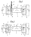
- Fig. 1 shows an opacimetric measuring device according to the prior art
- Fig. 2 shows a corresponding measuring device according to the present invention.
- the known measuring device essentially consists of a lighting arrangement 1, a sample area 2 - here in the form of a sample gas tube 3 through which sample gas flows through the arrows 4 - and a measuring arrangement 5 and a calibration device 6.
- the lighting arrangement 1 has a single lighting source 8 in a light head 7, formed for example by a halogen lamp or the like, which is connected via a feed line 9 to a switching element 10 and a voltage supply 11. On the exit side, the light head 7 is provided with a diffusing screen 12 for uniformizing the luminous flux.
- the measuring arrangement 5 is constructed similarly to the light head.
- filter disks 12 ' are arranged behind which there is a photo element 13 which is connected via lines 14 to an evaluation device 15, for example in the simplest form an ammeter.
- the calibration device 6 is arranged in the form of a filter disk 18 which can be displaced in a guide 16 along the double arrow 17 and which has a defined damping, with which - when the filter disk 18 is pushed in front of the lens 12 - a precisely defined part of the luminous flux otherwise flowing through the sample gas tube 3 is shadowed and the overall result determined by the measuring device can be compared with the defined target value.
- the sample area 2 and the measuring arrangement 5 correspond practically unchanged to the measuring device according to FIG. 1 — the same parts are provided with the same reference numbers here (and also in the case of the light head 7) the description of the basic function corresponds essentially to the device according to FIG. 1, so that in order to avoid repetition, reference is made here only to the above statements.
- the calibration device 6 is essentially only with regard to the calibration device 6, or the correspondingly modified lighting arrangement 1, which here now has two independent lighting sources 8 ', which have separate feed lines 9' and switching elements 10 'from the calibration device 6 can be operated selectively or individually for linearity checking of the device.
- the intensity contributions of the two illumination sources 8 ' can thus be individually determined by means of the measuring arrangement 5, added in the evaluation device 15 and the total intensity when the two radiation sources 8 are in operation are compared. This enables simple and accurate linearity checks, and, if necessary, the operation of the entire device with only one of the two lighting sources 8 '.
Landscapes
- Physics & Mathematics (AREA)
- Analytical Chemistry (AREA)
- General Physics & Mathematics (AREA)
- Theoretical Computer Science (AREA)
- Spectroscopy & Molecular Physics (AREA)
- Health & Medical Sciences (AREA)
- Life Sciences & Earth Sciences (AREA)
- Mathematical Physics (AREA)
- Biochemistry (AREA)
- Chemical & Material Sciences (AREA)
- General Health & Medical Sciences (AREA)
- Engineering & Computer Science (AREA)
- Immunology (AREA)
- Pathology (AREA)
- Investigating Or Analysing Materials By Optical Means (AREA)
- Analysing Materials By The Use Of Radiation (AREA)
Applications Claiming Priority (2)
| Application Number | Priority Date | Filing Date | Title |
|---|---|---|---|
| AT1898/91 | 1991-09-20 | ||
| AT0189891A AT399053B (de) | 1991-09-20 | 1991-09-20 | Messeinrichtung zur bestimmung von eigenschaften einer probe |
Publications (3)
| Publication Number | Publication Date |
|---|---|
| EP0533651A2 true EP0533651A2 (fr) | 1993-03-24 |
| EP0533651A3 EP0533651A3 (fr) | 1993-05-26 |
| EP0533651B1 EP0533651B1 (fr) | 1996-04-03 |
Family
ID=3523409
Family Applications (1)
| Application Number | Title | Priority Date | Filing Date |
|---|---|---|---|
| EP92890196A Expired - Lifetime EP0533651B1 (fr) | 1991-09-20 | 1992-09-18 | Dispositif et procédé de mesure pour la détermination des propriétés d'un échantillon |
Country Status (8)
| Country | Link |
|---|---|
| US (1) | US5247187A (fr) |
| EP (1) | EP0533651B1 (fr) |
| AT (1) | AT399053B (fr) |
| CZ (1) | CZ271092A3 (fr) |
| DE (1) | DE59205896D1 (fr) |
| ES (1) | ES2088569T3 (fr) |
| HU (1) | HUT62089A (fr) |
| SK (1) | SK271092A3 (fr) |
Cited By (2)
| Publication number | Priority date | Publication date | Assignee | Title |
|---|---|---|---|---|
| EP0869350A3 (fr) * | 1997-04-03 | 1999-04-28 | AVL List GmbH | Dispositif de mesure de la turbidité |
| WO2000073768A2 (fr) | 1999-05-26 | 2000-12-07 | Institut für Chemo- und Biosensorik Münster E.V. | Dispositif de capteur de gaz |
Families Citing this family (1)
| Publication number | Priority date | Publication date | Assignee | Title |
|---|---|---|---|---|
| DE102017118499A1 (de) * | 2017-08-14 | 2019-02-14 | Endress+Hauser Conducta Gmbh+Co. Kg | Kalibriereinsatz und Halterung desselben |
Family Cites Families (5)
| Publication number | Priority date | Publication date | Assignee | Title |
|---|---|---|---|---|
| US3850529A (en) * | 1972-10-26 | 1974-11-26 | R Brugger | Device for calibrating a transmissometer |
| US4231663A (en) * | 1979-03-16 | 1980-11-04 | Phillippi Conrad M | Device for calibrating the photometric linearity of optical instruments |
| US4640621A (en) * | 1983-06-17 | 1987-02-03 | Eastern Technical Associates, Inc. | Transmissometer and optical elements therefor |
| CA1277005C (fr) * | 1983-10-21 | 1990-11-27 | Martin T. Cole | Dispositif detecteur de fumee |
| US4970671A (en) * | 1988-12-20 | 1990-11-13 | Trebor Industries, Inc. | Bias drift compensation in near infrared quantitative analysis instruments |
-
1991
- 1991-09-20 AT AT0189891A patent/AT399053B/de not_active IP Right Cessation
-
1992
- 1992-08-31 CZ CS922710A patent/CZ271092A3/cs unknown
- 1992-08-31 SK SK2710-92A patent/SK271092A3/sk unknown
- 1992-09-18 US US07/946,608 patent/US5247187A/en not_active Expired - Lifetime
- 1992-09-18 EP EP92890196A patent/EP0533651B1/fr not_active Expired - Lifetime
- 1992-09-18 HU HU9202994A patent/HUT62089A/hu unknown
- 1992-09-18 ES ES92890196T patent/ES2088569T3/es not_active Expired - Lifetime
- 1992-09-18 DE DE59205896T patent/DE59205896D1/de not_active Expired - Lifetime
Cited By (3)
| Publication number | Priority date | Publication date | Assignee | Title |
|---|---|---|---|---|
| EP0869350A3 (fr) * | 1997-04-03 | 1999-04-28 | AVL List GmbH | Dispositif de mesure de la turbidité |
| WO2000073768A2 (fr) | 1999-05-26 | 2000-12-07 | Institut für Chemo- und Biosensorik Münster E.V. | Dispositif de capteur de gaz |
| EP1183520B1 (fr) * | 1999-05-26 | 2016-07-06 | GasBeetle GmbH | Dispositif de capteur de gaz |
Also Published As
| Publication number | Publication date |
|---|---|
| EP0533651B1 (fr) | 1996-04-03 |
| CZ271092A3 (en) | 1993-04-14 |
| AT399053B (de) | 1995-03-27 |
| HU9202994D0 (en) | 1992-12-28 |
| EP0533651A3 (fr) | 1993-05-26 |
| HUT62089A (en) | 1993-03-29 |
| DE59205896D1 (de) | 1996-05-09 |
| US5247187A (en) | 1993-09-21 |
| ATA189891A (de) | 1994-07-15 |
| SK271092A3 (en) | 1994-05-11 |
| ES2088569T3 (es) | 1996-08-16 |
Similar Documents
| Publication | Publication Date | Title |
|---|---|---|
| DE102007018224A1 (de) | LED-Leuchte mit stabilisiertem Lichtstrom und stabilisierter Lichtfarbe | |
| DE102017001438B4 (de) | Partikelsensor | |
| EP0196993A2 (fr) | Dispositif pour la mesure en continu de la concentration d'un gaz | |
| DE1548747B1 (de) | Vorrichtung zur Kompensation von Stoereinfluessen im Strahlengang einer foto-elektrischen Abtasteinrichtung | |
| EP0533651B1 (fr) | Dispositif et procédé de mesure pour la détermination des propriétés d'un échantillon | |
| DE69019069T2 (de) | Schaltungsanordnung. | |
| DE69824858T2 (de) | Kalibriersystem für eine photovervielfacherröhre | |
| DE2120984A1 (de) | Verfahren und Vorrichtung zum Messen der Lichtdurchlässigkeit von absorptionsfähigen oder streuend wirkenden Medien | |
| DE1598138B2 (de) | Vorrichtung zum Messen der Konzentration von in einem strömenden Gas suspendierten Teilchen, insbesondere des Rußgehaltes der Abgase von Brennkraftmaschinen | |
| EP1099099B1 (fr) | Procede de controle de l'aptitude au fonctionnement d'un spectrometre, et spectrometre pourvu d'un dispositif de reconnaissance de defauts | |
| EP0125459A2 (fr) | Anomaloscope | |
| DE102019117858B3 (de) | Prüfgerät und Verfahren zur Prüfung der Retroreflexion und/oder Fluoreszenz eines Objekts | |
| DE3030210C2 (fr) | ||
| DE102022104685A1 (de) | Sensor | |
| DE704977C (de) | Das Vergleichslicht liefernde Beleuchtungseinrichtung fuer visuelle Photometer, Pyrometer, Belichtungsmesser u. dgl. | |
| DE2829736C2 (de) | Eicheinrichtung zur Aufnahme der Eichkurve eines fotoelektrischen Aerosolanalysators | |
| DE867453C (de) | Verfahren zur selbsttaetigen Messung der Farbtemperatur mittels lichtelektrischer Zellen | |
| DE2744678C3 (de) | Vorrichtung zum Diagnostizieren verschiedener Krankheitssymptome und zur Kontrolle des Verlaufs einer Therapie | |
| DE3116300C2 (de) | Vorrichtung zur Feststellung von Farbenfehlsichtigkeit | |
| DE3218166A1 (de) | Einrichtung zur farbdichtemessung an bogen- oder bahnfoermigen, in bewegung befindlichen druckmaterialien | |
| DE2139427A1 (de) | Vorrichtung zur fotometrischen messung | |
| DE2239959A1 (de) | Verfahren und vorrichtung zum pruefen der lichtstaerke und lichtverteilung von scheinwerfern | |
| DE3405592A1 (de) | Anordnung zur photometrischen konzentrationsbestimmung organischer und anorganischer stoffe | |
| DE2941053A1 (de) | Lichtstrommodulierende optoelektrische wegmessvorrichtung | |
| DE102016115607A1 (de) | Messsystem mit verringertem Übersprechen zur Messung von Fluidparametern |
Legal Events
| Date | Code | Title | Description |
|---|---|---|---|
| PUAI | Public reference made under article 153(3) epc to a published international application that has entered the european phase |
Free format text: ORIGINAL CODE: 0009012 |
|
| AK | Designated contracting states |
Kind code of ref document: A2 Designated state(s): BE DE ES FR GB IT LU NL SE |
|
| PUAL | Search report despatched |
Free format text: ORIGINAL CODE: 0009013 |
|
| AK | Designated contracting states |
Kind code of ref document: A3 Designated state(s): BE DE ES FR GB IT LU NL SE |
|
| 17P | Request for examination filed |
Effective date: 19930701 |
|
| 17Q | First examination report despatched |
Effective date: 19950721 |
|
| GRAH | Despatch of communication of intention to grant a patent |
Free format text: ORIGINAL CODE: EPIDOS IGRA |
|
| GRAA | (expected) grant |
Free format text: ORIGINAL CODE: 0009210 |
|
| AK | Designated contracting states |
Kind code of ref document: B1 Designated state(s): BE DE ES FR GB IT LU NL SE |
|
| GBT | Gb: translation of ep patent filed (gb section 77(6)(a)/1977) |
Effective date: 19960409 |
|
| REF | Corresponds to: |
Ref document number: 59205896 Country of ref document: DE Date of ref document: 19960509 |
|
| ET | Fr: translation filed | ||
| ITF | It: translation for a ep patent filed | ||
| REG | Reference to a national code |
Ref country code: ES Ref legal event code: BA2A Ref document number: 2088569 Country of ref document: ES Kind code of ref document: T3 |
|
| REG | Reference to a national code |
Ref country code: ES Ref legal event code: FG2A Ref document number: 2088569 Country of ref document: ES Kind code of ref document: T3 |
|
| PLBE | No opposition filed within time limit |
Free format text: ORIGINAL CODE: 0009261 |
|
| 26N | No opposition filed | ||
| PGFP | Annual fee paid to national office [announced via postgrant information from national office to epo] |
Ref country code: LU Payment date: 19970930 Year of fee payment: 6 |
|
| PG25 | Lapsed in a contracting state [announced via postgrant information from national office to epo] |
Ref country code: LU Free format text: LAPSE BECAUSE OF NON-PAYMENT OF DUE FEES Effective date: 19980918 |
|
| REG | Reference to a national code |
Ref country code: GB Ref legal event code: IF02 |
|
| PGFP | Annual fee paid to national office [announced via postgrant information from national office to epo] |
Ref country code: NL Payment date: 20090922 Year of fee payment: 18 Ref country code: GB Payment date: 20090922 Year of fee payment: 18 |
|
| PGFP | Annual fee paid to national office [announced via postgrant information from national office to epo] |
Ref country code: SE Payment date: 20090929 Year of fee payment: 18 Ref country code: ES Payment date: 20091028 Year of fee payment: 18 Ref country code: DE Payment date: 20090908 Year of fee payment: 18 |
|
| PGFP | Annual fee paid to national office [announced via postgrant information from national office to epo] |
Ref country code: IT Payment date: 20090926 Year of fee payment: 18 |
|
| PGFP | Annual fee paid to national office [announced via postgrant information from national office to epo] |
Ref country code: BE Payment date: 20091008 Year of fee payment: 18 |
|
| BERE | Be: lapsed |
Owner name: *AVL G.- FUR VERBRENNUNGSKRAFTMASCHINEN UND MESSTE Effective date: 20100930 |
|
| REG | Reference to a national code |
Ref country code: NL Ref legal event code: V1 Effective date: 20110401 |
|
| REG | Reference to a national code |
Ref country code: SE Ref legal event code: EUG |
|
| GBPC | Gb: european patent ceased through non-payment of renewal fee |
Effective date: 20100918 |
|
| PG25 | Lapsed in a contracting state [announced via postgrant information from national office to epo] |
Ref country code: IT Free format text: LAPSE BECAUSE OF NON-PAYMENT OF DUE FEES Effective date: 20100918 |
|
| REG | Reference to a national code |
Ref country code: FR Ref legal event code: ST Effective date: 20110531 |
|
| REG | Reference to a national code |
Ref country code: DE Ref legal event code: R119 Ref document number: 59205896 Country of ref document: DE Effective date: 20110401 |
|
| PG25 | Lapsed in a contracting state [announced via postgrant information from national office to epo] |
Ref country code: FR Free format text: LAPSE BECAUSE OF NON-PAYMENT OF DUE FEES Effective date: 20100930 Ref country code: BE Free format text: LAPSE BECAUSE OF NON-PAYMENT OF DUE FEES Effective date: 20100930 Ref country code: DE Free format text: LAPSE BECAUSE OF NON-PAYMENT OF DUE FEES Effective date: 20110401 |
|
| PG25 | Lapsed in a contracting state [announced via postgrant information from national office to epo] |
Ref country code: NL Free format text: LAPSE BECAUSE OF NON-PAYMENT OF DUE FEES Effective date: 20110401 Ref country code: GB Free format text: LAPSE BECAUSE OF NON-PAYMENT OF DUE FEES Effective date: 20100918 |
|
| PGFP | Annual fee paid to national office [announced via postgrant information from national office to epo] |
Ref country code: FR Payment date: 20090921 Year of fee payment: 18 |
|
| REG | Reference to a national code |
Ref country code: ES Ref legal event code: FD2A Effective date: 20111019 |
|
| PG25 | Lapsed in a contracting state [announced via postgrant information from national office to epo] |
Ref country code: ES Free format text: LAPSE BECAUSE OF NON-PAYMENT OF DUE FEES Effective date: 20100919 |
|
| PG25 | Lapsed in a contracting state [announced via postgrant information from national office to epo] |
Ref country code: SE Free format text: LAPSE BECAUSE OF NON-PAYMENT OF DUE FEES Effective date: 20100919 |