EP0533979A1 - Verfahren zum Steuern einer Brennkraftmaschine während dynamischer Übergangszustände - Google Patents
Verfahren zum Steuern einer Brennkraftmaschine während dynamischer Übergangszustände Download PDFInfo
- Publication number
- EP0533979A1 EP0533979A1 EP91116460A EP91116460A EP0533979A1 EP 0533979 A1 EP0533979 A1 EP 0533979A1 EP 91116460 A EP91116460 A EP 91116460A EP 91116460 A EP91116460 A EP 91116460A EP 0533979 A1 EP0533979 A1 EP 0533979A1
- Authority
- EP
- European Patent Office
- Prior art keywords
- injection
- internal combustion
- combustion engine
- value
- fuel
- Prior art date
- Legal status (The legal status is an assumption and is not a legal conclusion. Google has not performed a legal analysis and makes no representation as to the accuracy of the status listed.)
- Granted
Links
- 238000000034 method Methods 0.000 title claims abstract description 16
- 238000002485 combustion reaction Methods 0.000 title claims abstract description 14
- 238000002347 injection Methods 0.000 claims abstract description 45
- 239000007924 injection Substances 0.000 claims abstract description 45
- 239000000446 fuel Substances 0.000 claims abstract description 17
- 230000007704 transition Effects 0.000 claims abstract description 4
- 230000001133 acceleration Effects 0.000 description 5
- 238000010586 diagram Methods 0.000 description 3
- 239000000203 mixture Substances 0.000 description 3
- 230000001052 transient effect Effects 0.000 description 2
- 230000007423 decrease Effects 0.000 description 1
- 230000003247 decreasing effect Effects 0.000 description 1
- 230000010355 oscillation Effects 0.000 description 1
- 239000000243 solution Substances 0.000 description 1
- 230000001960 triggered effect Effects 0.000 description 1
Images

Classifications
-
- F—MECHANICAL ENGINEERING; LIGHTING; HEATING; WEAPONS; BLASTING
- F02—COMBUSTION ENGINES; HOT-GAS OR COMBUSTION-PRODUCT ENGINE PLANTS
- F02D—CONTROLLING COMBUSTION ENGINES
- F02D41/00—Electrical control of supply of combustible mixture or its constituents
- F02D41/02—Circuit arrangements for generating control signals
- F02D41/04—Introducing corrections for particular operating conditions
- F02D41/10—Introducing corrections for particular operating conditions for acceleration
- F02D41/107—Introducing corrections for particular operating conditions for acceleration and deceleration
-
- F—MECHANICAL ENGINEERING; LIGHTING; HEATING; WEAPONS; BLASTING
- F02—COMBUSTION ENGINES; HOT-GAS OR COMBUSTION-PRODUCT ENGINE PLANTS
- F02B—INTERNAL-COMBUSTION PISTON ENGINES; COMBUSTION ENGINES IN GENERAL
- F02B75/00—Other engines
- F02B75/02—Engines characterised by their cycles, e.g. six-stroke
- F02B2075/022—Engines characterised by their cycles, e.g. six-stroke having less than six strokes per cycle
- F02B2075/027—Engines characterised by their cycles, e.g. six-stroke having less than six strokes per cycle four
Definitions
- the invention relates to a method for controlling an internal combustion engine during dynamic transition states according to the preamble of claim 1.
- transient operation ie when the machine changes load, the load and speed parameters change between the two injections offset by 360 ° KW, on the basis of which the necessary injection time (and thus the amount of fuel to be injected) is calculated.
- the actual need for a cylinder's fuel depends on the operating parameters during the intake process.
- the most current parameters i.e. primarily the intake manifold pressure, which is a measure of the load and thus the filling of the cylinder, which can still be included in the calculation of the injection time, are the ones on which the last calculation before the intake process was based .
- values that differ by 200% can occur between the calculated injection times per full crankshaft revolution (360 ° KW).
- This deviation of the injection time also known as an update error, leads to a strong leaning of the fuel-air mixture in the case of positive load gradients, for example when the internal combustion engine is accelerating, and in the case of negative load gradients to a severe over-greasing of the fuel-air mixture, even over several work cycles of the internal combustion engine.
- a basic fuel quantity to be injected must be increased or decreased compared to the conditions in the stationary operating state.
- acceleration enrichment which provides additional fuel when there are positive load changes, or by reducing thrust when there are negative load changes, which are triggered by the throttle valve or load changes.
- the object of the invention is to provide a method for controlling a multi-cylinder internal combustion engine during dynamic transition states, which, while maintaining the group injection, ensures great accuracy for the metering of a fuel quantity required for the respective load change.
- the single figure shows in the form of a diagram the course of the intake manifold pressure p s of a cylinder over two work cycles (2 x 720 ° KW) of a four-cylinder internal combustion engine.
- the four work cycles of expelling, suctioning, compressing and working are entered for the two working cycles under consideration.
- the respective injection times offset by 360 ° KW are drawn in with the associated injection times t 1-t 1, for example calculated by an electronic control device without the inventive method, in the form of arrow symbols.
- the mode of operation of the method according to the invention is explained using the example of a positive load change (acceleration) of the internal combustion engine.
- the intake manifold pressure increases from approximately 300 millibars (mbar) to approximately 1000 mbar, a pressure that occurs at full load, that is to say the throttle valve is fully open, and corresponds to the ambient pressure.
- the injection area considered to clarify the invention during the acceleration process extends over 1 1/2 crankshaft revolutions and is marked in the diagram with a curly bracket.
- the theoretical engine demand for fuel in the case of group injection with two groups of cylinders corresponds to a quantity that is injected within 2 x 6 ms.
- the internal combustion engine would be supplied once with an injection time of 12 ms per cylinder and working cycle. The actual quantity of fuel supplied to the internal combustion engine during the injection region under consideration is too small.
- the first injection (t2 at 360 ° KW) lasted 2 ms
- the second injection (t3 at 720 ° KW) took 6 ms, so that the internal combustion engine was supplied with fuel, which corresponds to a total injection time of 8 ms during the considered injection range.
- too little fuel is supplied in accordance with an injection time of 4 ms, which leads to a strong thinning of the fuel-air mixture in the event of acceleration.
- a correction of the group injection time is carried out according to the invention.
- fuel is injected simultaneously into the intake pipes of each group twice per work cycle, the amount of which is determined by the partial values t i of the two injection times.
- Each partial value is based on a calculated value t r , which indicates half the injection time at the current load. Every partial value is formed as the sum of the calculated value t r and the difference from the calculated value evaluated with a correction factor K. and the last partial value
- the amount of fuel injected into the cylinder that ignites closest corresponds to the amount of fuel that would also be calculated and output in a sequential injection.
- the correction is not carried out 100%, but the difference between the calculated value and the last partial value is assessed with a correction factor K ⁇ 1.
- a correction factor of 0.8 has proven itself both for avoiding the control oscillation and for a correction of the group injection that is sufficient in practice.
- fuel is supplied to the internal combustion engine, which corresponds to an injection time totaling 11.36 ms instead of the theoretically required 12 ms.
- the group injection time can be corrected while maintaining the group injection method, which is less expensive than sequential injection, so that the update difference to the sequential injection is minimized.
Landscapes
- Engineering & Computer Science (AREA)
- Chemical & Material Sciences (AREA)
- Combustion & Propulsion (AREA)
- Mechanical Engineering (AREA)
- General Engineering & Computer Science (AREA)
- Electrical Control Of Air Or Fuel Supplied To Internal-Combustion Engine (AREA)
Abstract
Description
- Die Erfindung betrifft ein Verfahren zum Steuern einer Brennkraftmaschine während dynamischen Übergangszuständen gemäß Oberbegriff von Anspruch 1.
- Ein solches Verfahren der Gruppeneinspritzung ist aus der EP 0 069 386 bekannt.
- Im instationären Betrieb, d.h. bei Lastwechsel der Maschine, verändern sich dabei zwischen den beiden, um 360° KW versetzten Einspritzungen die Last- und Drehzahlparameter, aufgrund deren die nötige Einspritzzeit (und damit die Menge des einzuspritzenden Kraftstoffes) berechnet wird. Der tatsächliche Bedarf an Kraftstoff eines Zylinders hängt von den Betriebsparametern während des Ansaugvorganges ab. Die aktuellsten Parameter, -d.h. in erster Linie der Saugrohrdruck, der ein Maß für die Last und damit für die Füllung des Zylinders darstellt-, die noch in die Berechnung der Einspritzzeit einbezogen werden können, sind diejenigen, die der letzten Berechnung vor dem Ansaugvorgang zugrundelagen. Im instationären Betrieb der Maschine können dabei zwischen den berechneten Einspritzzeiten pro voller Kurbelwellenumdrehung (360° KW) Werte auftreten, die um 200 % differieren. Diese auch als Aktualisierungsfehler bezeichnete Abweichung der Einspritzzeit führt bei positiven Lastgradienten, z.B. bei Beschleunigung der Brennkraftmaschine, zu einem starken Ausmagern des Kraftstoff-Luftgemisches und bei negativen Lastgradienten zu einem starken Überfetten des Kraftstoff-Luftgemisches, auch über mehrere Arbeitsspiele der Brennkraftmaschine hinweg. Im dynamischen Übergangsbetrieb muß also gegenüber den Verhältnissen im stationären Betriebszustand eine einzuspritzende Grundkraftstoffmenge erhöht oder erniedrigt werden.
- Durch zusätzliche Funktionen wie Beschleunigungsanreicherung, die bei positiven Laständerungen zusätzlichen Kraftstoff zur Verfügung stellt oder durch Schubreduzierung bei negativen Laständerungen -die über die Drosselklappen- oder Laständerungen getriggert werden-, können die oben angeführten Probleme nur teilweise abgedeckt werden.
- Die Aufgabe der Erfindung liegt darin, ein Verfahren zum Steuern einer Mehrzylinder-Brennkraftmaschine während dynamischen Übergangszuständen anzugeben, das unter Beibehaltung der Gruppeneinspritzung eine große Genauigkeit für die Zumessung einer für den jeweiligen Lastwechsel benötigten Kraftstoffmenge gewährleistet.
- Die erfindungsgemäße Lösung ist im Anspruch 1 gekennzeichnet. Eine vorteilhafte Weiterbildung findet sich im Unteranspruch.
- Ein Ausführungsbeispiel der Erfindung ist in der Zeichnung dargestellt und wird anhand der nachfolgenden Beschreibung näher erläutert.
- Die einzige Figur zeigt in Form eines Diagramms den Verlauf des Saugrohrdruckes ps eines Zylinders über zwei Arbeitsspiele (2 x 720° KW) einer Vier-Zylinder-Brennkraftmaschine. Am oberen Rand des Diagramms sind für die beiden betrachteten Arbeitsspiele jeweils die vier Arbeitstakte Ausstoßen, Ansaugen, Verdichten und Arbeiten eingetragen. Außerdem sind die jeweils um 360° KW versetzten Einspritzzeitpunkte mit den zugehörigen, z.B. von einer elektronischen Steuerungseinrichtung ohne des erfindungsgemäßen Verfahrens berechneten Einspritzzeiten t₁-t₄ in Form von Pfeilsymbolen eingezeichnet. Die Wirkungsweise des erfindungsgemäßen Verfahrens wird am Beispiel einer positiven Laständerung (Beschleunigung) der Brennkraftmaschine erläutert.
- Bei dem hier betrachteten Beschleunigungsvorgang steigt der Saugrohrdruck von etwa 300 Millibar (mbar) auf annähernd 1000 mbar, einem Druck, der bei Vollast, d.h. vollständig geöffneter Drosselklappe auftritt und der dem Umgebungsdruck entspricht. Der zur Verdeutlichung der Erfindung betrachtete Einspritzbereich während des Beschleunigungsvorganges erstreckt sich über 1 1/2 Kurbelwellenumdrehungen und ist im Diagramm mit einer geschweiften Klammer markiert.
Der theoretische Motorbedarf an Kraftstoff bei Gruppeneinspritzung mit zwei Gruppen von Zylindern entspricht in diesem Fall einer Menge, die innerhalb von 2 x 6 ms eingespritzt wird. Bei sequentieller Einspritzung würde der Brennkraftmaschine je Zylinder und Arbeitsspiel einmal Kraftstoff mit der Einspritzzeit von 12 ms zugeführt. Die tatsächliche, der Brennkraftmaschine zugeführte Kraftstoffmenge während des betrachteten Einspritzbereiches ist zu gering. Die erste Einspritzung (t₂ bei 360° KW) dauerte 2 ms, die zweite Einspritzung (t₃ bei 720° KW) dauerte 6 ms, so daß der Brennkraftmaschine Kraftstoff zugeführt wurde, die während des betrachteten Einspritzbereiches einer gesamten Einspritzzeit von 8 ms entspricht. Es wird demgemäß entsprechend einer Einspritzzeit von 4 ms zu wenig Kraftstoff zugeführt, was im Beschleunigungsfall zu einem starken Ausmagern des Kraftstoff-Luftgemisches führt.
Um dies zu vermeiden, wird eine Korrektur der Gruppeneinspritzzeit gemäß der Erfindung durchgeführt. In die Ansaugrohre jeder Gruppe wird bei der Gruppeneinspritzung zweimal je Arbeitsspiel gleichzeitig Kraftstoff eingespritzt, dessen Menge durch die Teilwerte ti der beiden Einspritzzeiten bestimmt ist. Jeder Teilwert beruht dabei auf einem Rechenwert tr, der die halbe Einspritzzeit bei der momentanen Last angibt. Jeder Teilwert
wird gebildet als Summe aus dem Rechenwert tr und aus der mit einem Korrekturfaktor K bewerteten Differenz aus dem Rechenwert
und dem letzten Teilwert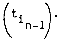
- Als Gesamtwert tg (= Summe zweier aufeinanderfolgender Teilwerte = gesamte Einspritzzeit je Zylinder und Arbeitsspiel) ergibt sich somit

- Theoretisch entspricht dann die eingespritzte Kraftstoffmenge in den Zylinder, der am nächsten zündet, derjenigen Kraftstoffmenge, die auch bei einer sequentiellen Einspritzung berechnet und ausgegeben würde. Aufgrund von dann auftretenden Regelschwingungen wird die Korrektur nicht zu 100 % durchgeführt, sondern die Differenz zwischen dem Rechenwert und dem letzten Teilwert mit einem Korrekturfaktor K < 1 bewertet. Ein sowohl für die Vermeidung der Regelschwingung als auch für eine in der Praxis ausreichende Korrektur der Gruppeneinspritzung hat sich ein Korrekturfaktor von 0,8 bewährt. Gemäß dem Ausführungsbeispiel würden mit diesem angegebenen Korrekturverfahren zum Zeitpunkt 0° KW ebenfalls 1 ms lang Kraftstoff eingespritzt, bei 360° KW beträgt die Einspritzzeit 2+ (2-1) x 0,8= 2,8 ms und bei 720° KW 6+ (6-2,8)x0,8 = 8,56 ms (gewählter Korrekturfaktor 0,8). Während des betrachteten Einspritzbereiches wird der Brennkraftmaschine Kraftstoff zugeführt, dem eine Einspritzzeit von insgesamt 11,36 ms anstelle der theoretisch benötigten 12 ms entspricht.
- Bezeichnet man die theoretisch nötigte Einspritzzeit (12 ms) als Sollwert und die tatsächliche Einspritzzeit als Istwert (8 ms bzw. 11,36 ms), so sinkt der relative Fehler im Falle der unkorrigierten Gruppeneinspritzung von (12-8)/12=33 % auf einen Wert (12-11,36)/12=5,3 % bei korrigierter Gruppeneinspritzzeit.
Durch das erfindungsgemäße Verfahren läßt sich unter Beibehaltung des gegenüber der sequentiellen Einspritzung aufwandarmeren Gruppeneinspritzverfahren eine Korrektur der Gruppeneinspritzzeit erreichen, so daß der Aktualisierungsunterschied zur sequentiellen Einspritzung minimiert ist.
Claims (2)
- Verfahren zum Steuern einer Brennkraftmaschine während dynamischen Übergangszuständen mit mindesten zwei Gruppen von Zylindern, wobei- in die Ansaugrohre jeder Gruppe zweimal je Arbeitsspiel gleichzeitig Kraftstoff eingespritzt wird, dessen Menge durch die Teilwerte der beiden Einspritzzeiten bestimmt ist (Gruppeneinspritzung), und- jeder Teilwertdadurch gekennzeichnet, daß jeder Teilwert


 - aus dem Rechenwert
 - aus der mit einem Korrekturfaktor (K) bewerteten Differenz zwischen dem Rechenwert

- Verfahren nach Anspruch 1, dadurch gekennzeichnet, daß der Korrekturfaktor (K) < 1 ist.
Priority Applications (2)
| Application Number | Priority Date | Filing Date | Title |
|---|---|---|---|
| DE91116460T DE59101113D1 (de) | 1991-09-26 | 1991-09-26 | Verfahren zum Steuern einer Brennkraftmaschine während dynamischer Übergangszustände. |
| EP19910116460 EP0533979B1 (de) | 1991-09-26 | 1991-09-26 | Verfahren zum Steuern einer Brennkraftmaschine während dynamischer Übergangszustände |
Applications Claiming Priority (1)
| Application Number | Priority Date | Filing Date | Title |
|---|---|---|---|
| EP19910116460 EP0533979B1 (de) | 1991-09-26 | 1991-09-26 | Verfahren zum Steuern einer Brennkraftmaschine während dynamischer Übergangszustände |
Publications (2)
| Publication Number | Publication Date |
|---|---|
| EP0533979A1 true EP0533979A1 (de) | 1993-03-31 |
| EP0533979B1 EP0533979B1 (de) | 1994-03-02 |
Family
ID=8207201
Family Applications (1)
| Application Number | Title | Priority Date | Filing Date |
|---|---|---|---|
| EP19910116460 Expired - Lifetime EP0533979B1 (de) | 1991-09-26 | 1991-09-26 | Verfahren zum Steuern einer Brennkraftmaschine während dynamischer Übergangszustände |
Country Status (2)
| Country | Link |
|---|---|
| EP (1) | EP0533979B1 (de) |
| DE (1) | DE59101113D1 (de) |
Citations (3)
| Publication number | Priority date | Publication date | Assignee | Title |
|---|---|---|---|---|
| US4401087A (en) * | 1980-04-03 | 1983-08-30 | Nissan Motor Company, Ltd. | Method and apparatus for engine control |
| EP0199181A2 (de) * | 1985-04-08 | 1986-10-29 | Toyota Jidosha Kabushiki Kaisha | Kraftstoffeinspritzungssystem für Innenbrennkraftmaschine |
| US4961411A (en) * | 1987-05-18 | 1990-10-09 | Nissan Motor Company, Limited | Fuel control apparatus |
-
1991
- 1991-09-26 DE DE91116460T patent/DE59101113D1/de not_active Expired - Fee Related
- 1991-09-26 EP EP19910116460 patent/EP0533979B1/de not_active Expired - Lifetime
Patent Citations (3)
| Publication number | Priority date | Publication date | Assignee | Title |
|---|---|---|---|---|
| US4401087A (en) * | 1980-04-03 | 1983-08-30 | Nissan Motor Company, Ltd. | Method and apparatus for engine control |
| EP0199181A2 (de) * | 1985-04-08 | 1986-10-29 | Toyota Jidosha Kabushiki Kaisha | Kraftstoffeinspritzungssystem für Innenbrennkraftmaschine |
| US4961411A (en) * | 1987-05-18 | 1990-10-09 | Nissan Motor Company, Limited | Fuel control apparatus |
Non-Patent Citations (1)
| Title |
|---|
| PATENT ABSTRACTS OF JAPAN vol. 009, no. 014 (M-352)22. Januar 1985 & JP-A-59 162 333 ( TOYOTA JIDOSHA K.K. ) 13. September 1984 * |
Also Published As
| Publication number | Publication date |
|---|---|
| DE59101113D1 (de) | 1994-04-07 |
| EP0533979B1 (de) | 1994-03-02 |
Similar Documents
| Publication | Publication Date | Title |
|---|---|---|
| DE19945618B4 (de) | Verfahren und Vorrichtung zur Steuerung eines Kraftstoffzumeßsystems einer Brennkraftmaschine | |
| DE102008054690B4 (de) | Verfahren und Vorrichtung zur Kalibrierung von Teileinspritzungen in einer Brennkraftmaschine, insbesondere eines Kraftfahrzeugs | |
| DE102008043165B4 (de) | Verfahren und Vorrichtung zur Kalibrierung der Voreinspritzmenge einer Brennkraftmaschine, insbesondere eines Kraftfahrzeugs | |
| DE3341200C2 (de) | Verfahren und Anordnung zum Regeln des Luft/Brennstoff-Verhältnisses bei einem Verbrennungsmotor | |
| DE3108601C2 (de) | Verfahren zur Steuerung der Kraftstoffeinspritzung bei einer Brennkraftmaschine | |
| DE19828710A1 (de) | Verfahren und Vorrichtung zum Steuern der Kraftstoffzuführung während Übergangszuständen eines Verbrennungsmotors | |
| DE2929516C2 (de) | Elektrisch gesteuerte Kraftstoffeinspritzeinrichtung für eine Mehrzylinder-Brennkraftmaschine | |
| DE3011595A1 (de) | Korrektureinrichtung fuer ein kraftstoffmesssystem bei einer brennkraftmaschine | |
| DE3423144A1 (de) | Verfahren zum steuern der kraftstoffzufuhr zu einer brennkraftmaschine bei beschleunigung | |
| DE69127030T2 (de) | Methode und Vorrichtung zur Kraftstoffeinspritzungssteuerung für eine Brennkraftmaschine | |
| DE60203223T2 (de) | Kraftstoffeinspritzungssteuerung für Brennkraftmaschine | |
| DE3241761C2 (de) | ||
| DE3940385A1 (de) | Kraftstoffeinspritzregeleinrichtung fuer eine brennkraftmaschine | |
| DE3242795A1 (de) | Vorrichtung zur korrektur des luft/kraftstoffverhaeltnisses fuer eine verbrennungsmaschine in abhaengigkeit von der ansaugtemperatur | |
| DE3033526A1 (de) | Elektronisches steuerverfahren fuer brennkraftmaschinen | |
| DE69011980T2 (de) | Kraftstoffsteuerungssystem für Verbrennungsmotoren. | |
| DE3226026A1 (de) | Verfahren und vorrichtung zur elektronischen regelung einer brennkraftmaschine | |
| DE19705463A1 (de) | Verfahren und Vorrichtung zur Steuerung einer Brennkraftmaschine | |
| DE3526895A1 (de) | Anordnung zum regeln des luft-brennstoff-verhaeltnisses eines kraftfahrzeugmotors | |
| EP1090221B1 (de) | Verfahren zum betreiben einer brennkraftmaschine insbesondere eines kraftfahrzeugs | |
| DE19581053B4 (de) | Verfahren und Vorrichtung für eine adaptive Kraftstoffzumessung bei Zweitaktmotoren | |
| DE3922116A1 (de) | Verfahren und vorrichtung zur kraftstoffeinspritzung bei einer brennkraftmaschine | |
| DE3418387C2 (de) | ||
| DE3923478C2 (de) | Sequentielle Kraftstoffeinspritzung mit Vorabspritzer | |
| DE19612453A1 (de) | Verfahren zum Bestimmen der in das Saugrohr oder in den Zylinder einer Brennkraftmaschine einzubringenden Kraftstoffmasse |
Legal Events
| Date | Code | Title | Description |
|---|---|---|---|
| PUAI | Public reference made under article 153(3) epc to a published international application that has entered the european phase |
Free format text: ORIGINAL CODE: 0009012 |
|
| AK | Designated contracting states |
Kind code of ref document: A1 Designated state(s): DE FR GB IT |
|
| 17P | Request for examination filed |
Effective date: 19930422 |
|
| 17Q | First examination report despatched |
Effective date: 19930625 |
|
| GRAA | (expected) grant |
Free format text: ORIGINAL CODE: 0009210 |
|
| AK | Designated contracting states |
Kind code of ref document: B1 Designated state(s): DE FR GB IT |
|
| REF | Corresponds to: |
Ref document number: 59101113 Country of ref document: DE Date of ref document: 19940407 |
|
| ITF | It: translation for a ep patent filed | ||
| GBT | Gb: translation of ep patent filed (gb section 77(6)(a)/1977) |
Effective date: 19940509 |
|
| ET | Fr: translation filed | ||
| ET1 | Fr: translation filed ** revision of the translation of the patent or the claims | ||
| PLBE | No opposition filed within time limit |
Free format text: ORIGINAL CODE: 0009261 |
|
| STAA | Information on the status of an ep patent application or granted ep patent |
Free format text: STATUS: NO OPPOSITION FILED WITHIN TIME LIMIT |
|
| 26N | No opposition filed | ||
| PGFP | Annual fee paid to national office [announced via postgrant information from national office to epo] |
Ref country code: GB Payment date: 19970826 Year of fee payment: 7 |
|
| PGFP | Annual fee paid to national office [announced via postgrant information from national office to epo] |
Ref country code: FR Payment date: 19970924 Year of fee payment: 7 |
|
| PGFP | Annual fee paid to national office [announced via postgrant information from national office to epo] |
Ref country code: DE Payment date: 19971120 Year of fee payment: 7 |
|
| PG25 | Lapsed in a contracting state [announced via postgrant information from national office to epo] |
Ref country code: GB Free format text: LAPSE BECAUSE OF NON-PAYMENT OF DUE FEES Effective date: 19980926 |
|
| GBPC | Gb: european patent ceased through non-payment of renewal fee |
Effective date: 19980926 |
|
| PG25 | Lapsed in a contracting state [announced via postgrant information from national office to epo] |
Ref country code: FR Free format text: LAPSE BECAUSE OF NON-PAYMENT OF DUE FEES Effective date: 19990531 |
|
| PG25 | Lapsed in a contracting state [announced via postgrant information from national office to epo] |
Ref country code: DE Free format text: LAPSE BECAUSE OF NON-PAYMENT OF DUE FEES Effective date: 19990701 |
|
| REG | Reference to a national code |
Ref country code: FR Ref legal event code: ST |
|
| PG25 | Lapsed in a contracting state [announced via postgrant information from national office to epo] |
Ref country code: IT Free format text: LAPSE BECAUSE OF NON-PAYMENT OF DUE FEES;WARNING: LAPSES OF ITALIAN PATENTS WITH EFFECTIVE DATE BEFORE 2007 MAY HAVE OCCURRED AT ANY TIME BEFORE 2007. THE CORRECT EFFECTIVE DATE MAY BE DIFFERENT FROM THE ONE RECORDED. Effective date: 20050926 |